

Page 1
Instructions for use
3135 015 1210_
Page 2
Once your PHILIPS purchase is registered, you're eligible to receive all the privileges of owning a
PHILIPS product. So complete and return the Warranty Registration Card enclosed with your
purchase at once. And take advantage of these important benefits.
le
event of
owner of your model
Congratulations on your purchase,
PHILIPS
and welcome to the "family!"
Dear PHILIPS product owner:
Thank you for your confidence in PHILIPS. You've selected one of the best-built, best-backed
products available today. And we'll do everything in our power to keep you happy with your purchase
for many years to come.
As a member of the PHILIPS "family," you're entitled to protection by one of the most comprehensive
warranties and outstanding service networks in the industry.
What's more, your purchase guarantees you'll receive all the information and special offers for which
you qualify, plus easy access to accessories from our convenient home shopping network.
And most importantly you can count on our uncompromising commitment to your total satisfaction.
All of this is our way of saying welcome-and thanks for investing in a PHILIPS product.
Sincerely,
Robert Minkhorst
President and Chief Executive Officer
P.S. Remember, to get the most from your PHILIPS
product, you must returnyour Warranty
Registration Card within 10 days. So please mail it
to us rightnow!
Know these
safetysymbols
,_ This "bolt of lightning" indicates uninsulated material within your unit which may cause an
electrical shock. For the safety of everyone in your household, please do not remove product
covering.
,_The "exclamation point" calls attention to features for which you should read the enclosed
literature closely to prevent operating and maintenance problems.
WARNING: TO PREVENT FIRE OR SHOCK HAZARD, DO NOT EXPOSE THIS EQUIPMENT
TO RAIN OR MOISTURE.
CAUTION: To prevent electric shock, match wide blade of plug to wide slot, and fully insert.
ATFENTION: Pour 6viter les chocs _lectdques, introduire la lame la plus large de la fiche dans la
borne correspondante de la prise et pousser jusqu'au fond.
Page 3
SAFETYINSTRUCTIONS- Readbeforeoperatingequipment
This product was designed and manufactured to meet strict quality and 11. Power-Cord Protection- Power supply cords should be routed so
safety standards. There are, however, some installation and operation that they are not likelyto be walked on or pinchedby items placed
precautions which you should beparticularly aware of. upon or against them, paying particular attention to cords and
1. Read Instructions- All the safety and operating instructions should
be read beforethe appliance is operated.
2. Retain Instructions - The safety and operating instructions should
be retained forfuture reference.
3. Heed Warnings - All warnings on the appliance and in the operating
instructions should beadheredto.
4. Follow Instructions - All operating and use instructions should be
followed.
5. Water and Moisture- The appliance should not be used near water
- for example, near a bathtub, washbowl, kitchen sink, laundry tub,
in a wet basement or near a swimming pool, etc.
6. Cartsand Stands- The appliance should be used only with a cart or
standthat is recommended by the manufacturer.
6A. _ An appliance and cart combination should be moved
with care. Quick stops, excessive force, and uneven
surfaces may cause the appliance and cart combinatior_
to overturn.
6B. Tilt/Stability - All televisions must comply with recommended
international global safety standards for tilt and stability properties
of itscabinet design.
Do not compromise these design standards byapplying exces-
sive pull force to the front, or top, of the cabinet which could
ultimately overturn the product.
Also, donot endangeryourself, or children, by placing elec-
tronic equipmentJtoyson the top of the cabinet. Such items
could unsuspectingly fall from the top of the set and cause
product damageand/or personal injury.
7. Wall or Ceiling Mounting- The appliance should be mounted to a
wall or ceiling only asrecommended by the manufacturer.
8. Ventilation - The appliance should be situated so that its location or
position does not interfere with its proper ventilation. For example,
the appliance should not besituated on a bed, sofa, rug, or similar
surface that may block the ventilation openings; or, placed in a
built-in installation, such as a bookcase or cabinet that may impede
the flow of air through the ventilation openings.
9. Heat - The appliance should be situated away from heat sources
such as radiators, heat registers, stoves, or other appliances
(including amplifiers) that produceheat.
10. Power Sources - The appliance should be connected to a power
supply only of the type described in the operating instructions or as
marked on the appliance.
plugs, convenience receptacles, and the point where they exit from
the appliance.
12. Cleaning - The appliance should be cleaned only as recommended
bythe manufacturer.
13. Power Lines - An outdoor antenna should be located away from
power lines.
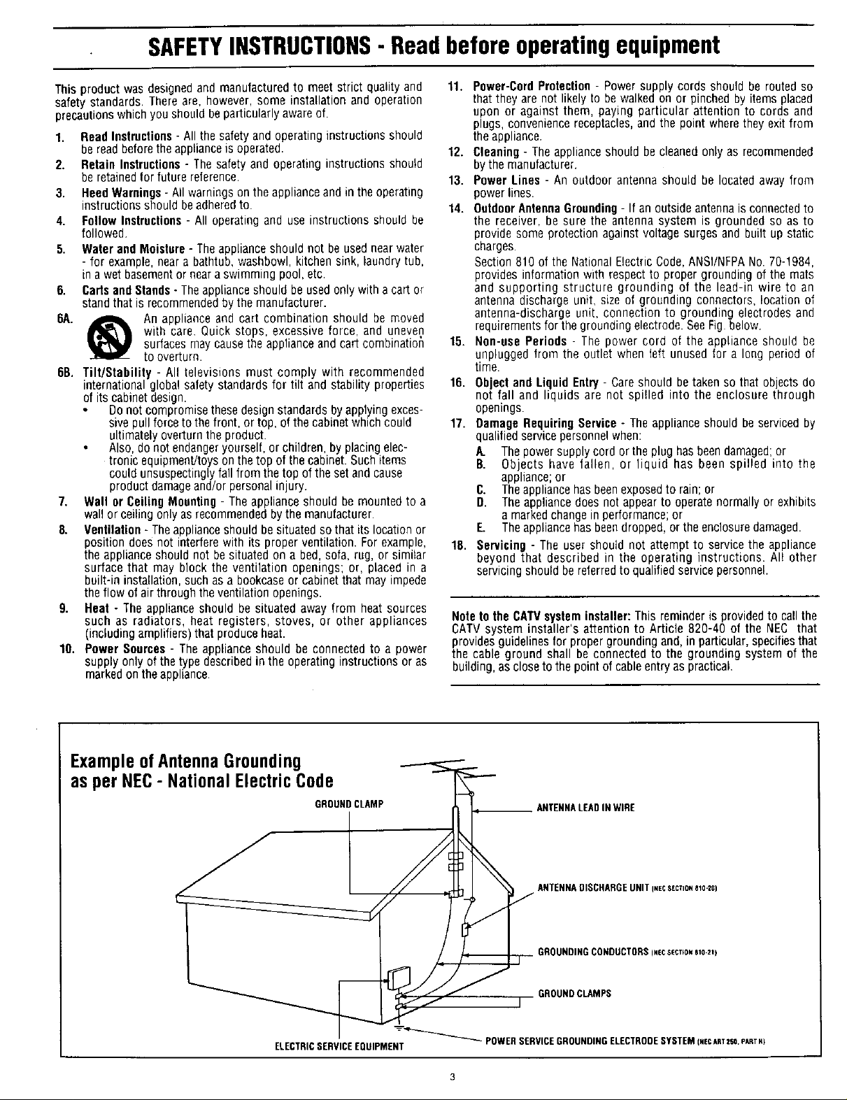
14. OutdoorAntennaGrounding- If an outside antenna is connected to
the receiver, be sure the antenna system is grounded so as to
provide some protection against voltage surges and built up static
charges.
Section 810 of the National Electric Code, ANSI/NFPANo. 70-1984,
provides information with respect to proper grounding of the mats
and supporting structure grounding of the lead-in wire to an
antenna discharge unit, size of grounding connectors, location of
antenna-discharge unit, connection to grounding electrodes and
requirements for thegrounding electrode. SeeFig below.
15. Non-use Periods - The power cord of the appliance should be
unplugged from the outlet when teft unused for a long period of
time.
16. Object and Liquid Entry - Careshould betaken so that objects do
not fall and liquids are not spilled into the enclosure through
openings.
17. Damage RequiringService - The appliance should be serviced by
qualified service personnel when:
A. The power supply cord or the plug has beendamaged; or
B. Objects have fallen, or liquid has been spilled into the
appliance;or
C. Theappliance hasbeenexposed to rain; or
D. The appliance does not appear to operatenormally or exhibits
a markedchange in performance; or
E. The appliance has beendropped, or the enclosure damaged.
18. Servicing - The user should not attempt to service the appliance
beyond that described in the operating instructions. Al! other
servicing should be referred to qualified service personnel.
Noteto the CATVsysteminstaller: This reminder is provided to call the
CATVsystem installer's attention to Article 820-40 of the NEC that
providesguidelinesfor propergrounding and, in particular,specifiesthat
the cable ground shall be connected to the grounding system of the
building, asclose to the point of cable entry as practical.
ExampleofAntennaGrounding
as per NEC- NationalElectricCode
GROUNDCLAMP
ELECTRICSERVICEEQUIPMENT
ANTENNALEADIN WIRE
ANTENNADISCHARGEUNITI.ECSeCTiONale-20)
GROUNDINGCONDUCTORSI,ecSECT[OI_810-21)
GROUND CLAMPS
I
_"_ POWERSERVICEGROUNDINGELECTRODESYSTEM I,EcART2SO.eART.)
Page 4
" _1 Gettiw, Started
_ Welcome/Product Registration ................... 2
Safety/Precautions ..................................................... 3
Table of Contents ....................................................... 4
Features, Model and Cabinet Information ........... .._..5
iii .ll i
[] NTSC Analog On-Screen Menu Features
FIRST TIME SETUP
+Automatic Programming of Ioca[ NTSC
Channels and other Control Features ................. 6
PICTURE MENU
+Adjusting Color, Brightness, Sharpness.
Tint, and Picture Controls ................................... 7
+Using the Clearvicw Control ............................... 8
+Adjusting the DPTV's Convergence Control ......9
ATSC Diaital On-Screen
Menu Features
DTV SETUP
+Automatic Programming of area Digital
(ovcr-tbe-air) Broadcast Channels ................... 29
PICTURE MENU
+Adjusting Color, Brightness, Sharpness,
Tint, and Picture Controls ................................. 30
+Adjusting DTV Convergence ............................ 31
SOUND MENU
+Surround Sound Speaker Connections .............. 32
+Selecting the DPTV Surround Mode Control,.,33
"¢'Dolby Digital Internal and External Speaker
System Use and Connections ...................... 33-34
+Adjusting Bass and Treble Sound Controls ....,.35
_ing the Auto Volume Control ....................... 35
FEATURES MENU
+Setting the Smart Picture Controls .............. 10-11
+Setting the DPTV tot Closed Captioning .......... 12
+Setting the DPTV for Cable/Antenna Signals,,. 13
+Adding Channels in Memory (Automatically) .14
+Adding Channels in Memory (Manually) ......... 15
+Setting the DPTV Clock .................................... 16
+Adjusting the Channel Display Control ............ 17
+Using the Channel Label Control ..................... 18
SOUND MENU
+Adjusting Bass, Treble. and Balance Sound
Controls ............................................................. 19
+Setting the DPTV for Stereo/SAP Programs ...20
+Using the Volume Display Control ................... 21
+Using the Automatic Volume Limiter Control .22
Pronto Remote NTSC Features
SPEAKERS MENU
"ffAdj_fi_ Speaker Menu Contr0i_ for
_ MONITOR On-Screen Features
+Connection of VGA/SVGA/and High Definition
(HD) Component Video auxiliary equipment .41
+Analog NTSC D_ Features .......................... 23
M General Information
Tips if Something Isn't Working ............... 43
Cleaning and Care .................................................... 43
Index ........................................................................ 44
Regulatory Notices .................................................. 44
G!pssarY of DPTV Terms ..;,:_............................. .::.45
Fa_t6_ Se_!_e L_ations...i : i-. .......... : )ii_A6 47
Copyright © 1998 Philips Consumer Elecmmics. All rights reserved.
4
Page 5
ATSC Certified - for full compliance with analog
NTSC and all 18 digital ATSC formats as specified by
the Federal Communications Commission (FCC).
High Definition Digital - with full 1920 x 1080
interlaced image resolution capability to achieve
superior image perforn3ance.
64" Widescreen Display - with a super-large 64"
Widescrecn 16:9 display lbrmat which provides lot a
true home theater or cinematic experience. If a 4:3
aspect ratio picture is the primary source, it will be
expanded to fill the screen.
120-Watt Amplifier - to provide up to 20 watts
amplification for each of the Left/Right front, Center,
Left/Right rear Surround, and Subwoofer channel
speakers.
First Time Set Up - for both NTSC and ATSC
channel programming to automatically preset the
DPTV for available area stations.
TV Guide Plus+ TM Programming - which downloads
NTSC channel program information including on-
screen program summaries and sorts by viewing
preference categories (sports, movies, etc.). Microchip
Storagecapacity and channel availability determine
volume of downloaded data.
Pronto Remote Control - universali learn remote
which controls virtually a!l IRdevices, learns new
commands as your system expands, and can be
customized according to _our _rsonal preferences.
Featuring a large LCD ba klit iouchscr_i the Pronto
gives you easy access to all key D_ features.
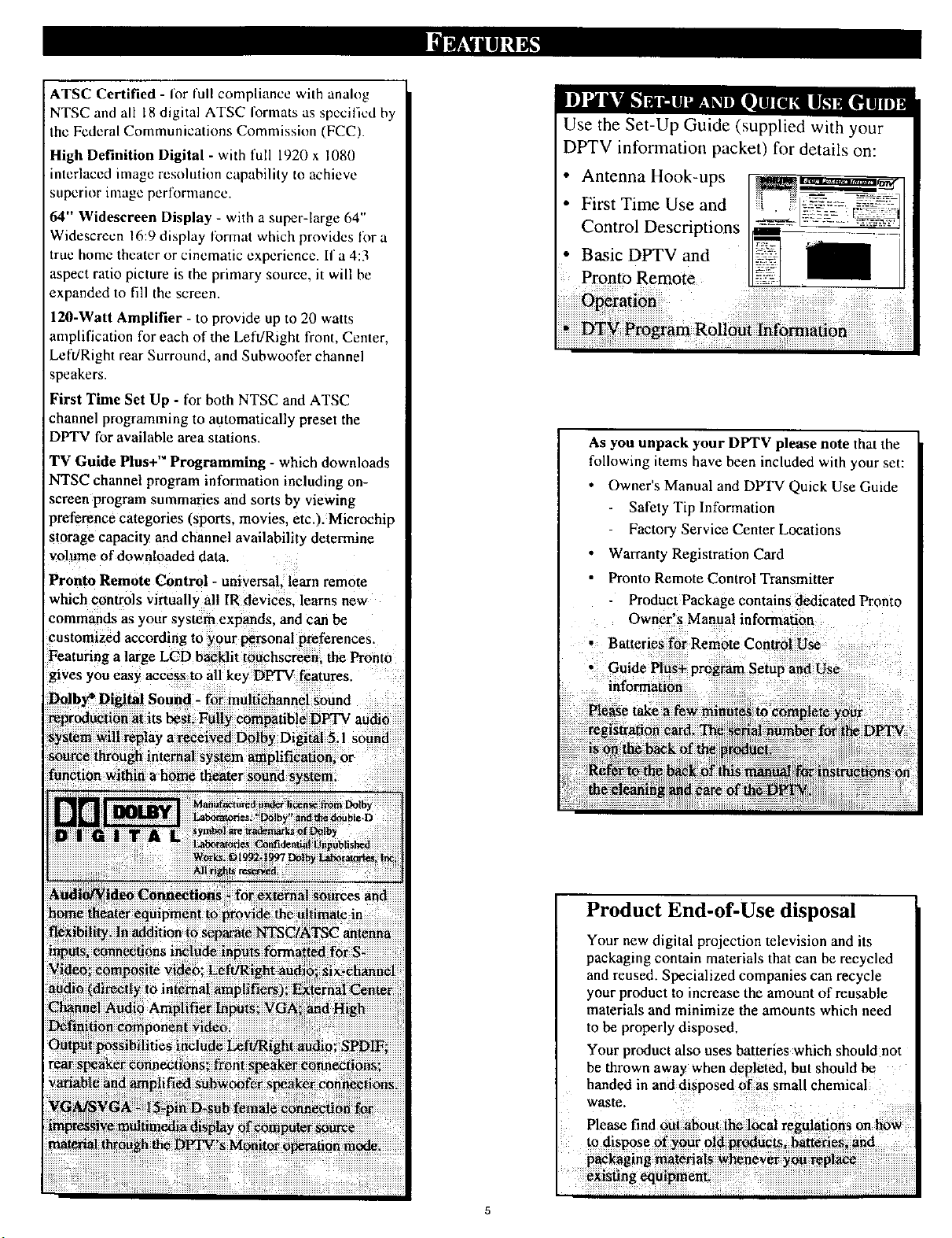
Use the Set-Up Guide (supplied with your
DPTV information packet) for details on:
• Antenna Hook-ups
• First Time Use and
Control Descriptions
• Basic DPTV and
Pronto Remote
As you unpack your DPTV please note that the
following items have been included with your set:
Owner's Manual and DPTV Quick Use Guide
Safety Tilz Information
Factory Service Center Locations
Warranty Registration Card
Pronto Remote Control Transmitter
Product Package contains dedicated Pronto
Owner's Manual information
Batteries for Remote Control Use
• Guide Plu_ program Setup and Use
information
Please take
Product End-of-Use disposal
Your new digital projection television and its
packaging contain materials that can be recycled
and reused. Specialized companies can recycle
your product to increase the amount of reusable
materials and minimize the amounts which need
to be properly disposed,
Your product also uses batteries which should not
be thrown away when depletedl but should be
handed in and disposed of as small chemical
Page 6
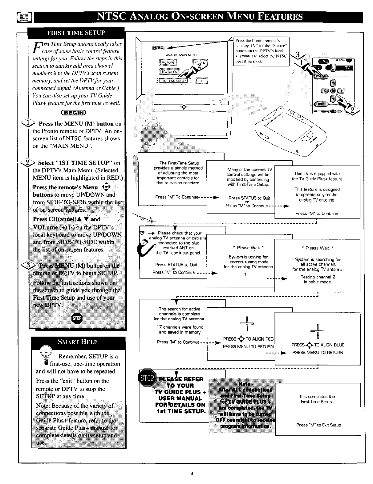
FcrSt Time Setup atttomatically takes
are of some basic control feature
settings for you. Follow the steps in this
section to quickly a&l area channel
tutmbers into the DPTV's scan system
mentory, and set the DPTV for your
connected signal (Antenna or Cable.)
You can also set-up your TV Guide
Plus+feature for the first time as well.
_ Press the MENU (M) button on
the Pronto remote or DPTV. An on-
screen list of NTSC features shows
on the "MAIN MENU".
!ii!iiiii!iiii!i!i! il¸¸¸ iiiiiii!iii!!iiiiiiiiiiiiiiiiiii!iiii:!iiii ii , ,,,,_...........
_ Select "IST TIME SETUP" on
the DPTV's Main Menu. "Selected
MENU item is highlighted in RED.)
Press the remote's Menu t_)
buttons to move uP[DOWN and
from SIDE-TO-SIDE within the list
of on*screen f_eatures.
Press CHCannel)& • and
VOLume (+) (-) on theDPTV's
loealkeyboard to move UP/DOWN
and from SIDE-TO-SIDE within
Remember, SETUP is a
first-use, one-time operation
and will not have to be repeated.
Press the "exit" button on the
remot e or DPTV to stop the
SETUp at any time _
The FirsbTime Setup
provides a simple method
of adjusting the most
important controls for
this television receiver
Press "M* TO Cenunue- - -
Please _c_'eckthat your
analog TV antenn_ or cable is
:_ _connected to the plug
marked ANT on
e TV rear input panel
Press STATUS toQuit
Press "M"toOontinue ....
or
The search foractive
channels iscomplete
forthe analog TV antenna.
17 channels were found
and saved in memory
Press "M" to Continue..
USER MANUAL
FORq)ETA!LS ON
I
Many of the current TV
control settings will be
modified by continuing
with First-Time Setup.
• - _ Press STATUS to Quit ana_o-,_TV antenna
Press "M" to Continue .....
or
This TV is equipped with
me TV Guide Plus+ feature
This feature is designed
to operate only on the
Press "M" to ConPnue
,J
I
I
• Please Wait *
System is testing for
cerfect tuning mode
for the analog TV antenna
• Please Want *
System is searching for
all active channels
for the analog _/antenna
Testing channel 2
in cable mode
J
]
+
÷
PRESS _-TO ALIGN RED
"'_ PRESS MENU TO RETURN
PRESS _- TO ALIGN BLUE
--_ PRESS MENU TO RETURN
I
This completes the
FirsbTime Setup
Press "M" to Exit Setup
Page 7
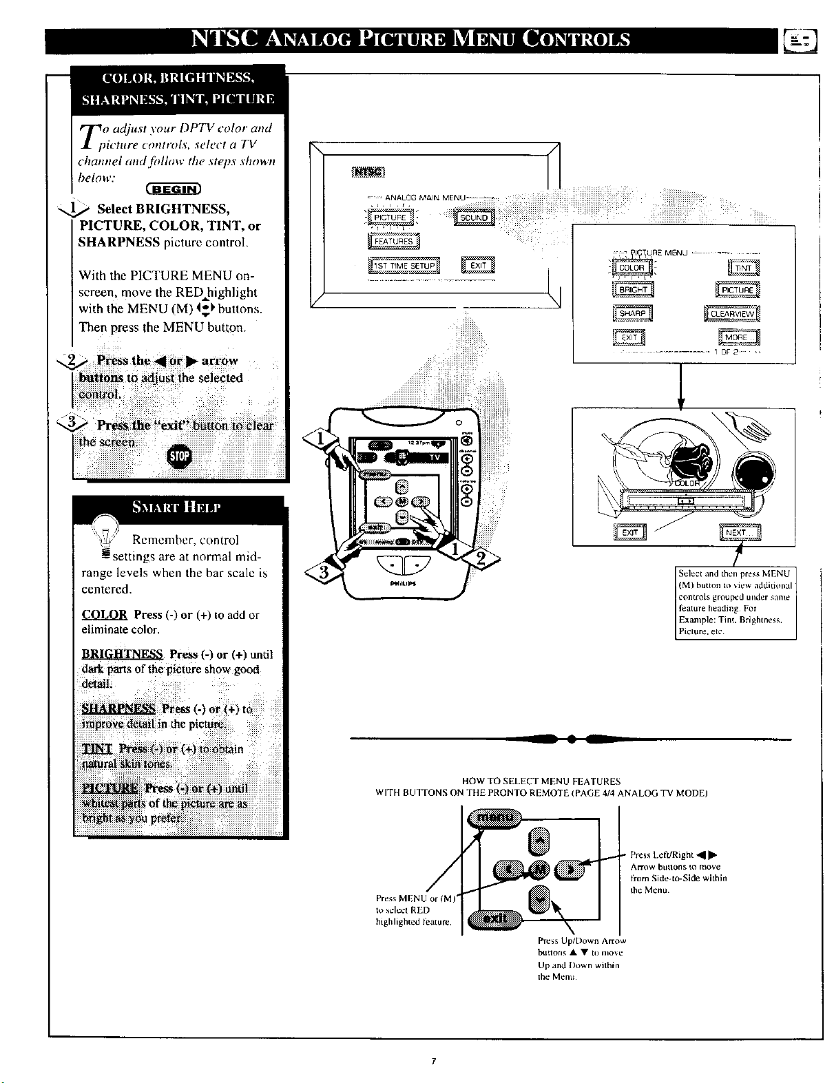
Zo adjust your DPTV color and
_icture controls, select a TV
channel and.fidlow the steps shown
below:
Select BRIGHTNESS•
PICTURE. COLOR. TINT. or
SHARPNESS picture control.
With the PICTURE MENU on-
screen, move the RED highlight
with the MENU (M) I_' buttons.
Then press the MENU button,
buttons to adjust the selected
control. "
f_3
:f • PI_TtURE MENU ......
............. 1 OF 2 :,
,!
Remember, control
settings are at normal mid-
range levels when the bar scale is
centered,
Press (-) or (+) to add or
eliminate color,
BRIGHTNESS Press (-) or (+) until
darkparts of the picture show good
(M) button Io _iew additkmal
controls grouped under same
feature heading For
Select and then press MENU
Example: Tim, Brightness,
Picture. etc
__ • L
WITH BUJTONS ON THE PRONTO REMOTE (PAGE 4/4 ANALOG TV MODE)
Press MENU or (M)*
to select RED
highlighted leature.
HOW TO SELECT MENU FEATURES
Press Up/l)own Arrow
btltlons • • to move
Up and Down wilhin
lhe Menu
• Press Left/Right 41[1_
AN-ow btlttons to move
from Side4o-Side within
the Menu
Page 8
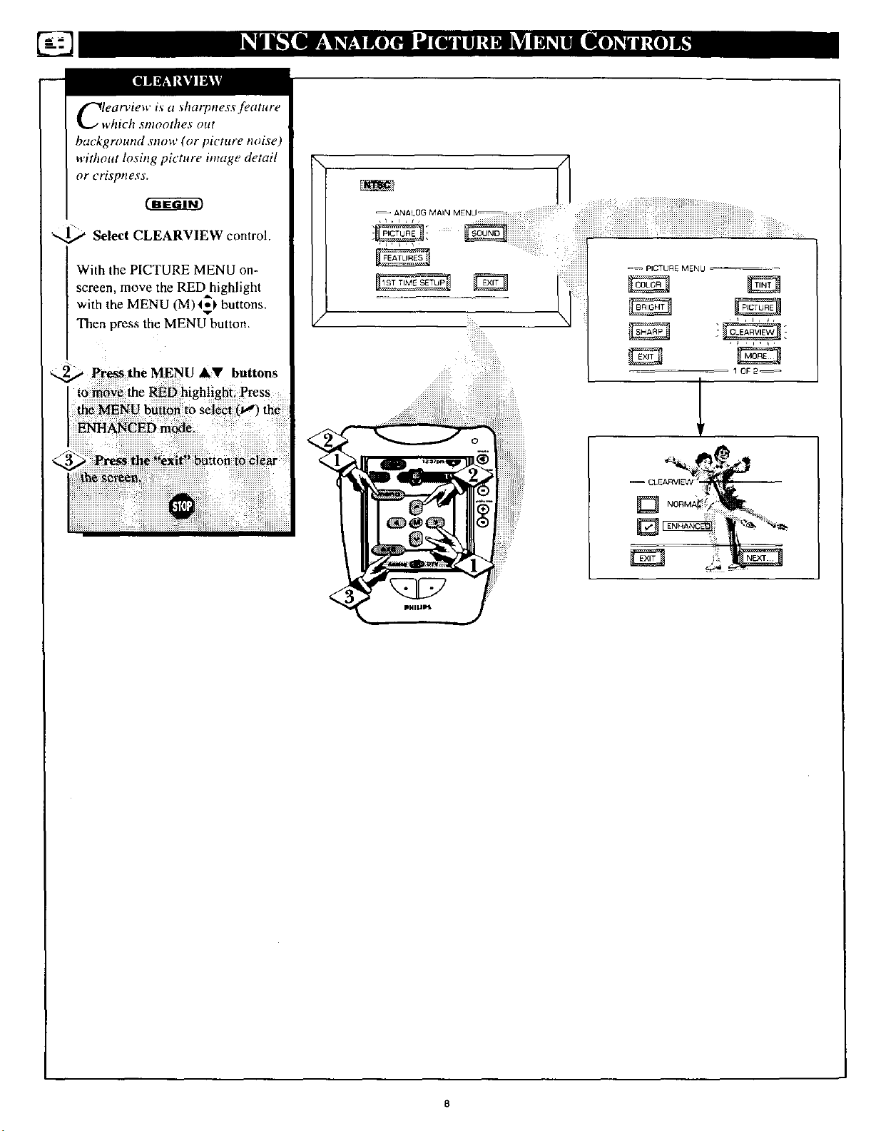
Clearview is a sharpness feature
which smoothes out
background stlow (or picture mffse)
without losittg picture image detail
or crisptless.
cg -ar
_ Select CLEARVIEW control.
With the PICTURE MENU on-
screen, move the RED highlight
with the MENU (M)4_!, buttons.
Then press the MENU button.
-- ANALOG MAIN MENU
Page 9
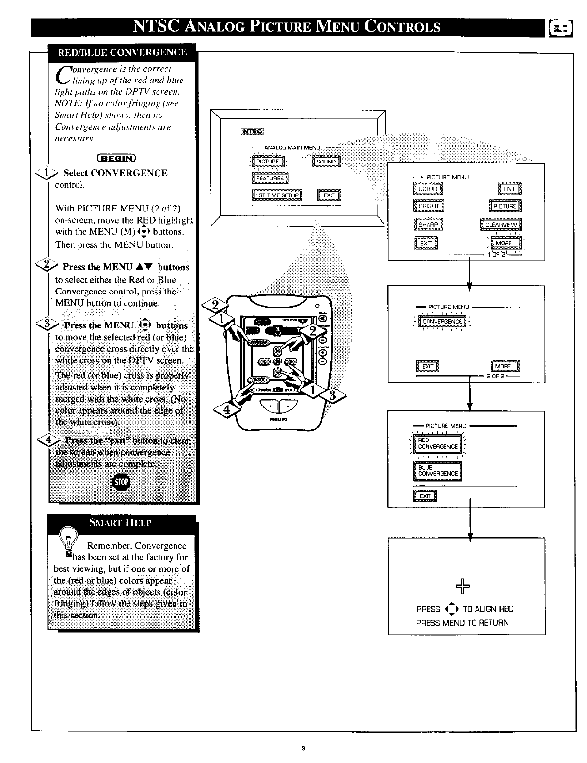
nvergence is the correct
ning up of the red and blue
light paths on the DPTV screen.
NOTE: I['no color fringing (see
Sntart Help) shows, then no
Convergence adjustments are
ilecessar%,.
Select CONVERGENCE
control.
With PICTURE MENU (2 of 2)
on-screen, move the RInD highlight
with the MENU (M)4_ buttons.
Then press the MENU button.
_' Press the MENU &_l' buttons
to select either the Red or Blue
Convergence control, press the
MENU button to continue.
_..._ Pre_s the MENU 4_1, buttons
to move the selected red 'or bluet
convergence cross directly over the
white cross on the DtrI'V screen.
The red (or blue'J cross is properly
adjusted when it is completely
, _ PICTURE MENU
iii_i
_ili_!iiiiiiiiii!ii!!iii_ilililililililililili_
1 _0#_2q_
!i!iii!i!i!iii!i!i!i!i!i!i!i!i!i!i!i!i!i!i!i!i!i!i!i!i!i!i!i!,
-- PICTURE MENU
• ' , , ,
- 20F2_
-- PICTURE MENU
...... ,
Remember, Convergence
set at the factory for
best viewing, but if one or more of
the (red or b!ue) colors appear
\
+
PRESS '4:IP TO ALIGN RED
PRESS MENU TO RETURN
Page 10
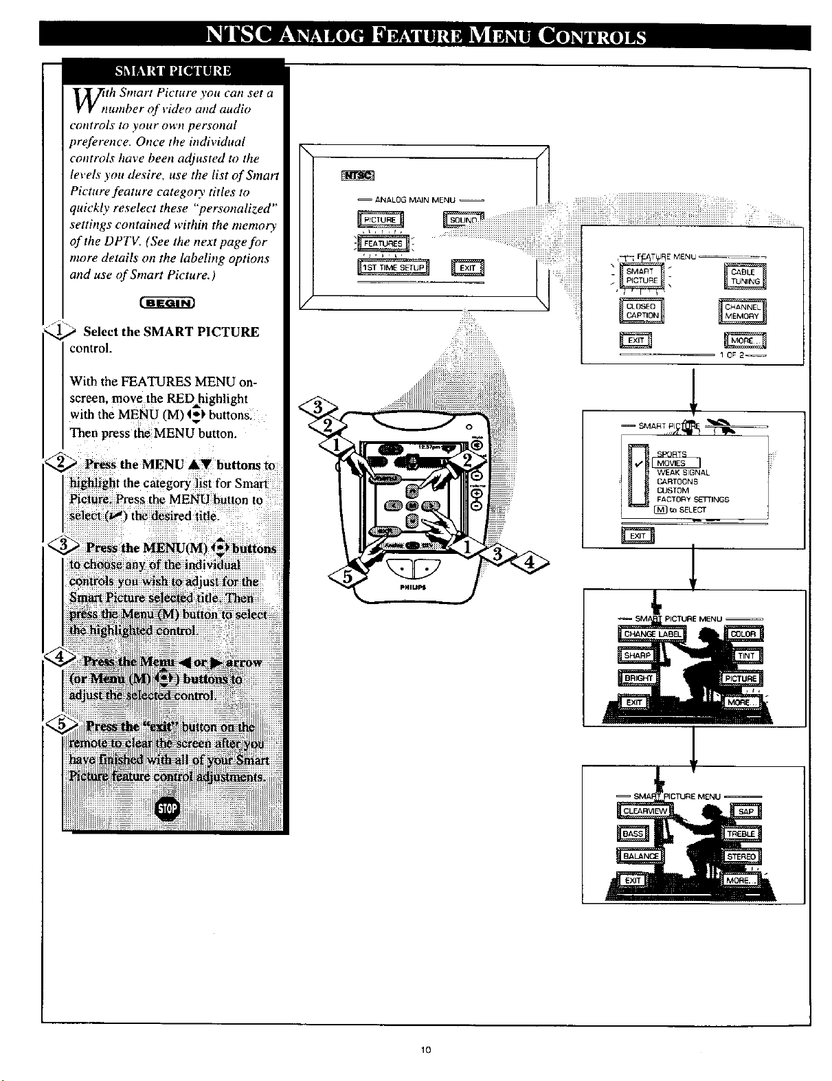
_tth Smart Picture you can set a
zumber of video and audio
controls to your owtt personal
preference. Once the individual
controls have been adjusted m the
levels you desire, use the list of Smart
Picture feature category titles to
quickly reselect these "'personalized"
setthzgs contained within the memo_
of the DPTV. (See the next page for
more details on the labeling options
and use of Smart Picture.)
Select the SMART PICTURE
control.
With the FEATURES MENU on-
screen, move the RED highlight
with the MENU (M) t_) buttons.
Then press the MENU button.
Picture. Press the MENU button to
select (w') the desired title.
i highlight the category I st for Smart
CARTOONS AL
U USTOMFACTORY SETTINGS
[_ ta SELECT
El
t,
PICTURE MENU --
10
Page 11
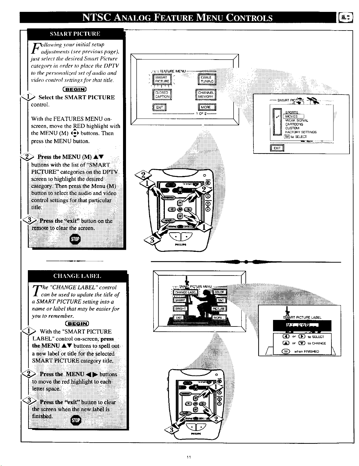
FallOwing your initial setup
djustments (see previous page),
just select the desired Sntart Picture
categoo' in order to place the DPTV
to the personalized set of audio and
video control settings for that title.
c_w_cm
Select the SMART PICTURE
control.
With the FEATURES MENU on-
screen, move the RED highlight with
the MENU (M) _' buttons. Then
press the MENU button.
_"@ Press the MENU (M) AV .....
bUtt6ns with the list 6f _!SMART
PICTURE" categories 6fi t_ D_
screen to highlight the d_si_d
Menu
_i_ to s_ieci _he audi6 and _id_
iiiiiiiiiiiiiiiiiiiiiii:_i_i_iiiiiiiiiiiiiiiiiiiiiiiiiiiiiii_i_!__!i_iii_i_iiii_!i_ii!_ _iiiiiiiiiiiiiiiiiiiiiiiiiiiiiiiiiii_i_i_ii!_iiiiiiiiiiiiiiii
!! !i ! ! !!!!! iii i!i!iiiiiiiiiiii!iiiiiiiiiiiiiiiiiiiiiii
_i_iiiiiiiiiiiiiii_i_ii_i_iiiiiiiiiiiiiiiiiiiiiiiiiiiiiiiiiiiiiiiiiiiiiiiiiiiiiiiiiiiii
Tehe "CHANGE LABEL" control
an be used to update the title of
a SMART PICTURE setting into a
name or label that may be easier for
you to remember.
With the "SMART PICTURE
LABEL" control on.screen; press
the MENU AV buttons tOspell out
a new label 0r title for the selected
11
Page 12
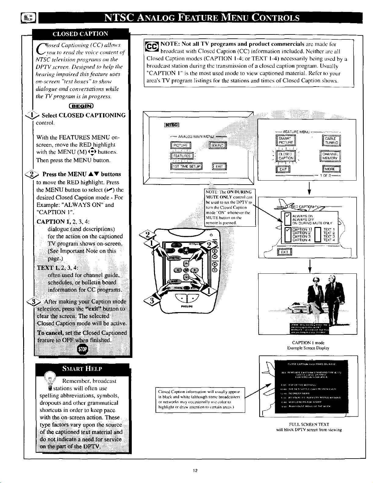
Closed Captioning (CC) allows
\'ou to re(td tilt, voi¢'e cotttent of
NTSC televisimt programs on the
DPTV screen. Designed to help the
hearing impaired this feature uses
on-screetl "text boxes" to show
dialogue and conversations while
the TV program is in progress.
_ Select CLOSED CAPTIONING
control.
With the FEATURES MENU on-
screen, move the RED highlight
with the MENU (M) t=_' buttons.
Then press the MENU button.
/_/" \
<_a Press the MENU &V buttons
to move the RED highlight. Press
the MENU button to select (tl) the
desired Closed Caption mode - For
Example: "ALWAYS ON" and
"CAPTION l".
CAPTION 1, 2.3.4:
dialogue rand descnptionsl
for the action on the captioned
TV program shows on-screen.
(See Important Note on this
pagc.)
_ NOTE: Not all TV programs and product commercials arc made for
broadcast v,.ith Closed Caption (CC) inff_rmation included. Neither are all
Closed Caption modes (CAPTION I-4; or TEXT I-4) necessarily being used by a
broadcast station during the transmission of a closed caption program. Usually
"CAPTION I" is the most used mode to view captioned material. Refer Io your
area's TV program listings for the stations and times of Closed Caption shows.
I
MUTE ONLY control can
be used to set Ihe DPqV to
turn the Closed Caption
mode ' ON' wbene_er the
NOTE: The ON DURING
MUTE button on the
remora is pressed.
ann¢l gai_
teti
!xitii but
Remember, broadcast
stations will often use
spelling abbreviations, symbols,
dropouts and other grammatical
shortcuts in order to keep pace
with the on-screen action. These
CAPTIONIm_e
ExampleScreenDisplay
Closed Caption inlomlation will usually appear
in black and white (ahbough some broadcasters
or n_tworks may oc_:asioI_ally use color to
highlight or draw attenlion to certain areas )
FULL SCREEN TEXT
will block DVI'V screen from viewing
12
Page 13
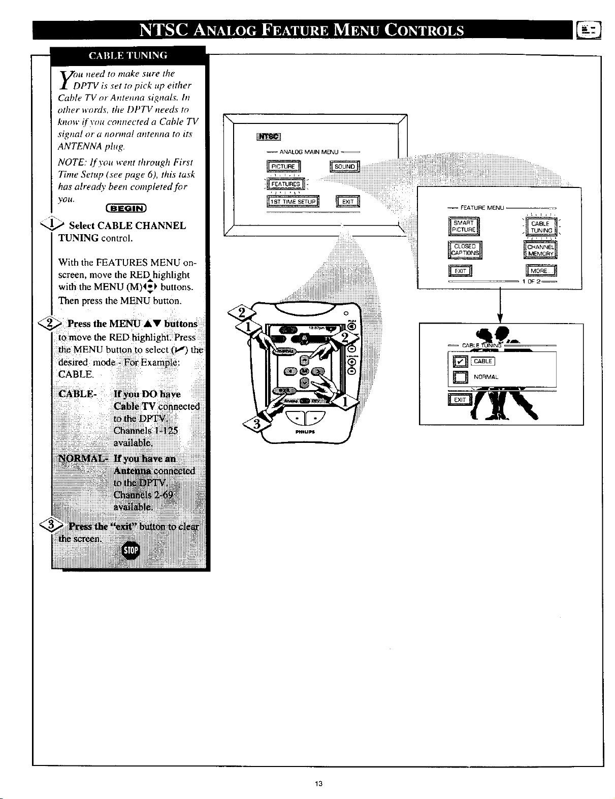
yoDu need to make sure the
PTV is set to pick up either
Cable TV or Antenna signals, hi
other words, the DPTV needs to
know if you connected a Cable TV
sigtta[ or (l tlorma[ atltetltta to its
ANTENNA plug.
NOTE: If you went through First
Time Setup (see page 6), this task
has already been completed for
yOU.
]_ Select CABLE CHANNEL
TUNING control.
With the FEATURES MENU on-
screen, move the REDhighlight
with the MENU (M)4_ buttons.
Then press the MENU button.
_--._ Press the MENU AV buttons
[o move the RED highlight. Press
the MENU button to select 01) the
desired mode - For Example:
CABLE,
-- _EATURE MENU ,
1 0_2--
_cAoL , 9--
availal_le.
feted
13
Page 14
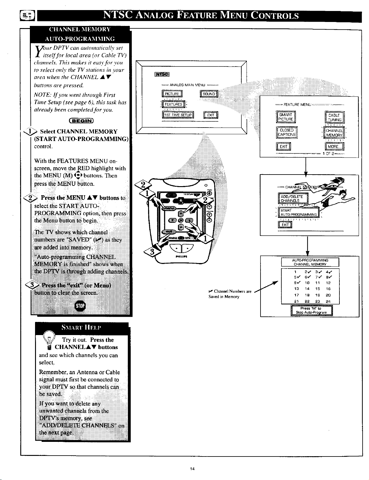
Eour DPTV can automatically set
tself for local area (or Cable TV)
channels. This makes it easy for you
to select onl\' the TV stations in your
area when the CHANNEL • •
buttons are pressed.
NOTE: lf you went through First
Time Setup (see page 6), this task has
already been completed for you.
_ Select CHANNEL MEMORY
(START
control.
With the FEATURES MENU on-
screen, move the RED highlight with
the MENU (M) t_l, buttons. Then
press the MENU button.
2_ Press the MENU A!ll' buttons to
select the START AUTO-
PROGRAMMING option, then press
the Menu button to begin.
--ANALOG MAIN MENU _==
--= FEATURE MENLJ
The TV shows which channel
numbers are "SAVED" it,,s) as they
Try it out. Press the
CHANNELA• buttons
and see which channels you can
select.
Remember, an Antenna or Cable
sigma! m_st first be connected to
you_ D_ so that channeiS cab
I_' Channel Numbers are f
Saved in Memory
L AUTO.PROGRAMMING
CHANNEL MEMORY
1 2.,," 3./ 4v"
5"d" 6_ 7,v" B_"
J 9 *z" 10 11 12
13 14 15 16
17 1B 1£ 2Q
21 22 23 24
14
Page 15
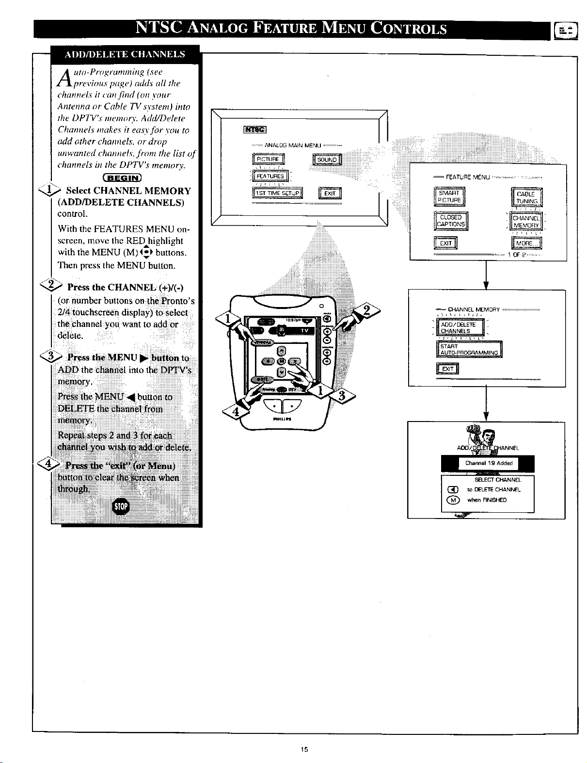
Auto-Programming (see
previous page) adds all the
channels it canjind (on your
Antenna or Cable TV system) htto
the DPTV's memory. Add/Delete
Channels makes it eao'for you to
add other channels, or drop
unwanted channels, ftvm the list of
channels tit the DPTV's memory.
_ Select CHANNEL MEMORY
(ADD/DELETE CHANNELS)
control.
With the FEATURES MENU on-
screen, move the RED highlight
with the MENU (M)45_ buttons.
Then press the MENU button.
_-_ Press the CHANNEL (+)/(-)
(or number buttons on the Pronto's
2/4 touchsereen display) to select
the channel you want to add or
delete.
CHANNEL MEMORY
3_ Press the MENU • button to
) the channel into the DPTV's
button to
to DELETECHANNEL
when FINISHED
(_} SELECT CH&NNEL
15
Page 16

F_ur DPTV comes with an on-
creen clock. During normal
operation the clock appeat=_ on the
screen with every challnel change
(and when the STATUS button is
pre._sed).
_ Select SET CLOCK control.
With FEATURES MENU (2 of 2)
on screen, move the RED highlight
with the MENU (M) 4,'_ buttons.
Then press the MENU button.
,._ Press the remote's number
buttons (on the Pronto's 2/4
touchscreen display) to set the time
clock.
/3 _
Press the "exit" button to set
the clock in operation and clear the
screen.
\
_= = FEATUR E MENU ............
.=_ AN_.LOGMA,_ME.u_iiiiiiiiiiiiiiii
/
iiiiL
_i!!!_i__ i_i:!_i
i__i__i!__/_
j2 jiiiiiiiiii i!iiiiiiiiiiiiiii iii i!i!!!i iii
20F2 ....
Remember, be sure to
iWpress "0" first and then the
hour number for single digit
entries.
The rem0te's MENU (M) 1_)
buttons _n also b_ used to set the
l
SET CL K
PLEASE USE AorV
16
Page 17

[III l!@l IIII] [IJ[_']i1IF.If
_/_cth the Channel Display
otttrol you can change the
size and location of the on-screen
channel attd clock inforntation.
1',_ Select CHANNEL DISPLAY
control.
With FEATURES MENU (2 of 2)
on-screen, move the RED _,
highlight with the MENU (M)4_)
buttons. Then press the MENU
I button•
Press the MENU AV and
MENU IM) buttons to highlight
the LARGE or
_ FF_TUR E MENU ........
=-_ANALOGMAINMEI_JU _iiiiiiiiiiiiiiiiiiiiiiiiiiiiiiiiiiiiiiiiiiiiiiiiiiiiiiiiiiiiiiiiiiiiiiiii
lr
-- FEATURE MENU
20F2--
--CHaNNELD,SPS
............................... [] SMALL-CH_4
i!iiiiiiii[iii!iiii!iiiiiiiiiiiii?i........m ' ........
:_iii:_iN_i_i:!i!iiiii:ili:_iiiiiiiiiiiiiiiiiiiiiiiiiiiiiiiiiiiiiiiiiiiiiiiiiiiiiiiiiiiiiiiiiii
_i!iiii_i?,,;i)i:iiiiiiiiiiiiiiiiiiiiiiiiiiiiiiii_...... ................
2
2
m
10:O6
CHANNELDISPLAYOPTIONS
17
Page 18

Do you ever have trouble
rentembering on which
channel a particular station or
network is located? The Channel
Labels Control is a quick way to
view attd select channels from a
list of Labeled channels.
A Label is a four letter callout you
can set to appear with the on-
screen chatmel number. Example
Label: WXYZ - for a TV station's
call letters.
To create station labels using the
Channel Labels Controh
_._ Select CHANNEL LABELS
control.
With the FEATURE MENU (2 of
2) on-screen, move the RED
highlight using the MENU (M) _1_t.
buttons. Then press the MENU
(M) button.
2aF2--
Jr Own
Choose From List
V
GUIDE LABEL
ct DE) to SIELECT
(_ or {_) to CHANGE
)when FINISHED
MANUAL- To create your
own Channel Label:
Press the Channel &.V or
Number buttons to select
desired station.
A red highlight shows the
active letter space for the
channel label.
Press the MENU • •
buttons to pick any of the
letters or symbols that are
_iven for your use.
Press the MENU • •
buttons to move the red
highlight to the other letter
spaces and repeat.
Press the STATUS button
to clear the screen when
finished.
(_ (_ tO SELECT LABEL
!PRESETS -To pick a Label
"rom the "LABEL" list:
CHOOSE CHANNEL J
to EXIT
?ress the Channel •• or
Number buttons to select
desired station.
Press the MENU A•
buttons to move upand
down the Channel Label
list.
Just stop on any label you
might want to use.
The selected label
automatically appears with
channel changes and when
the STATUS button is
)ressed.
Press the STATUS button
to clear the screen when
finished.
18
Page 19

your DPTV also has individual
ound adjustment controls. The
BASS (low frequency), TREBLE
(high fi'equency) , and Speaker
BALANCE may all be used to
adjust the sound playback of NTSC
TV programs.
[]
Select BASS, or TREBLE, or
BALANCE sound control.
With the SOUND MENU on-
screen; move the RED highlight
with _e MENU (M) _) buttons.
_ pres_t.o MENUbutton.
!iii_i!!iiiiiiiiiiiiiiiiiiiiiiiiiiiiiiiiiiiiii_iii!i_;___iii_iiiiiiiiiiiiiiiiiiiiiiii_:i__iii!iiiiiiiiiiiiiiiiiiiiiiiiiiii_iiiii_iiiiiiiiiiiiiiiiiiiiiiiiiiiiiiiiiiiiiiiiiiiiiiii_iiii_
:::::::::: ::: : :: :::::::::
,_ _SOL)I_IDMENU
Select and then press MENU
(M) button to view additional
controls grouped under same
feature heading. For
Example: Treble, Balance,
Slereo, ¢IC.
1 OF2--
/
19
Page 20

ymr DPTV is able to receive
_roadcast stereo TV programs.
The DPTV is equipped with an
internal amplifier attd speaker
system through which the stereo
sound can be heard.
_ Select STEREO sound control.
With the SOUND MENU on-
screen, move the RED highlight
with the MENU (M) _$_ buttons.
Then press the MENU button.
_NU (M) _uttons tOhighlight
th_ STEREO
--= ANALOG MAIN MENU _--,
,_,ls
Remember.
If a stereo signal is
not available and
the DPTV is placed
in STEREO, the
sound coming from
/
MONO AT ALL TIMES
IK'I]I[KI]t]JJS,IJl _ L'I_IL_I
Second Audio Program (SAP)
is part of the stereo broadcast
system. Sent as a additional
audio channel SAP can be heard
apart from the current TV
program sound. TV stations are
free to use SAP for any number
of purposes, but many experts
believe it will be used for foreign
language translations of TV
sho_ (or for W_ather and news
ONLY BE
20_2
iiiii_i
÷
2O
Page 21

U_e the DISPLAY VOLUME
,ontrol to see program
volume level settings on the DPTV
screen. Once set, the Volume
Display will be seen each time the
VOLUME buttons (on the DPTV
local keyboard or Pronto rentote)
are pressed.[_
Select DISPLAY VOLUME
control.
With SOUND MENU on-screen.
move the RED highlight with the
MENU (M) 4_1. buttons. Then
press the MENU button,
2_ Press the MENU AV and
\
i iiiiiiiiiiiiiiiiiiiiiiiiiiiiiiiiiiiiiiii!! iiill¸
-- ANALOG MAIN MENU --_
_ SOUND MENU _--_ -=--
/
] NEVER
[] I DURING ADJUSTMENT I
10F_--
21
Page 22

Are you tired of the sound of
commercials following you
into the next room or all through
the house? The Automatic Volume
Limiter (A VL) control allows you
to preset a desired volume level
that the DPTV sound will not go
above. This makes for an even,
more consistent sound by reducing
the "peaks" and "valleys" that can
occur during program changes or
commercial breaks.
_iiiiiiiii¸ ii!iiiiiiiiiiiiiiiiiiiiiiiiiiiiiiiiiiiiiii_i_i_iiiiiiiii!iiiiiiiiiiiiiiiiiiiiiiiiiiiiiiiiiiiiiiiiiiiiii!ii_iiiii_i!iiiiiiiiiiiiiiiiiiiiiii::iiiiiiiiiiiiii!ii
--ANALOGMANOE_=_ iiiiiiiiiiiiiiiii!i!iii!iiiiiiii....................
I
,,i ,\
Select AVL (Automatic Volume
Limiter) control
With SOUND MENU on-screen,
move the _ highlight with the
MENU CM)4_ buttons. Then
)ress the MENU button.
1(3F 2 ....
] OfF
22
Page 23

Protlto remote co,rains four
display screens _f "analog TV"
related controls. Use the
tOltchscreen controls to access arid
adjust NTSC featuresJbr Input
selection; Menu J_,ature
adjustments; and Guide Plus+
_rogram functions.
Note: For battery installation and
other details on the hfftial use of
the Pronto remote control also
refer to the 64PP9901 Quick Use
guide included with your DPTV.
al!ernate audio
PrmlarJly usod Ior "ah audi&" AISC mode
I_alu re. thi_ button can also he Ilsed to
quickly select the NTSC Second Audio
Progranl (SAP) Ihature (wben availahle)
Press to turn the DPqV ON and OFF.
status hutton
Prcs_ to see tile curr_nl Lhanll_l nunl_r on the DP PV SCfL_n
Also press to die;if the I)IrFV sere'on after control adjustnlcnts
_e button
Pr_'ss to turr_ the sound OFF on the Dirty I_ress again to return
die _Oulld Io its pl't_vious level
, channel scan buttons
Press to scan up (+) or down (-) through any NqSC programmod
chauuel iRiin b._rs
, volume buttons
Press IOadjust the I)H'V soutld level up (÷) and do_n i-I
Gently tap the Pronto
Due to the amount of
optional component and
feature uses available with the
Pronto's Device Reference and
PHILIPS
Press to sel the [)[_FV to
auionialically turn itself O[:P
(15 nlthutcs to 2 hours ahead)
A/CH button
Press Alternate Channel (A/CH) to select previously
viewed channeis Enter the desired lwo channel numbers
(from the Pronto _emote's number buttons), and then
press A/CH to togt21e back and forth between the two
channel selections
menu 4_ buttons
Press the Menu (or M) button to show on-scl'een
controls. Press M • or • buttons to move up (or
down), the M • or _" to move left (or right) through
the list of controls
Press to clear the DPTV screen after control
adjustments. Also press to see the current channel
nullther on the DP'rv screen
ext inpu| button
Press to quickly select NTSC auxiliary input modes
(AUX 1/2/3). as well as cycle through the I)lrFV's other
mput option modes (Monitor VGA. EXT ltD. etc )
.number buttons
Press the number butlons to select DPTV channels Press
nunther buttons to select single digil "'major" channel
numbers. For example: press "0" then "h" for channel 6
.TV Guide Plus + buttons
P_ss to operate theon-screen TV
Guide Plus+ program system Refer
@
i
to your separate TV Guide Plus+
Setup and Users manual for
operating details on the color coded
burton functions and system setup
options
12:37pm_1 _
Press to move to the next (or previous) page of Pronto
controls, The touchscreen will display the current
control screen's page number, and the total number of
pages _vailable for the selected device (1/4; 2/4; etc)
23
Page 24

he Analog Audio/Video Input
acks are for direct NTSC
,_icture and sound connections
between the DPTV attd att.riliao'
equipment (VCR, DVD Player,
etc.) that has Audio/Video Output
Jacks,
To view the playback of a VCR
tape by using the Analog AUX1
Audio/Video htput jacks:
Connect the VIDEO OUT jack
from the VCR to the AUX I
VIDEO IN jack on the DPTV.
"2_ Connect the AUDIO OUT
jacks R(ight) and L(eft) from the
VCR to the AUX i AUDIO iN
IJa!ki°n
Onthe er6nto i6_ _fi_S0urc_ _utto_
PIC ['URIi AND SOUND FROM
PI.AYBACK of: VCR TAPE
_iiil
REAR OF I)PTV
@
(YELLOW) (RED/WHIlE)
AU DIO/VIDEO i
vc.
;_;!iiiiiiiiiiiii!
VCR
Audio Output VCR, "Y" connectors
are available to complete your
connection Contact your dealer, or
our Par_s Information Center (I -
If you have a single (monaural)
800-292-6066) toorde¢ any optional
accessories
24
Page 25

F_pr more eonveniettt Direct
layback connections the
DPTV's Front A udio/Video htput
panel can be used. Located on the
DPTV's right front side panel
these Input jacks allow for quick
attd easy connections, particularly
for the playback of Camcorder
tape recordings.
To view the playback of a
Camcorder recording using the
A UX3 Analog Audio/Video blput
jacks:
t-a-a cm
1_ Connect the VIDEO OUT jack
from the Camcorder to !he AUX3
PICTURE AND SOUND FROM PLAYBACK
OF CAMCORDER TAPE
FRONT AUDIO/VIDEO JACKS
AUX3 Inputs located on tight
front side panel of DPTV.
AUDIO/VIDEO
OUTPUT JACKS
ON CAMCORDER
CAMCORDER
Audio Output Camcorder, "Y_
conrtc¢lors are available to complete
your connection. Contact your
dealer, or out Parts Information
Center (1-800-292-6066) to order
any optional accessories.
25
Page 26

The S(uper)- Video connections
n the rear of the DPTV offer
intproved picture detail and clarity
for the playback of S- VHS VCR
tapes or DVDs over a standard
composite video input connection.
Note: The VCR (or DVD Player)
must have a S-VIDEO OUT(put)
ack in orderfor you to complete the
:onnections shown on this page.
Connect the S-VIDEO (S-
VHS) OUT jack from the VCR to
the AUXI S-VIDEO input plug on
the DPTV.
PICTURE AN[) SOUND FROM PLAYBACK OF S
VHS VCR TAPE PLAYBACK
+ =ml
CABLE
S-VIDEO I
S-VIDEO OUT
REAR OF Dtrl'V
@
The S-VIDEO connecting cable
will be supplied with the S-VHS
VCR (or DVD Player).
i
Connie t the AUDIO OUT
jacks R(ight) and L(eft) from the
S-VIDEO VCR to the AUXI
AUDIO input jacks on the DPTV.
® @ @®®
S-VHS VCR
NOTE: A CD-i (Compact Disc Interactive)
player, Video Game, or other S-VIDEO
accessory can be hooked up to the DPTV
using this type of connection. Please be aware
th_ltsuch video sources_ which show a
constant non-moving pattern on the DPTV
sct'een, can cause picture tube damage• When
not in use turn your video accessories OFF.
Also, regularly alternate the use of video
sources with normal TV program viewing
26
Page 27

Tohe Audio/Video Output jacks
tt the DPTV can be used to
record TV programs on VCRs
which have Audio/Video hlput
jacks.
To record TV programs by using
the Audio/Video Output jacks on
the DPTV:
PICTURE AND SOUND BEING RECORDED ON
VCR.
REAR OF DPTV
_ Connect the VIDEO OUT jack
jack on the VCR.
from the DPTV to the VIDEO IN
_f,_ Connect the AUDIO OUT
jacks R(ight) and L(eft) from the
DPTV to the AUDIO IN jacks on
the VCR,
_.._ Press the "ext input" button
on the Pronto (or the Source button
on the DVI'V's local keyboard) to
VIDEO OUT
(YELLOW)
AUDIO/VIDEO INPUT
JACKS ON VCR
VCR
@
OUT
_ AUDIO
(RED/
I'E)
Remember, if the VCR
has an INPUT SELECTOR
switch, place it in the LINE or
27
Page 28

Tohe DPTV's System Audio
utputjacks can be used for
sound playback through an
external audio ampl_er or hi-fi
system.
REAR OF DPTV
SYSTEM AUDIO OUTPUT JACKS
Note: The Left/Right Audio Out Jacks send the current
available system nudio (whether NTSC, ATSC, or
Monitor) for output to an external amplifier In the case
audio output to a straight 2-channel stereo signal•
of digital multichannel audio the DPTV downmixcs the
_,_ Connect R(ight) L(eft)
the and
SYSTEM AUDIO OUT jacks on
the DFI_ to theR and L Audio
amplifier Or.....
i
AUDIO SYSTEM SPEAKERS USED
FOR PLAYBACK SOUND
28
Page 29

II _'_,,,',l N II ill 51ilS,i gll K0) U[_[0IN 1_11 |1
nce connected to receive
digital ATSC broodcast
signals, available area channels
can be added into the DPTV's
:hannel scan memory by the use of
he DTV Setup Menu.
Note: Refer to the 64PP9901
Quick Use guide for additional
information on d@ital channel
?rogrammbtg and direct A TSC
chanael selections or access.
[ Press the Pronto remote's '+DTV" (or the "Source'"
yboard)TO se ec e
_,_ Select DTV control.
Setup
With the DTV Main Menu on-
screen, move the hl.ghlight with the
MENU (M) AV buttons. Then
press the MENU button.
_ Press MENU &_" buttons
the
to select the Full Installationoption, then press the Menu button
<
Standards were devised as part of the ATSC system
to allow TV stations to transmit Program Service
lnfonmaaon Protocol (or PSlP) for DTV channels.
This information system would allow stadons Io
broadcasl variolls e]#ctroni¢ on-scl_een program
guides in order to inform digital TV viewers of
saat_otachant_el [ocation_ and availability of
programs¸
Not all initial digital broadcast programs contain, or
will be available with, the PSIP program guides. The
64pP9901 DPTV provides two separate Full
Installation dlgi_l channel aut_pr_g_amm_ng options,
based on whether PSIP information is present or not,
You may want to initially use the "Install Withou!
Program and System Info" option in order to display
and program the DTV channels, and avoid any
difficulties in firsl dine setup or at_toprogramm_ng of
the DPTV
Would you rikeit3 program DTV channels_
The5process maytake _everal roirlu_s
Yes add new channels
INto DTV Setup
full installation
Csnce
29
Page 30

ZpO adjust your A TSC color and
icture controls, select a digital
channel and follow the steps shown
below:
1_ Select the ATSC Picture
Menu.
With the DTV Main Menu on-
screen, move the highlight with
the MENU (M) AT buttons, Then
press the MENU button.
Color Press (M) • or
i • to add or eliminate color.
_xJghLq_e_ Press (M) • or •
Picture Menu
Control settings are at normal mid-range levels when
the bar scale Js cenlereti.
3O
Page 31

COh.nvergence is the correct
ning up of the red attd blue
light paths on the DPTV screen.
NOTE: If no color fringing (see
Smart Help) shows, then no
Convergence adjustments are
necessary.
¢-a- arm
<_ Select ATSC Convergence
control.
With Picture Menu on-screen,
move the highlight with the
MENU (M) AV buttons. Then
press the MENU button.
to select either the Align Red or
Align Blue Convergence control,
the
DTV Main Men
Spsal, e_,
Fear_ures
DTV Se_!Jp
Exi_
Pic_Jre Menu
ConvBrgence
Align Blue
Back
@
Press 4_t to alig_ RED
Press MENU to Return
31
Page 32

By adding optional exte,rnal
speakers to the DPTV s sound
system, you can create the feeling
of reflected sound that surrounds
you at a movie theater or concert
hall.
_ Connect both external
speakers tOthe speaker wire
terminals on the DPTV.
Recommended speakers: 25W, 8
ohm minimum. Be sure the(+) and
(-) speaker wires are Connected tO
the €0rrect R(ight)and L(eft)
speaker te_ hais _ th6 DPTV.
REAR SURROUND SOUND
SPEAKER TERMINALS
(Operational only in ATSC or
Monitor Diplay modes)
+ +
ExternalSpeakers
25W,8 ohmsMin.
REAR OF DPTV
J
e
REAR SURROUND SOUND SPEAKERS
• Note: Surround Sound will not work with only
one speaker connected; or with monaural audio
playback source
DPTV
REAR SPEAKER REAR SPEAKER
PRIMARY VIEWING AREA
32
Page 33

To e Surround Sound control
ption allows you to select the
type of sound ntode sent to the
DPTV's speaker system.
_ Select the ATSC Sound Menu•
move the highlight with the MENU
(M) AV buttons. Then press the
With DTV Main Menu on-screen,
MENU button.
DTV Main Menu ....
Pictu;'e .... .........
S#e_k_:r!;
[3TV Setup
Ex:t
Featuees I
Sound Menu
ii
Treble
Bas_
Auto Volume (31_cernpr_sed
Bsck
"_,,_ Press the MENU AT buttons
to select the Surround Mode
control.
_ Press the Menu 4 or 1_
buitons to _iect the Surround (or
receive the full
REAR OF DPTV
__ • L
T,,ebr¢
Back
Surround Mode -
• Dolby Digital 5.1 sound is processed normally
directing discrete channel audio sound to 6 speakers
(DPTV Front Right/Comer/Left speakers; two rear
SutTound speakers; and one Subwoot_r low
frequency speaker)
• For any two channel plain stereo audio (i,rivirlg
within the ATSC Dolby Digital carrier signal) the
DPTV processes the audio to play standard stereo in
the Left/Right Front DIrI'V speakers only
Stereo Mode -
• Left/Right audio input signals are directed to the
DPTV's two front UR speakers
• ATSC Dolby Digital multichannel sound signals are
downntixed to two channels and sent to the From
Left/Right DPTV speakers This is to avoid audio
distortion on any non-Dolby pseudo-surround
programming that may be received
DIGITAL
Manufactured under license from
Dolby Laboratories "Dolby" and
the double-D symbol are
trademarks of Dolby Laboratories
Confidential Unpublished Works.
©1992-1997 Dolby Laboratories,
Inc. All rights reserved
RearSurround
Speaker
> ::::
::::::::
• Left/Right Front External speakers can be used in
substitution for the DPTV internal cabinet speakers if
desired. (See the "Front Speakers Switch" note in the
section to the left for an explanation.)
• SubwooPer speaker connections are available on the
rear of the DPTV for either powered, or non-powered.
types of optional Subwoofer speakers¸ Contact your
Philips dealer for further details on Dolby Digital
Surround Sound s
33
? ....... _.
Speaker
(25W, gf2 Min.)
Page 34

A Center Channel Input terminal
is also located oil the rear of
the DPTV for additional Dolby
Digital Surround sound connection
options. This input can be used to
onnect an external Dolby Digital,
or Home Theater Surround Sound,
capable Amplifier (with Center
Channel outpuO in order to play
Center Channel sound through the
DPTV' s internal cabinet speakers.
For example: With the use of an
external Amplifier capable of
Dolby Digital 5.1 (or Home
Theater Surround Sound) the Front
(Left/Right), Center, and Rear
(Left/Right) SurrOund system
speakers have their Signals
supplied by the cbnn_e_ions located
Lthe rear of the Amp_er.
REAR OF DPTV
,(50W Max. Input)
o
<
<
SPDIF is the term used for ATSC
module digital audio that can be
routed to an auxiliary amplifier that
accepts such an input signal. The
Left Front External Amplifier Right Front
External (capable of Dolhy Digital External
Speaker 5.1 or Home Theater Speaker
REAR OF DPTV
DTV DIGTIAL
AUDIO OUTPUT (SPDIF)
RCA PHONO PLUG CONNECTOR
(SPDIF is active only when the DPTV is
in the ATSC mode)
Surround Sound
SYSTEM AUDIO OUTPUT JACKS
The System Audio Out(put)jacks send the
DPTV's current audio (ATSC, NTSC, or
Monitor) to an external amplifier for output. The
advantage of such an additional System Audio
Out connection tas shown in this diagram) is that
it could continue to route the supplied audio
signals from the DPTV to an external amplifier
(even when the selected program source switches
between a digital ATSC program. NTSU. or
Monitor supplied source).
AMPLIFIER/RECEIVER
(SPDIF INPUT CAPABLE)
34
Page 35

TTse DPTV also has individual
ound adjustment controls for
the ATSC system audio. The BASS
(low frequency) and TREBLE
(high frequency) controls may be
used to adjust the sound of ATSC
TV programs, or other external
playback source nmterial.
DTV Ma,n Menu
P t_Lup_
Sl i] 3kl! 'e
Features
DTV Set::p
Exit
Sound Menu 1
,_ Select Bass Treble sound
or
control.
With the Sound Menu on-screen.
move the highlight with the
MENU (M) A_!!' buttons. Then
press the MENU button.
performing a function similar to
the A VL sound control (in the
NTSC operating mode) the Auto
Volume control applies certain
value levels to variables within the
Dolby standard in order to achieve
dynamic audio range compression.
This single value setting by the
Auto Volume control allows for a
more consistent, evOh sound
reproductionin theplayback
_TSC audioi
DTV Main Menu
Picture
Bp_kei_
Features
01%' SerJJp
Exit
Treble and Bass are set to factory midpoint or default
levels when the bar scale adjustments _tre placed to the
cenler detent position.
35
Page 36

_v e Speakers Menu involves
arious setup and function
aspects of multichunnel speaker
configurations possible within
Dolby Digital Surround Sound
system playback. Basically, the
Speakers Menu controls deal with
distinct "one-time" settings for
such items as speaker volume
levels and sound delay (as related
to speaker distance and listening
room size dimensions).
• S ATSC Speakers
Note: Other speaker
lconfiguration slide switch
controls are also located on the
rear of the DPTV. The FRONT
::i
:i!!_ii_iiii!i_iiiiiiiiiiiiiiiii....
::::: ::
:::::::::
Center
• Delay - control allows the user to adjust center
channel speaker sound for situations wbere external
Left/Right speakers are in use and their relalive
distance/poairion from the DPTV's internal cabinet
speakers may vat)', (See pages 33 and 34 for further
details on front external speakers, amplifier surround
systems, and the use of the DPTV as a source for
center channel speaker sound.)
- Normal - Front in Line is for the speaker
arrangement where the center, left, and fight
speakers are evenly lined up and roughly
equidistant from the user.
- Center Forward setting compensates for a
center speaker being placed a few feet inffont of
the external left and fight speakers.
- Center Back setting compensates for a center
speaker being placed a few feet behind the
position of the external [eft and right speakers
Front
• Left -control adjusts the volume level of the DPTV's
left front internal cabinet speaker (or the Left Front
External Speakers Output terrmnal source on the rear
of the DPTV).
• Right - control adjusts the volume level of the
DPTV's fighl front internal cabinet speaker (or the
Right Front External Speakers Output terminal
source on the rearof the DPTV).
Seat-
• On/Off - control allows the user to turn the rear
surround sound signals On or Off to the Surround
External Speaker Output terminals on the rear of the
DPTV.
• Left - control adjusts the volume level of the DPTV's
left rear surround sound speaker (as connected
through the Left Surround External Speaker Output
terminal on the rear of the DPTV).
• Right - control adjusts the volume level of the
DPTV's fight rear surround sound speaker
(as connected through the Right Surround External
Speaker Output terminal on the rear of the DPTV).
• Delay - control adjusts rear surround sound to
compensate for room size and how far the rear
surround speakers are located behind the system user
(3foet/I meter; 6 feet/2 meters, etc,).
Test Tone
• On/Off - allows the use of a test tone signal in order
to help set the volume levels for the individual
channel DPTV audio system speakers. (See the
following page for details on the use of the test tone
speaker adjustment process.)
Subwoofer Level
• Adjusts the volume level of a subwoofer speaker (as
connected through the Subwoofer Speaker Output
terminal on the rearof the DPTV ).
Note: The DPTV's additional Subwoofer Preamp
Output plug provides a variable line level signal
intended for an external *'powered" snbwoofer
capable of its own volume level adjustments.
36
Page 37

_c e Test Tone Speaker Menu
ontrol generates a sound lest
signal that can be used to adjust
individual DPTV speakers to
desired volume levels. The Test
Tone signal will be directed to each
audio speaker channel separately
'both internal DPTV cabinet
speakers and external Speaker
Output terminal connections) when
the control is turned Ovt.
Select Test Tone sound control.
With the Speakers Menu on-screen,
move the highlight with the MENU
(M) akV buttons.
<_ Press the MENU _l • arrow
buttons to turn the Test Tone
control ON.
<_ With the Test Tone speaker
signal active, press the
MENUAV arrow buttons to
select the desired DPTV system
speaker for individual volume level
adjustment (for example:
FronffLeft, Rear/Rift, etc.).
Speaker Menu I
Cede" _ N_mal. _ ._ L_e
I_ _ iiiiiiiiiiiiiiiiiiiiiiiiiiiiiiiiiiiiiiiiiiiiiiii
On/Qif 0,1
L_r_ _ :
T_ Tor_ On
_k
Rear On/Oil On
Lef_
Dee_ 3 f_-./Ifreer
Te_ Tor_
Sub_ Level
Back
Test Tone signal circulates through the speaker system
in a clockwise direction, and is meant to be used with the
adjustable Speaker Menu "barseale" controls (such as
Front Speaker Left/Right and Rear Speaker Left/Right).
Once turned On, the Test Tone will continue to circulate
through the Front and Rear speakers (even when other
sound controls are selected, such as Subwoofer, which
are not adjustable within the Test Tone mode.)
37
Page 38

_u e Captions Format control is
sed to set the DPTV to receive
the ATSC mode Closed Caption
(CC) feature. ATSC Closed
Caption presents the viewer with
program dialogue and
conversations as written on-screen
"text box" windows.
<_ Select the ATSC Features
Menu.
With the DTV Main Menu on-
screen, move the highlight with tht
MENU (M) _,V buttons. Then
press the MENU button.
_._ Press the Menu A,V arrow
buttons to select the Captions
Format control.
Press the Menu (M) _11•
arrow buttons buttons to select
the desired Closed Caption format
(Captions 1,2,3_,4and Text
modes are available for
DTV Main Menu
p:CLUr.'d
_OUPld
[3%'V S_U[I
Exit
Features Menu
Note: The added resolution of active scan lines for 1
DTV (720p or 1080i ) broadcasts, as opposed to amllog
Closed Caption system character fores and objects.
The ATSC display window for CC may be mo_ on
the level of a computer with te×t windows comaining a
variety of colors, size, and other object attributes.
Menu
I
Due to the increased data
capacity within the DTV
broadcast system (10 times the
capacity of the analog NTSC
system) the ATSC version of:
Closed Caption wi!l allow for
[_ack
Note: The "On during Mute" setting under the
Capdons On/Off control can be used to set the DPTV
to turn the current selected Closed Caption mode
(example: Caption I) "ON" whenever the MUTE
button on the remote is pressed.
38
Page 39

_(s e DTV Setup Menu control
ee page 30) autoprograms all
available signal ATSC digital
channels into the DPTV's scats
memory. Use the Add/Delete
Channel control to eliminate or
add to the specific list of "major"
channels contained within the
DPTV's scats memory.
Note: Refer to page 5 in the
64PP9901 Quick Use guide for
additional information on "major
and sub-channel" digital channel
selections and how they are used
within the ATSC broadcast system.
[-a-g m
<_ Select the ATSC Features
Menu.
With the DTV Main Menu on-
screen, move the highlight with the
MENU (M IAY buttons. Then
press the MENU button.
2_ Press the Menu (M)
buttons to select the Add/Delete
Channel control Then press the
MENU button.
AV
DTVMainMenu
Picture
So_md
OTVSetu_
E,:i_
Add/Delete Channel
[ _ded Tt,eh'_ M aitv_;Ch_nne'n e, I
Back
39
Page 40

_to e Pronto remote contains
uchscreen displays for
"DTV" related controls. Use the
Pronto's touchsereen buttons to
access and adjust the DPTV for
dedicated A TSC mode features, as
well as perform on-screen Menu
adjustments attd select other
program functions.
Note: For battery installation and
other details on the initial use of
the Pronto remote control also
refer to the 64PP9901 Quick Use
guide included with your DPT_
Due to the amount of
optional component and
feature uses available with the
alternate audio*
Press In cycle through the available audio
language tracks for the currem DTV program
(See the additional atiernate audio section
information shown below _
Press to turn the DPTV ON and OFF.
Press to set the DPTV to
automatically turn itself OFF.
(15 minutes to 2 hours ahead)
Press Alternate Channel (A/CH) to select previously
viewed channels, Enter the desired two channel numbers
(from the Pronto remote's number buttons), and then
press A/CH to toggle back and forth between the two
channdi selections.
menu 4_) buttons
Press the Menu (or M) button to show on-screen
controls. Press M • or • buttons to move up (or
down) the list of DTV controls. Press the (M) • or
!_ buttons to make adjustments to the selected
controls.
button
Press to see the currenl channel number on the DPTV screen
Also press to clear the DIrfV screen atier control adjustments
Press to freeze or stop the current picture on the DPTV screen.
the sound to its previous level.
channel scan button_
channel numbers
the sound OFF on the DPTV Press again to return
Jp (+) or down (-) through any ATSC programmed
play¸ Repress the freeze button, or
t. to return to live program action.
volume buttons
ust the DPTV sound levelup (+) anddown (-)
ext innut button
Press Io select the auxiliary input connections available on
the rear of the DPTV (analog NTSC - AUXI/2/3; Monitor
-VGA: and External High Definition - EXT HD).
number buttons to select single digit "major"
DTV channels. Use a four-digit channel entry to select
ATSC system "sub-ahannel" programs, for example: press
"0, 6, O, 1" for sub-channel 601 (See page 5 in the
64PP9901 Quick Use guide for details on the use and
selection of sub-channels.)
TV Guide Plus + buttons
TV Guide Plus+ is not available for
use within the DPTV's ATSC or
digital TV operating mode, (See the
separate TV Guide Plus+ program
instruction guide for details on how
it is used within the analog NTSC
operating system.)
* The "nit(ornate) audio" button on the Pronto
remote allows the user to select a language
preference for multilingual or alternate language
audio track programs that may be received for DTV
viewing. (English is the default language setting,)
When digital broadcast material is received which
contains multiple language soundtracks the DPTV
will identify, find, and then select the preferred
alternate audio language for sound playback. If the
selected language preference is not available within
the received program material, the default audio
language is then selected.
Press to clear the DPTV screen after control
adjustments. Also press to se_ the cunent channel
number on the DPTV scroen.
Press to move to the next (or previous) page of Pronto
controls. The touchscreen will display the current
control screen's page number, and the total number of
pages available for the selected device (I/4; 2/4; etc.)
40
J
Page 41

Anotherfi#wtion of the DPTV is
for the connection attd use of
Personal Computers (PCs), and
other High Definition (HD) digital
source eqaipmeot, through the
DPTV's Monitor inputs and
display mode. Dedicated Audio
Input jacks (located on the rear of
the DPTV) are also paired to the
external source Monitor Video
hzputs (VGA and HD Component
Video In)for audio playback
connections as well.
For example: To connect a Philips
DVXSO00 Multimedia Home
Theater (MMHT) for monitor
mode display use on the DPTV:
Connect a 15 pin VGA signal
cable (optional) from the VGA (or
SVGA) jack on the select auxiliary
equipment (example: DVX8000
MMHT) to the VGA Input jack on
the DPTV,
<_ Connect
REAR OF DPTV
15 PIN VGA
Connection Cable
REAR OF DVXS000 MMHT
• 6 CHANNEL AUDIO IN(put) jacks paired to ]_
HD Component Monitor Video Inputs (shown
below). For use with external accessory
equipment capable of Dolby Digital 5.1 level
audio output playback connections.
I" SYNC(hronization) slide switch used to set
the DPTV for digital HD Component signal
I input source impedance (Iow-75 ohm or High).
• H/H + V (for combined Horizontal/Vertical
sync signals) or V(ertical) sync inputs control
the display ofa RBG sourced picture in the left-
to-fight dimension and from top-to-bottom.
Color Difference-Pr/Pb) Coml_nen! Video
Inputs provided for improved color bandwidth
information and highest possible picture
" Separate Red/Green/Blue (Lumlnance-Y and
resolution for digital source connections. (See
BNC Connector information below.)
• BNC (Bayonel Connectors) are available to
attach a computer to the DPTV for use as a
monitor display. The optional BNC cables
twist and secure to the individual
Red/Green/Blue and Hofizontal/Ver tical
Sync(hronization) component Video Inputs
on the rear of the DPTV. This type
connection ensures opdmum video and color
reproduction performance from a computer,
or other external High Definition playback
source.
41
Page 42

_c e Monitor Menu feature
ontrols are to aid you in
setting up the DPTV for the best in
display intage quali(v. Generally,
the Monitor feature controls cover
the basics in color and video
image screen adjustments. A
variety of Monitor Audio hzput
controls are also available for
various speaker trim adjustments
(dependent upon whether the
externally supplied Monitor input
source is capable of 2-ehannel
stereo or 6-channel digital sound
replay).
l_ Press the "ext input" button
on the Prouto's TV toochscreen, or
SOURCE On the local keyboard, to
pl_ce:the DPTV in the desirea
monitor display mode (vGA
<_ P_ess ihe MENU button to
: disp!ay th_ M0n tor Feature .....
[ Con_6! M_nu. :
i MiU¢Oow"..
Certain barscale Monitor
! Feature Menu adjustments
(such as Brightness, Picture, etc.)
will display separate control panel
screens for individua! settings.
• Note: The list of Monitor Menu features (and
their individual contro! settings) will change
or readjust according to the capabilities of
the selected Display Mode (VGA, SVGA, etc.)
• Also, due to on-going DPTV product design
improvements such Monitor feature controls
as BP (Back Porch) Clamp are soon to be
automated for the sake of customer ease of use
and operation. These features will operationally
still be in place, but their functioning will be
transparent to the end user and will no longer
require any manual adjustments.
BASS
TREBLF.
£AI ANCF:
TRIM LEFT
TRIM RtGHT
TR_M CENTEA
q TRIM SUreR L _ --
TRIM SUBWFR
TR_M SURR R
INTERNAL AMP ON !OR bFF !
O[S:_LAy M 0,_,'_ VGA iCR,SVGA/ALJTC/HD_
D_S_ AY FG_MA [ pC
IN%J] rY'_E _',B
S_'NC TYPE &UTO [q_ MQ_ 1 ,qJ
H_nPHAS__ I
'NP C_AM r_ O',J BOA_O [GR CFF BOAB_D
Be*W;DTI t _ I
• Use the Brightness and other
Monitor picture features (such as
Picture, Sharpness, etc.) to adjust
overall DPTV screen intensity for
optimum light/dark screen areas
and shading details.
• Turn the Volume Bar control
ON to display the volume level
settings for external audio sourced
material on the DPTV screen.
• Select the Bass/Treble/Balance
controls to adjust low/high fre-
quency sound and speaker
balance for external input audio
source material played through
the DPTV'S audio system.
• Use the Trim (Left, Right,
Center; S_woofer, Surr6und
Left, Su_d Right) controls
when adju_tih_:sound for a 6-
channe audioinput received
extemaUy :for playback through
the DPT_'s M_rlito( display
Operating m_ :
Forma!i
_d _put eo_troI_ _ Setthe
: _PTV for the _ of:_xternal
monitor in_u_ s_re_ i_GA
i:!iiiiiiiiAui6_
42
Page 43

please make these simple
checks before calling for
seta,ice. These tips can save you
time and money since charges for
DPTV installation and
adjustment of customer controls
are not covered under your
warrant..
CAUTION: A video source (such as a video game, Compact Disc Interactive - CDI, or
TV information channel) which shows a constant non-moving pattern on the DPTV
screen, can cause picture tube damage. When your DPTV is continuously used with
such a source the pattern of the non-moving portion of the garnc (CDI, etc.) could leave
an image permanently on the picture tube. When not in use, turn the video source OFF.
Regularly alternate the use of such video sources with nornlal DPTV viewing.
No Power
No Picture or
Autoprogramming
Difficulties
No Sound
Remote Does
Not Work
then reinsert plug into outlet and push POWER button again.
i Cbeck the DPTV power cord. Unplug the DPTV, wait 1 minute for the unit to reset,
Check to be sure power outlet is not on a wall switch.
Check for proper ATSC or NTSC antenna connections on the rear of the DPTV. Are
they properly secured to the appropriate antenna plug on the DPTV?
For ATSC Autoprogram check DTV Setup for proper Full Installation option. Use
"Without Program and System Info" selection for initial digital station programming.
Check the SOURCE, or "ext input" control on the remote, for the correct operating
mode for the DPTV (ATSC, NTSC, Auxiliary Inputs, Monitor, etc.).
Check the CLOSED CAPTIONS control. Some TEXT modes could block the screen.
Check the VOLUME and MUTE buttons on the DPTV and Pronto remote.
Check the INTERNAL SPEAKERS CENTER CHANNEL INPUT switches (on rear of
DPTV) for proper position. Use the "NO" switch position for internal DPTV cabinet
speaker routing; and "YES" position when the DPTV speakers are intended as Center
Channel speakers within an external amplifier supplied Surround Sound system.
If attempting auxiliary equipment hook-ups, check audio jack connections and ensure
auxiliary equipment is on and in the proper operating modes.
Check FRONT SPEAKERS switch (on rear of DPTV). Place in INT(ernal) position for
sound playback through the DPTV's internal speaker system. EXT(ernal) for optional
external speaker playback connections using the Front and Surround Speakers Out(put)
terminals on the DPTV.
Check for correct battery placement and position in Pronto remote battery compartment.
Replace with AA Heavy Duty (Zinc Chloride) or Alkaline batteries if necessary.
Check the Device Tab button on the Pronto remote for correct selected device ("TV" to
operate the DPTV). Refer to the separate Pronto Remote Owner's Manual for complete
details on its operation and use.
Press the Pronto's "analog TV" or "DTV" touchscreen button to properly select and
send remote commands to the desired NTSC or ATSC DPTV mode of operation.
DPTV Displays
Wrong Channel or
incorrect program
Note: The DPTV is equipped with protective circuitry that shuts the unit off in case of moderate power surges. Should this occur turn the DPTV
back on by pressing the POWER button once or twice, or unplug and then replug the power cord at the AC outlet. This feature is NOT designed to
prevent damage due to high power surges such as those caused by lightning, which is not covered by your warranty.
Cleanim_ and Care
• To avoid possible shock hazard be sure the DPTV is unplugged
from the electrical outlet before cleaning.
• When cleaning the DPTV screen take care not to scratch or
damage the screen surface (avoid wearing jewelry or using
anything abrasive, do not use household cleaners). Wipe the front
screen with a clean cloth dampened with water. Use even, easy,
vertical strokes when cleaning.
• Specially designed screen cleaning kits are also available which
contain anti-static cleaners and cloths designed to get into the
ridges of the DPTV screen. If interested, ask your dealer or call
our toll-free Accessory Parts ordering number 1-800-292-6066.
_ Check and be sure DPTV is in the proper operating mode (ATSC, NTSC, or Monitor).
Repeat channel selection. In ATSC mode allow time for DTV channel acquistion and
display process to take place. For ATSC sub-channel selections be sure to enter the
desired four-digit channel number using the Pronto remote.
• Gently wipe the cabinet surfaces with a clean cloth or sponge
dampened in a solution of cool clear water and a mild soap or
detergent. Use a clean dry cloth to dry the wiped surfaces.
• Occasionally vacuum the ventilation holes or slots in the cabinet
back.
• Never use thinners, insecticide sprays, or other chemicals on or near
the cabinet, as they might cause permanent marring of the cabinet
finish.
43
Page 44

m
Add/Delete Channels .................. 6, 14-15, 29, 39, *Q/U-2, 5, 6
Audio Controls ......................... 19-22, 35-37, *Q/U-2, 4, 5, 6, 7
Audio/Video Inputs ......................... 24-26, 33-34, 41 *Q/U-2, 7
Automatic Programming .................................. 6, 29, *Q/U-5, 6
Auxiliarty Inputs ............................. 24-26, 33-34, 41 *Q/U-2, 7
AVL (Automatic Volume Limiter) ......................................... 22
Balance ....................................................................... 19, 35, 42
Bass ............................................................................. 19, 35, 42
Battery Installation ......................................................... *Q/U-3
Cable TV Connections/Settings ........................... 13, *Q/U-5, 6
Channel,rI'ime Display .............................................. 17, *Q/U-6
Channel Memory ................................................. 13-14, *Q/U-2
Channel Label ......................................................................... 18
Cleaning and Care .................................................... 43, *Q/U-3
Clearview .................................................................................. 8
Clock Setting ...................................................................... 6, 16
Closed Captioning .......................................... 12, 38, *Q/U-5, 6
Color Controls .............................................. 7, 30, *Q/U-5, 6, 7
Convergence ......................................................... 9, 31, *Q/U-5
Controls DPTV ....................................................... *Q/U-2, 4, 6
Controls Remote ..................................... 23, 40, *Q/U-3, 4, 6, 7
Dolby Digital._ ................................... 5, 33-34, 36, *Q/U-I, 2, 8
Exit ......................................................................... *Q/U-2, 4, 6
Features ....................................................................... 5, *Q/U- 1
First Time Set Up ............................................. 6, 29, *Q/U-5, 6
Glossary DPTV Terms ........................................................... 45
Guide Plus+ IR Blaster ................................................... *Q/U-2
High Definition Component Inputs ................. 41-42, *Q/U-2, 7
Inputs (Audio and Video) ................................ 24-26, 33-34, 41
Menu ................................................................... *Q/U-2, 4, 6, 7
Menu Arrow Buttons ............................................. *Q/U-4, 6, 7
Monitor Controls .................................................. 42, *Q/U-2, 7
Programming Channels ........................................ 6, 29, *Q/U-2
Pronto Remote Control ........................... 23, 40, *Q/U-3, 4, 6, 7
Requesting Service ............................................... 43, 46-47, 48
Safety/Precautions ............................................ 2, 3, 44, *Q/U- I
Second Audio Program (SAP) ................................................ 20
Sensor Remote ................................................................ *Q/U-2
Sleep Timer ....................................................................... 23, 40
Smart Picture ..................................................................... 10-1 I
SPDIF ....................................................................... 34, *Q/U-2
Speaker Switches .......................................... 33-34, 36, *Q/U-2
Status Button ..................................................................... 23, 40
Surround Sound ................................................ 32, 33-34, 36-37
SVGA .............................................................. 41-42, *Q/U-2, 7
System Audio Out .............................................. 28, 34, *Q/U-2
Time/Channel Display .............................................. 17, *Q/U-2
VCR/DPTV Connections .................................................. 24-27
Tips for Service ........................................................... 43, 46-47
Treble .......................................................................... 19, 35, 42
VGA .................................................................... 41-42, *Q/U-7
Volume Display ...................................................................... 21
Volume Limiter ................................................................ 22, 35
Warranty ................................................................................. 48
* Information contained in DPTV Quick-Use (Q/U) Guide - page listed
Regulatory Notices - Federal Communications Commission Notice
This equipment has been tested and found to comply with the
limits for a Class B digital device, pursuant to part 15 of the FCC
Rules. These limits are designed to provide reasonable protection
against harmful interference in a residential installation, this
equipment generates, uses, and can radiate radio frequency energy
and, if not installed and used in accordance with the instructions,
may cause harmful interference to radio communications.
However, there is no guarantee that interference will not occur in a
particular installation. If this equipment does cause harmful
interference to radio or television reception, which can be
determined by turning the equipment off and on, the user is
encouraged to try to correct the interference by one or more of the
following measures:
Reorient or relocate the receiving antenna.
Increase the separation between the equipment and receiver.
Connect the equipment into an outlet on a circuit different from
that to which the receiver is connected.
Consult the dealer or an experienced radio or television technician
for help.
Modifications -
The FCC requires the user to be notified that nay changes or
modifications made to this device that are not expressly approved
by Philips Consumer Electronics may void the user's authority to
operate the equipment.
Cables -
Connections to this device must be made with shielded cables with
metallic RFI/EMI connector hoods to maintain compliance with
FCC Rules and Regulations.
Canadian Notice -
This Class B digital apparatus meets all requirements of the
Canadian Interference-Causing Equipment Regulations.
Avis Canadien -
Cet appareil num6rique de la classe B respecte toutes les exigences
du REglement sur le mat6riel brouilleur du Canada.
44
Page 45

\
* Los An
Philips Consumer Electronics Company
Factory Service Center Locations
See Reverse Side for More Details.
S
-k Pittsburgh/WV _rea '_
PhiladelphiaJS New Jersey
-k Indicates In-Home Service Only
1-800-242-9225
• Indicates In-HomelCarry*ln Service
Houston/Galveston
y_ Beaumont/Austin
San Antonio
Tampa/W Florida
* Ft, MyersiSW Florida
_ Miami/SE Florida
NOTE:Ifyou resideinoneofour PhilipsFactoryServiceBranchareas(seedirectoryonback),youcancontactthenearestServiceBranchto
obtainefficientandexpedientrepairforyourproduct.Ifyour productisIn-Warranty,youshouldhaveproof-of-purchaseto ensureNoCharge
Service.For0ut-ol-Warrantyservice,callthe locationnearestyou.
NOTA:Sivousr_sidezdansunedesr_gionsdesserviesparunesuocursaledeserviceapr6sventedu fabricantPhilips(voirlisteci-dessous),vous
pourrezcontacterlabranchedeserviceapr_sventelaplusprosdechezvouspourobtenirunserviceapr_sventerapideetefficace.Sileprodud
estsousgarantie,il suffiradepresenterunepreuved'achatpourb_n_ficierd'unservicesansfrais. Pourlesproduitsnoncouvertsparlagarantie,
contactezlecentrele plusprosdechezvous.
NOTA:Si Ud.resideenunadenuestraszonasparasucursalesPhilipsdeservicioal def_brica(vetdirectoriom&sabajo),Ud.puedecomunicarse
conlasucursaldeserviciom_scercanaparaobtenerunareparaci6noportunayeficazdesu producto. Sisu productoest&todaviabajogarantia,
Ud.debepresentarcomprobantedecompraparanoocasionarningunoscargosporservicio. Paraservioiodespu_sdelvencimientodela
garantia,Ilameal lugarm&seeroanodelosabajoindicados.
inCanada
Howyoucanobtainefficientandexpedientcarry-in,mail-in,orin-homeserviceforyour product
PleasecontactPhilipsat 1-800-661-6162(Frenchspeaking)
1-800-363-7278(Englishspeaking)
AuCanada
Commentobtenirleserviceapr_s-ventepourlesproduitsapport_sou envoy_sparlaposte¬recentredeserviceouleservice_ domicile
Veuillezcontaoterphilips_: 1-800-661-6162(Francophone)
C6mo recibir servicio efficiente para su producto, en persona, por correo oa domicillo
Favorde comunicarsecon Philips al: 1-800-661-6162 (franc6fono)
MAC292912/98 46 3135 015 07541
1-800-363-7278
1-800-363-7278 (ang161ono)
EL4482-3 Rev. Z
Page 46

Audio/Video Inputs * Located on the rear of the DPTV these
connectors (RCA phono type plug) are used for the input of audio and
video signals. Designed for use with VCRs/or other accessories) in
order to receive higher picture resolution and offer sound connection
options.
Aspect Ratio * The proportions of a rectangular display screen. NTSC
television has a 4:3 ratio; HDTV is 16:9.
ATSC * Advanced Television Systems Committee established by the
Federal Communications Commission to set standards for digital
television.
Coaxial Cable * A single solid antenna wire normally matched with a
metal plug (F-type) end connector that screws (or pushes) directly onto a
75 Ohm input found on the Television or VCR.
Programming * The procedure of adding or deleting channel
numbers into the DPTV's memory circuits. In this way the DPTV
"remembers" only the locally available or desired channel numbers and
skips over any unwanted channel numbers.
PSIP * Program and System Information Protocol.
PTV * Projection Television (Rear and/or Front projection design
systems are available.)
Remote Sensor Window * A window or opening found on the
DPTV control panel through which infrared remote control command
signals are received.
RF * Radio Frequency or modulated signal design used as the carrier
for television broadcasts.
Display * An on screen message orgraphics that help the user operate
and adjust DPTV feature controls. See On Screen Displays (OSD).
Dolby Digital * A digital 6-channel compression and surround sound
audio standard developed by Dolby Labs Inc. (also known as 5. I .)
DPTV * Digital Projection Television comprised of ATSC, NTSC, and
Monitor modules.
DTV * The broadly defined term used to describe the new digital
television system adopted by the Federal Communications Commission
(FCC) in December 1996.
HDTV * High Definition Television which offers approximately twice
the vertical/horizontal resolution of NTSC video, and sound quality
approaching that of compact disc. (Usually taken to mean a picture of
1920 x 1080 pixels in a 16:9 aspect ratio.)
LED * Light Emitting Diode or indicator.
Major Channel * The RF transmitted channel on which an ATSC
digital station is broadcast. (Also referred to as virtual channel.)
Menu * An on-screen listing of feature controls shown on the DPTV
screen that are made available for user adjustments.
MPEG * Motion Picture Experts Group and the video compression
formats devised for transmission of digital broadcasts.
RGB * Red, Green, Blue color component inputs used for connection
purposes with personal computers (PCs) and other high definition video
devices.
Second Audio Program (SAP) * Another or additional audio
channel provided for in the Multichannel Television Sound (MTS)
broadcast standard. A monaural souodtrack included within the
recorded or video signal (usually containing a second language
translation for the displayed programming.)
SDTV * Standard Definition Television is a digital television
transmission, but with approximately the picture quality and aspect ratio
equivalent to NTSC video.
Status * Allows the user to quickly confirm what channel number is
currently being viewed. Status can also be used to clear the DPTV of on-
screen displays or information (rather than waiting for the displays to
"time out" or automatically disappear from the screen).
Subchannel * A complete digital channel number is composed of both
a major and minor (sub-) channel number. Located within the "major"
channel's transmitted signal the "minor" channel can be used and
selected for additional programming.
Subwoofer * A speaker designed for audio playback of only the
lowest-frequency notes (under 100 Hz.)
SVGA * Super Video Graphics Array
Multichannel Television Sound (MTS) * The broadcast standard
that allows for stereo sound to be transmitted with the TV picture.
NTSC * National Television Standards Committee format devised for
TV broadcasting signals in the 1940s (525 lines; 30Hz.)
On Screen Displays (OSD) * Refers to the wording or messages
generated by the DPTV to help the user with specific feature controls
(color adjustment, programming, etc.).
Pre-Amplifier * The control center of a hi-fi system. Not only
amplifies source inputs, but also allows for source selection, volume,
tone, balance and all other controls that affect the sound.
S-Video Input * Allows direct connection of high-resolution video
sources, such as a Super VHS videocassette recorder, Laser Disc player,
etc. Provides improved picture resolution, sharpness, and clarity.
Twin Lead Wire * The more commonly used name for the two strand
300 Ohm antenna wire used with many indoor and outdoor antenna
systems. In many cases this type of antenna wire requires an additional
adapter (or balun) in order to connect to the 75 Ohm Input terminals
designed into the more recent Televisions and VCRs,
Variable Audio Output * An adjustable audio output which allows
for volume variations at the source.
VGA * Video Graphics Array
YUV * Yellow, Ultraviolet color space video (where Y is the
luminance component and U/V are the color components).
45
Page 47

QUALrrYSERVICEIS AS CLOSEAS YOUR TELEPHONE!SIMPLY LOOKOVER THE LIST BELOW FOR THENUMBER OF A FACTORYSERVICE CENTER
NEARYOU. YOURPRODUCTWILL RECEIVEEFFICIENTAND EXPEDIENTCARRY'IN, MAIL'IN, OR IN'HOME SERVICE,AND YOU WILL RECEIVEPEACEOFMIND,
KNOWINGYOUR PRODUCTIS BEINGGIVENTHE EXPERTAI'flENTION OF PHILLIS'FACTORYSERVICE.AND,IF THE PHONENUMBER LISTEDFOR YOURAREA
IS LONGDISTANCE, CALL1-800-242-9225FORFACTORYSERVICE.
COMMENTOBTENIRNOTRESERVICEAPR_SVENTERAPIDEETEFFICACESOITPAROOURRIER,A DOMICILE,OUENSEPRESENTANTA UNCENTREDESERVICEPHIUPS.PLUSDE600CENTRESDE
RECEPTIONDEPRODUITSARI_PARER_,TRAVERSLEPAYS:OONTACTEflLECENTREDESERVICEAUXCONSOMMATEURSLEPLUSPROCHEPOURSAVOIRL'EMPLACEMENTDECESDEPOTSDANS
CGMOOBTENERUNSERVICIOOPORTUNOYEFICIENTEPORCORREO,ENCASA0 ENPERSONAPARASUPRODUCTOATRAVESDEUNCENTSOPHILIPSDESERVlClO.MASDE600SITIOSPOR
TOO0ELPAlSPARALARECEPCIONDEPRODUCTOSNECESITADOSDEREPARACIONES:COMUNICARSECONELCENTRODESERVlClODEFABRICAMASCERCANOPARAESTOSLUGARESDENTRO
UNRAYONDE50 _75 MILES(80KMA120KM)DUCENTREDESERVICELOCAL.
DEUNRADIODE80A120KM(50A75MILL.AS)DELCENTROOESERVICIOLOCAL.
GEORGIA
PhilipsFactoryServiceof Georgia
200 N. CobbPkwy., Suite 120
Marietta,GA30062
(770) 795-0085
FLORIDA
PhilipsFactoryServiceof Florida
1911 USHighway301 North
Tampa,FL33619
(813) 621-8181
WESTERNU.S.A.
PhilipsFactoryServiceWestern Region
681 EastRrokawRd.
SanJose,CA95112
(408) 436-8566
NORTHCAROLINA
PhilipsFactoryServiceof N. Carolina
520 GClanton Rd.
Charlotte,NC28217
(704) 529-6330
TEXAS
PhilipsFactoryServiceof Texas
1110 N. PostOakRd.,Suite 100
Houston,TX77055
(713) 682-3990
CENTRALU.S.A.
Philips FactoryServiceCentralUS
950 KeynoteCircle
BrooklynHeights,OH44131
(216) 741-3334
MICHIGAN
PhilipsFactoryServiceofMichigan
25173 Dequindre
MadisonHeights,MI 48071
(248) 544-2110
DALLASAREA
PbilipsFactoryServiceof Dallas
415 N. MainStreet,#107
Euless,TX76040
(713) 682-3990
ILLINOIS
Philips FactoryServiceof Illinois
1279 W. Hamilton Pkwy.
Itasca,IL 60143
(630) 775-0990
TENNESSEE
PhilipsFactoryServiceof EastTennessee
6700 D PapermillRd.
Knoxville,TN 37919
(423) 584-6614
MID-ATLANTIC
Philips FactoryService Mid-Atlantic
352 DunksFerryRd.
Bensalem,PA19020
(215) 638-7500
47 MA02'929 1,_J96
Page 48

DIGITAL PROJECTION TELEVISION
One Year Free Labor
One Year Free Serviceon Parts
Two Years Free Serviceon Cathode RayTube Parts / 30 daysFree Service on Projection "IV Screen
This product can be repaired in-home.
WHO IS COVERED?
You musthaveproofofpurchaseto receivewarrantyservice.A sales
receiptor otherdocumentshowingthat youpurchasedthe productis
consideredproofofpurchase.
WHAT IS COVERED?
Warranty coveragebeginsthe dayyou buyyour product,for oneyear
thereafter(30 daysfor the digitalprojection"IV screen),a[Ipartswill be
repaired or replaced,and laborand transportationare free. From one to
two yearsfrom the day of purchase,you payfor the replacement or
repair of all parts except the cathoderay tube and the "Clear-Vu" lens,
andfor all labor andtransportation charges.After two yearsfrom the day
of purchase,youpay for the replacement or repair of all parts except the
"Clear-Vu" lens(which isguaranteedagainst manufacturer's defectsfor
the life of the product), andfor all labor and transportation charges.
All parts,includingrepairedand replacedparts, are covered only for
the originalwarranty period.When the warranty on the product
expires, the warranty on all replaced and repaired partsalso expires.
WHAT IS EXCLUDED?
Your warranty does not cover:
• labor chargesfor installationor setupof the product, adjustmentof
customercontrols onthe product, and installationor repair of
antennasystemsoutsideof the product.
• product repair and/or part replacement becauseof misuse,
accident,unauthorizedrepair or other causenot within the control
of PhilipsConsumer ElectronicsCompany.
reception problemscausedby signal conditionsor cableor antenna
systemsoutside the unit.
aproduct that requires modificationor adaptationto enableit to
operate inanycountry other than the countryfor which it was
designed,manufactured, approvedand/or authorized, or repair of
products damagedbythese modifications,
incidentalor consequentialdamagesresulting from the product.
(Somestates do not allow the exclusionof incidentalor
consequentialdamages,so the above exclusion may not applyto
you.This includes,but isnot limitedto, prerecorded material,
whether copyrightedor not copyrighted.)
• a product usedfor commercialor institutionalpurposes.
WHERE IS SERVICE AVAILABLE?
Warranty service isavailableinall countries where the product is
officiallydistributedby PhifipsConsumer ElectronicsCompany. In
countrieswhere PhilipsConsumer ElectronicsCompany doesnot
distributethe product, the local Philipsservice organizationwill attempt
to provide service(althoughthere may be a delay if the appropriate
spareparts and technical manual(s)are not readily available),
MAKE SURE YOU KEEP...
Pleasekeep your salesreceipt or other documentshowing proof of
purchase. Attach it to this owner's manualand keep both nearby. Also
keep the original box and packing materiaJ.in caseyou needto return
your product.
BEFORE REQUESTING SERVICE...
P_easecheckyour owner'smanualbeforerequestingservice.
Adjustmentsofthecontrolsdiscussedtheremaysaveyoua service
call.
TO GET WARRANTY SERVICE...
Repairmust be performed by an authorizedservicecenter or afactory
service center, If you do notlivenear a factorysen,icecenter,contactyour
dealer. If your dealer is anauthorized service center, he will arrange
repair. If your dealer is not an authorized servicecenter, he will direct
you to the authorized service center engagedby him to service the
products he sells.
(In U.S.A.,Puerto Rico and U,S.Virgin Islands,all impliedwarranties,
including implied warranties of merchantability and fimessfor a
particular purpose, are limited in duration to the duration of this
express warranty. But,becausesome states do not allow limitations on
how longan implied warranty may last,this limitation may not apply to
you.)
(In Canada, this warranty isgivenin lieuof allother warranties, No
other warranties are expressed or implied, including any implied
warranties of merchantability or fitnessfor a particular purpose. Philips
is not liable under any circumstances for anydirect, indirect, special,
incidental or consequential damages,howsoever incurred, even if
notified of the possibility of suchdamages,)
IF YOU HAVE QUESTIONS...
PleasecontactPhilips at:
1-800-66I-6162 (FrenchSpeaking)
1-800-363-7278 (EnglishSpeaking)
REMEMBER...
Pleaserecord themodelandserialnumbersfoundonthe product
below.Also, pleasefilloutandmailyourwarrantyregistrationcard
promptly,Itwillbe easierfor usto notifyyouifnecessary.
MODEL#
SERIAL#
PhilipsService Company, P.O. Box 2976, Longview,Texas75606, (903) 242-4800
48 3135 015 12101
 Loading...