

Magnavox 60PW9383 Owner’s Manual

Your Television's
Directions for Use
55PW9383
60PW9383
Product Highlights
• High-definition displaym1080i/480p
• Philips HD Optics
• Auto IntelliSense TM Focus
• HD DVI and Component Inputs
• Active Control TM
• Eye Fidelitymselectable progressive or
interlaced scan
• APAC TM (Automatic PhosphorAging
Compensation)
Features
• Multipoint digital convergence
• Protective screen filter
• Virtual Dolby _ Surroundu30-watt RMS
• 3-D Y/C comb filter
• Double-window, two-tuner
picture-in-picture
• Slim, upscale styling
• Home-cinema universal remote
with backlighting
OQ
0O
QO
3"_35 035 2140"_

Once your PHILIPS purchase is registered, you're ehglble to receive all the pnwleges of owmng a
PHILIPS product. So complete and return the Warranty Registration Card enclosed with your pur-
chase at once. And take advantage of these important benefits.
Warranty
Verification
Registering your product within
10 days confirms your right to
maximum protection under the
terms and conditions of your
PHILIPS warranty.
Owner
Confirmation
Your completed Warranty
Registration Card serves as
verification of ownership in the
event of product theft or loss.
Model
Registration
Returning your Warranty
RegistrationCard right away guar-
antees you'll receive all the infor-
mation and special offers which
you qualify for as the owner of your
model.
Congratulations on your purchase,
and welcome to the "family!"
Dear PHILIPS product owner:
Thank you for your confidence nnPHILIPS You've selected one of the best-built,
ucts avadable today And we'll do everything nnour power to keep you happy with your purchase
for many years to come
As a member of the PHILIPS "family," you're entitled to protectnon by one of the most comprehensive
warranties and outstandnng service networks nnthe industry
What's more, your purchase guarantees you'll recenve all the information and special offers for which
you quahfy, plus easy access to accessories from our convenient home shopping network
And most importantly you can count on our uncompromising commitment to your total satisfaction
All of this usour way of saying welcome-and thanks for nnvesting nna PHILIPS product
Snncerely,
PHILIPS
Lawrence J. Blanford
President and Chief Executive Officer
Know these
safetysymbo/s
PS
Remember, to get the most from your PHILIPS
product, you must return your
Warranty Registration Card within 10 days So
please mall it to us right hOWl
_- TbEs bolt of lightning' indicates untnsulated material w=thln your unit may cause an electri-
cal shock For the safety of everyone in your household, please do not remove product covenng
,_k The exclamation point' calls attention to features for which you should read the enclosed
IEteratureclosely to prevent operating and maintenance problems
WARNING TO PREVENT FIRE OR SHOCK HAZARD, DO NOT EXPOSE THIS EQUIPMENT
TO RAIN OR MOISTURE
CAUTION To prevent electric shock, match wEde blade of plug to wide slot, and fuUy insert
ATTENTION Pour evnter les chocs electnques, Entrodu_rela lame la plus large de la fiche darts la
borne correspondante de la prise et pousser ]usqu'au fond
IMPORTANT SAFETY INSTRUCTIONS
Read before operating equipment
1. Read these instructions.
2. Keep these instructions.
3. Heed all warnings.
4. Follow all instructions.
5. Do not use this apparatus near water.
6. Clean only with a dry cloth.
7. Do not block any of the ventilation openings. Install in
accordance with the manufacturers instructions.
8. Do not install near any heat sources such as radiators, heat
registers, stoves, or other apparatus (including amplifiers)
that produce heat.
9. Do not defeat the safety purpose of the polarized or ground-
ing-type plug. A polarized plug has two blades with one
wider than the other. A grounding type plug has two blades
and third grounding prong. The wide blade or third prong
are provided for your safety. When the provided plug does
not fit into your outlet, consult an electrician for replacement
of the obsolete outlet.
10. Protect the power cord from being walked on or pinched
particularly at plugs, convenience receptacles, and the point
where they exit from the apparatus.
11. Only use attachments/accessories specified by the manu-
facturer.
12. _ Use only with a cart, stand, tripod, bracket, or table
I specified by the manufacturer, or sold with the ap-
paratus. When a cart is used, use caution when
moving the cart/apparatus combination to avoid injury from
tip-over.
13. Unplug this apparatus during lightning storms or when
unused for long periods of time.
14. Refer all servicing to qualified service personnel. Servicing
is required when the apparatus has been damaged in any
way, such as power-supply cord or plug is damaged, liquid
has been spilled or objects have fallen into apparatus, the
apparatus has been exposed to rain or moisture, does not
operate normally, or has been dropped.
15. This product may contain lead and mercury. Disposal of
these materials may be regulated due to environmental con-
siderations. For disposal or recycling information, please
contact your local authorities or the Electronic Industries
Alliance: www.eiae.org
16.
Damage Requiring Service - The appliance should be
serviced by qualified service personnel when:
A. The power supply cord or the plug has been damaged;
or
B. Objects have fallen, or liquid has been spilled into the
appliance; or
C. The appliance has been exposed to rain; or
D. The appliance does not appear to operate normally or
exhibits a marked change in performance; or
E. The appliance has been dropped, or the enclosure
damaged.
17. Tilt/Stability -All televisions must comply with recommend-
ed international global safety standards for tilt and stability
properties of its cabinet design.
• Do not compromise these design standards by applying
excessive pull force to the front, or top, of the cabinet which
could ultimately overturn the product.
• Also, do not endanger yourself, or children, by placing
electronic equipment/toys on the top of the cabinet. Such
items could unsuspectingly fall from the top of the set and
cause product damage and/or personal injury.
18. Wall or Ceiling Mounting - The appliance should be
mounted to a wall or ceiling only as recommended by the
manufacturer.
19. Power Lines -An outdoor antenna should be located away
from power lines.
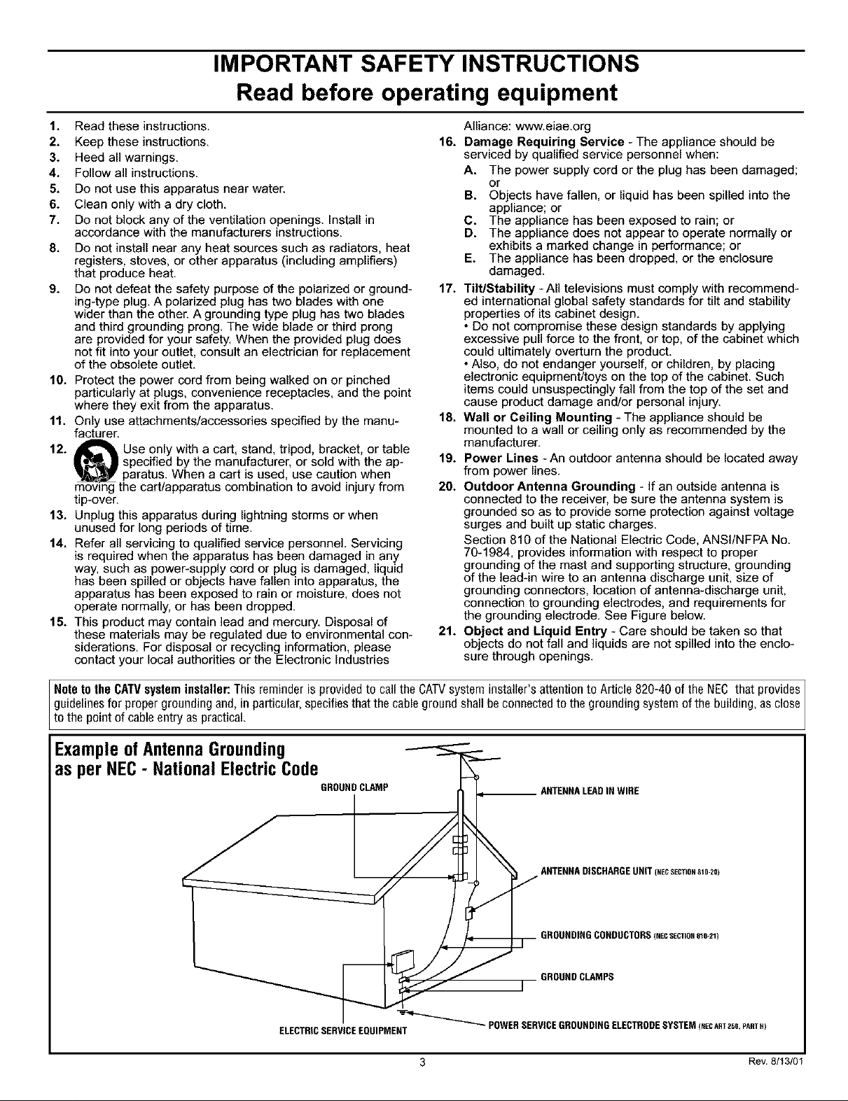
20. Outdoor Antenna Grounding - If an outside antenna is
connected to the receiver, be sure the antenna system is
grounded so as to provide some protection against voltage
surges and built up static charges.
Section 810 of the National Electric Code, ANSI/NFPA No.
70-1984, provides information with respect to proper
grounding of the mast and supporting structure, grounding
of the lead-in wire to an antenna discharge unit, size of
grounding connectors, location of antenna-discharge unit,
connection to grounding electrodes, and requirements for
the grounding electrode. See Figure below.
21. Object and Liquid Entry - Care should be taken so that
objects do not fall and liquids are not spilled into the enclo-
sure through openings.
Note to the CATVsysteminstaller: This reminder is provided to call the CATVsystem installer's attention to Article 820-40 of the NEC that provides ]
guidelines for proper grounding and, in particular,specifies that the cableground shallbe connected to the grounding system of the building, as close
to the pont of cab e entry as pract ca.
ExampleofAntennaGrounding
as per NEC- National ElectricCode
GROUND CLAMP
ELECTRICSERVICEEQUIPMENT
3 Rev. 8/13/01

INTRODUCTION
Welcome/Regislralion of Your TV .................... 2
Safety/Precautions .............................. 2-3
Features ........................................ 5
_ CONNECTING ACCESSORY DEVICES
TO YOUR TV
Panel Overview: Standard Inputs and Outputs ........... 6
Panel Overview: High-definition Inputs ................ 7
Connecting a VCR ................................ 8
Connecting a VCR and Cable Box .................... 9
Connecting and Using an Audio Hi-fi System
with Your TV ................................. 10
Making Optional Surround-sound Connections ......... 11
Connecting a Standard DVD Player .................. 12
Connecting an S-Video Device ..................... 13
Connecting a DVD Player with Progressive-scan
Capability .................................... 14
Connecting an HD Receiver to the
HD INPUT-AV 4 Jacks .......................... 15
Connecting a Camcorder .......................... 16
Connecting and Using Headphones
with Your TV ................................. 17
_ USING THE REMOTE CONTROL
Programming the TV Remote to Work
with Accessory Devices ..................... 18
Using the Code-entry Melhod to Program Your
TV Remote ................................... 19
Using the Search Method to Program Your
TV Remote ................................... 20
Direct-entry Codes for A/V Accessory Devices ...... 21-22
Using the TV Remote with Accessory Devices ......... 23
Using the AV and Source Select Buttons .............. 24
Using AutoSounO "M.............................. 25
Using AutoPicture TM ............................. 26
Using AutoSurff M ............................... 27
Using Program List and Alternate Channel (A/CH) ...... 28
Using the Sleep Timer Control ...................... 29
USING THE ON-SCREEN SUBMENUS
Selecting the Stereo/Mono Sound Mode .............. 38
Selecting the SAP (Second Audio Program) Feature ..... 39
Using the Bass Boost Control ...................... 40
_ FEATURES
The Timer
Setting the Clock ............................... 41
Displaying the Time ............................ 42
Setting the Timer's Start Time and Stop Time ......... 43
Selecting theTimer's Channel ..................... 44
Setting the Timer's Activate Control ................ 45
AutoLock TM
Understanding AutoLock TM ....................... 46
Setting up the AutoLock TM Access Code ............. 47
Using AutoLock TM to Block Channels ............... 48
Using AutoLock TM to Block by Movie Rating ......... 49
Using AutoLock TM to Block by TV Rating ........... 50
Turning the AutoLock TM Blocking Control
on or off .................................... 51
Using AutoLock TM to Block Unrated Broadcasts ....... 52
Using AutoLock TM to Block Broadcasts That
Have No Rating ............................... 53
Reviewing Your Currrent AutoLock TM Settings ........ 54
Using the Closed Captioning Control ................. 55
Using the Piclure-fonnat Control ................. 56-57
Using Active Control TM ........................... 58
APPENDIXES
Appendix A: Compatibility Information
for the TV's High-definition Inputs .......... 59
Appendix B: Model Specifications ................... 60
Appendix C: Setting Color Space for HD INPUT-AV 4 .... 61
Jim GENERAL INFORMATION
Care and Cleaning ............................... 62
Troubleshooting .............................. 63-64
Glossary of Television Terms ....................... 65
index ......................................... 66
Factory Service Locations ...................... 67-68
Limited Warranty ................................ 72
_ PICTURE
Adjusting the Picture Controls ............... 30
Setting the Eye Fidelity Control ..................... 31
Setting the Dynamic Contrast Control ................ 32
Adjusting the Manual Converge Controls:
Converge Red/Blue ............................. 33
Adjusting the Manual Converge Controls:
Multipoint Red/Blue ............................ 34
_ SOUND
Adjusting the Treble, Bass, and
Balance Controls ........................ 35
Using the AVL (Audio Volume Leveler) Control ........ 36
Selecting the Surround-sound Modes ................. 37
Refer to the simple Quick Use and Setup Guide (supplied with your
TV) for details on the following:
• Basic TV connections
• Television and remote-control operation
• On-screen menu conlrols
• Installation features.
Il",_ II"_ l'!'11,L_,Ik'_ ,"!ild,'Iftl Ik*i
As you unpack yourTV,please note that thisDirections'fi)r Use manual
contains mfety-tip information, the locations of factory-service centers, a
warranty re_Jslration card, remote control, and batteries for theremote
control. Please take a few minutes to complete yanr registration card. "llae
serial number for the TV is on the rear of the set. Refer to page 62 for
cleaning and care instructions.
4
Philips HD Optics gives extreme resolution HD with cutting-edge
processing and display technology. Includes a Philips wideband
video amplifier, microphosphor CRTs, hybrid projection lenses,
first-surface mirror, and fine-pitched lenticular screen.
Auto lntelliSens( rM Focus automatically adjusts picture conver-
gence at the push of a button. After reviewing a special test pat-
tern, optical sensors send position information to the controller,
which then corrects the pictures. Auto IntelliSense TM Focus
responds to the natural and man-made magnetic field conditions
where the TV is located, so you will always enjoy the best possible
picture.
Automatic Phosphor Aging Compensation (APAC) works with
the set's Automatic Format feature to prevent screen burn left by
nonmovthg images. Periodically, APAC automatically shifts your
television picture in very small increments, but in increments large
enough to blur image retention. APAC is like a screen saver for
your TV.
Active Control rM continuously measures and corrects all incoming
signals to provide the best picture settings. This feature provides a
sharp and virtually noise-free picture any time, from any NTSC
source. NTSC is the National Television Standards Committee for-
mat devised in the 1940s for TV broadcast analog video signals
(525 lines: 30 Hz).
Eye Fidelity gives you a choice between two different picture-
scanning techniques---progressive and interlaced. Progressive scan
doubles the number of visible picture lines per field by displaying
all picture frame lines at once, eliminating line flicker. The inter-
laced mode provides for a double vertical display (interlaced) of
progressive scan, which reduces annoying motion artifacts. The
Interlaced mode also helps smooth out jagged lines sometimes
seen on curved and angled surfaces.
Protective screen filter helps prevent accidental damage to the
delicate fi'ont lenticular screen. This filter has been specifically for-
mulated by Philips for HD displays to give the best possible pic-
ture and still protect your investment.
HD DVI and Component lnputs--DVi supports High-definition
Copy Protected digital video input for connection to compliant set-
top boxes. The HD component connection (Y Pb Pr or RGB +HV0
offers color purity, crisp color detail, and reduced color noise.
3-1) Y/C Digital Comb Filter (activated when using the tuner and
composite inputs) processes the video with spatial and temporal
filtering, virtually eliminating cross-color and cross-luminance
interference, improving video resolution. This filter uses extensive
memory to analyze complete video fields, significantly reducing
"dot crawl," "hanging dots," and "barber pole artitZacts '' on the
image.
Double-window, two-tuner Picture-in-Picture (PIP) allows you
to watch two shows, side by side. No VCR is necessary for tuning
PIP pictures. Your set's two separate tuners let you select two
shows anti display both in windows of equal proportion.
Virtual Dolby* Surround (referred to as Dolby Virtual in the
on-screen submenu) uses two speakers to simulate the surround
effect produced by a multichannel system.
Incredible Surround 'rM enhances stereo programs by making the
sound broader and fuller.
Center channel input, which has standard clip-on style speaker
connectors, simplifies the connection of surround-sound equipment
for optimal home-theater enjoyment. Since it contains the dialog
information, the center channel is vitally important to the overall
performance of any large screen in a home-theater system.
Home-cinema universal remote control operates your TV set and
other devices that work by infrared remote control, such as VCRs,
cable converter boxes, satellite receivers, and others. Note: You
may need to program the remote to work with devices other than
the TV. See pages 18--23.
Hi-fi stereo system, including a built-in audio amplifier aart a twin
speaker system with 2-inch tweeters and 5-inch woofers. The sys-
tem enables you to hear stereo sound or Second Audio Program
(SAP) bilingual broadcasts when they are available.
Audio/video jacks allow direct connections with VCRs and other
accessories for quality TV picture and sound playback. Component
video input jacks are provided for high-fidelity color and picture
resolution when using digital video source material, such as a DVD.
Audio Volume Leveler (AVL) control keeps the TV's sound at an
even level, Peaks and valleys that occur during program changes or
commercial breaks are reduced, making for a more consistent, com-
fortable sound.
AuloChron TM automatically sets the right time of day and main-
tains it with digital precision through brownouts, power tMlures,
and even Daylight Savings Time adjustments.
AuloLock TM protects young children from objectionable program-
ming with V-chip technology.
AuloSound TM allows you to select from three factory-set controls
anti a personal control that you set according to your own prefer-
ences through the on-screen Sound submenu. The three factory-set
controls---Voice, Music, and Theatre---enable you to tailor the TV
sound to enhance the particular programming you are watching.
AuloSurf _M allows you to easily switch among only the channels
that are of interest to you. You can program up to I0 channels into
the TV's AutoSurf TM memory through the on-screen display.
Channel Edit allows you to add or remove channels from the list
of channels stored in the TV's memory. Channel Edit makes it easy
to limit or expand the number of channels that are available to you
when you press the CH +/-- buttons on your remote control.
Closed Captioning allows you to read TV program dialog or voice
conversations as on-screen text.
Dynamic Contrast helps sharpen the picture quality by making the
contrast between the dark and bright picture areas more noticeable
as the image on screen changes.
_ determined this product meets the Energy Stai® guidelines Ihr
Active Control, APAC, AutoPicture, AutoSound, AutoSurI, Incredible
Surround, mid IntelliSense are trademarks of Philips Consumer Electronics
Noith America. Copyright © 2003 Philips Consumer Electronics.
*Mmmfactured under license from Dolby Laboratories. "Dolby" and _he
double-D symbol are trademarks of Dolby Laboratories.
As an Energy Star® Partner, Philips Consumer Electronics has
energy efficiency. Energy Star® is a U.S. registered mark. Using
products wilh the Energy Star® label can save energy. Saving
energy reduces air pollution and lowers utility bills.
Your new projection television aart its packaging contain materials
that can be recycled and reused. Specialized companies can recy-
cle your product to increase the amount of reusable materials anti
minimize the amounts that need to be properly disposed. The bat-
teries used by your product should not be thrown away when
depleted but should be handed in and disposed of as small chemi-
cal waste. Please find out about the local regulations concerning
how to dispose of your old television, batteries, and packaging
materials whenever it is time to replace them.

Connecting Accessory Devices toYourTV
}z_u can connect a wide range of video and
udio devices to your TV,in various ways.
Thispage and the next one provide an overview
_?fsignal compatibilities and the &pes of
devices'you can connect to thejacks.
Connection examples jbllow on subsequent
pages. See pages 1 and 2 of the Quick Use and
Setup Guide that came with your setjbr exam-
ples of basic conneetions. Youmay also want to
refer to the user instructions that came with
each particular device jbr ir!ibrmation on con-
neetions.
WhatYou Can Connect to the
Standard Panel Jacks
ANTENNA IN 75_ jack--use to con-
nect radio-frequency (RF) signals from
VHF/UHF antennas or a cable system.
These are 480i signals.
A_T_A_ ] _PS_TCH _ Rearof TV
YPbPr (component video input [CVI]jacks)--compatible with 480i signals
only. Use to connect accessories having
component video outputs, such as DVD
players, laser-disc players, video-game
players, satellite receivers, or other
devices. Use the INPUT-AV 1 L(elt) and
R(ight) AUDIO jacks for sound connec-
tions. CVI is not accessible in the PIP
window.
S-VIDEO (super video)jacks--com-
3
patible with 480i signals only. Use to
connect accessories having Super VHS
(S-VHS) outputs, such as VCRs, DVD
players, laser-disc players, video-game
players, satellite receivers, or other
devices.
VIDEO (composite)jacks (INPUT-AV 1,
4
INPUT-AV 2, and TV's side jack panel
[AV3])--compatible with 480i signals
only. Use to connect accessories having
composite video outputs, ,such as VCRs,
video-game players, or other devices.
AUDIO inputs (INPUT-AV 1,
INPUT-AV 2, and TV's side jack panel
[AV3])--use to connect from the audio
output jacks on VCRs, DVDs, or other
accessories.
OUTPUT (VIDEO/AUDIO)--video is
compatible with 480i signals only. Use to
connect to aVCR to record programs
from the TV. Or use the AUDIO outputs
to connect to an audio hi-fi system.
AMP SWITCH, CENTER
CHANNEL AMP INPU"I,and
SUBWOOFER Output--use to make
optional surround-sound connections
(,seepage 11).
_, Headphone jack--use to connect
headphones for personal listening.
Summary of signal compatibilities
Compatible output signal
from an external source
TV Input or device
ANTENNA IN 75fL INPUT AV-1,YPbPr
(component video inputs[CVI]), 480i (480 lines, interlaced)
INPUT AV-2,and side jack panel (AV3)
Signal sources connected to the
HD INPUT-AV 4 or HD INPUT-AV 5 jacks
Side JackPane_ [_
will provide the best picture (see page 7 for
descriptions of those inputs). Among the
standard (480i-compatible) inputs
ANTENNA IN 75f2, INPUT AV-I, CVI
labeled Y, Pb, Pr], INPUT AV-2, and the
side jack panel [AV3]) the best picture
will come from signal sources connected to
the CVI jacks. S-Video will provide the
next-best level of picture quality.
ii ii!ii!!!ii ii!i !i i i !!iii i i!
NOTE:The
TV recognizes
the sidejack
panelasAV3.
The side jack-panel inputs (recognized by the
TV as AV3) are convenient for connecting a
camcorder, See page 16.

WhatYou Can Connect to the
High-definition Input Jacks
HD INPUT--AV 4--use to connect dig-
ital equipment with a 1080i or a 480p
signal output, such as HD receivers
(1080i or 480p) or DVD players wilh
progressive-scan capability (480p). You
can connect equipment with YPbPr
component video or RGB outputs to
the HD INPUT-AV 4jacks. H and V
sync connections may or may not be
required for RGB connections. (See
page 59.) Dedicated audio input jacks
are localed with the HD INPUT-AV 4
video jacks.
NOTE: The Picture-in-Picture (PIP)
feature is not available for use wilh AV 4.
Connecting Accessory Devices toYourTV
Rear of TV
HI) INPUT-AV 5--use to connect digi-
2
tal equipment with DVI (digital video
interface) 1080i or 480p output. DVI is
a specific digital input allowing
encrypted transmission ofuncom-
pressed HD content. DVI includes
HDCP (high-bandwidth digital content
protection), which is supported by
Hollywood, satellite providers, and
most of the consumer electronics indus-
try. DVI is gaining momentum and
quickly becoming an industry standard
for the consumer to view high-definition
material while keeping content protected.
NOTE: The Picture-in-Picture (PIP)
feature is not available for use with AV5.
HD INPUT-AV 4 480p (480 lines,progressive scan)
HD INPUT-AV 5 480p (480 lines,progressive scan)
!iii! iiiii !i!i¸!ii !i!iiiiiii!¸!!iiii!!!iiii i ili i!i!i !iiii!il¸ii!iill¸ii!iiiiiiiiiN¸ i !iiiii IH! iiiiii!i¸ii!ii!iill¸ii!ilili i!iiiiiii! ill¸iiiiiiii ii!i!i i¸i!iiii¸I¸i!iiiiiiii!i!iiii!
• The TV's default color-space setting for HD
fNPUT-AV4 isYPbPr. If the picture looks
grossly incorrect,try changing the color-space
setting on either the digital equipment or the
TV. For more information on set_ng the color
space on the digital equipment, see the equip-
ment's direclions-for-use manual. To set the
TV's color space, see page 61 in this manual.
• This television is designed to be compatible
with high-definition signal standards 1080i
and 480p as specified by the Elec_onic
IndustriesAssociation standard EIA770.3.
Because output standards may vary by manu-
facturer, you may encounter some digital
equipment thaiwill not properly display pic-
tures on the TV.
• The PIP (Pic_e-in-picture) feature allowsyou
to tuneto a programin themainwindowand
scanother channelsinthe PIPwindow,Froma
single antennaorcableinput, signalsare separat-
ed intotwo signals withinthe television,The
AV 1, AV2, andAV3ir_uts are alsoavailableas
PIPsources.
Summary of signal compatibilities
Compatible output signal
from an external source
TV Input or device
1080i (1080 lines, interlaced) or
Digital video interface (DVI) with
1080i (1080 lines, interlaced) or
i!i!i!,iiiiii i iiiiiiiiill¸ii!i¸II II¸ii il¸!i!i!iiii!i!i!iiii!i!i!iiii!i!i!iiii!i!i!iiii!i!i! i !ilN i! i !i!! i¸ii!!;ii ii iiiii i¸i!iiiiiiii!iiiiiii!iiiiiii!iiiiiii!iiiiiii!iiiiiii!iiill
Because DVt is such new technology, the
electronics industry is still working toward a
decision on one standard, Philips testing has
determined that compatibility issues exist wilh
respect to a limited number of high-definition
receivers when they are connected to the DVI
input on this television, if you should experi-
ence difficulties, please contact our Customer
Care Center at 1-800-531-0039.
Connecting Accessory Devices toYourTV
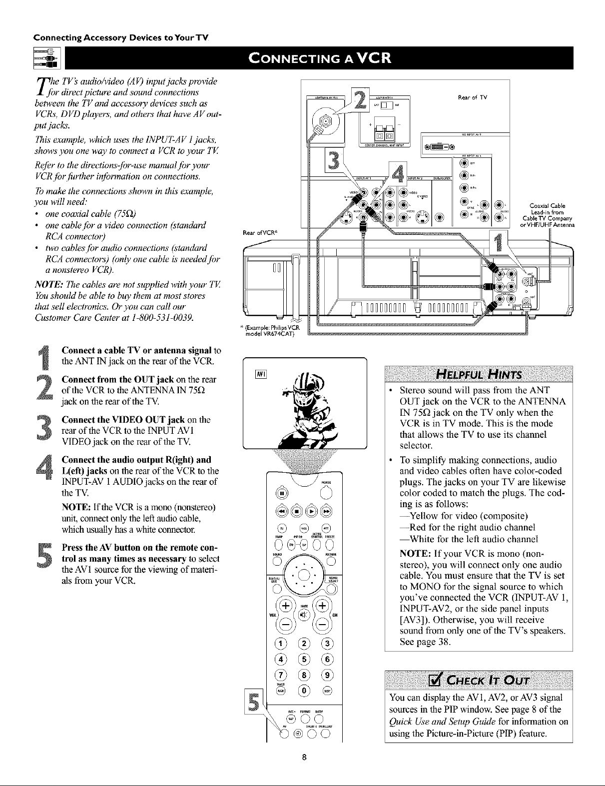
Tjhe TV's audio/video (AF) input jacks provide
r directpicture and sound connections
between the TV amt accessory devices such as'
VCRs, DVD players, and others that have AV out-
put jacks.
This"example, which uses the INPUT-AV l jacks,
shows you one way to connect a VCR to ),our TE
Re[Or to the directions-jbr-use manual /br your
VCRjbr f!_rther in/brmation on connections.
To make the connections shown in this example,
you will need:
• one coaxial cable (75_)
• one cablejbr a video connection (standard
RCA connectoO
• two cables/br audio connections (standard
RCA connectors) (only one cable is neededjbr
a nonstereo VCR).
NOTE: The cables are not supplied with your TV.
You should be able to buy them at most stores
that sell electronics. Or you can call our
Customer Care Center at 1-800-531-0039.
Connect a cable TV or antenna signal to
the ANT IN jack on the rear of the VCR.
Connect from the OUT jack onthe rear
of the VCR to the ANTENNA IN 75D
jack on the rear of the TV.
Connect the VIDEO OUT jack on the
rear of the VCR to the INPUT AVI
VIDEOjack on the rear of the TV.
Connect the audio output R(ight) and
L(eft) jacks on the rear of the VCR to the
INPUT-AV 1AUDIO jacks on the rear of
the TV.
NOTE: if the VCR is a mono (nonstereo)
unit, connect only the left audio cable,
which usuallyhas a white connector.
Press the AV button on the remote con-
trol as many times as necessary to select
the AV1 source for the viewing of materi-
als from your VCR.
Rear ofVCR*
* (Example: Philips VCR
model VR674CAT)
[]
Rear of TV
Coaxial Cable
Lead-in from
C_ble TV Company
or VHF/UHF Antenna
Stereo sound will pass from the ANT
OUT jack on the VCR to the ANTENNA
IN 75_ jack on the TV only when the
VCR is in TV mode. This is the mode
that allows the TV to use its channel
selector.
To simplify making connections, audio
and video cables often have color-coded
plugs. The jacks on your TV are likewise
color coded to match the plugs. The cod-
ing is as follows:
--Yellow for video (composite)
--Red for the right audio channel
_hite for the left audio channel
NOTE: If your VCR is mono (non-
stereo), you will connect only one audio
cable. You must ensure that the TV is set
to MONO for the sigual source to which
you've connected the VCR (INPUT-AV 1,
INPUT-AV2, or the side panel inputs
[AV3]). Otherwise, you will receive
sound from only one of the TV's speakers.
See page 38.
You can display the AV1, AV2, or AV3 signal
sources in the PIP window. See page 8 of the
Quick Use and Setup Guide for information on
using the Picture-in-Picture (PIP) feature.
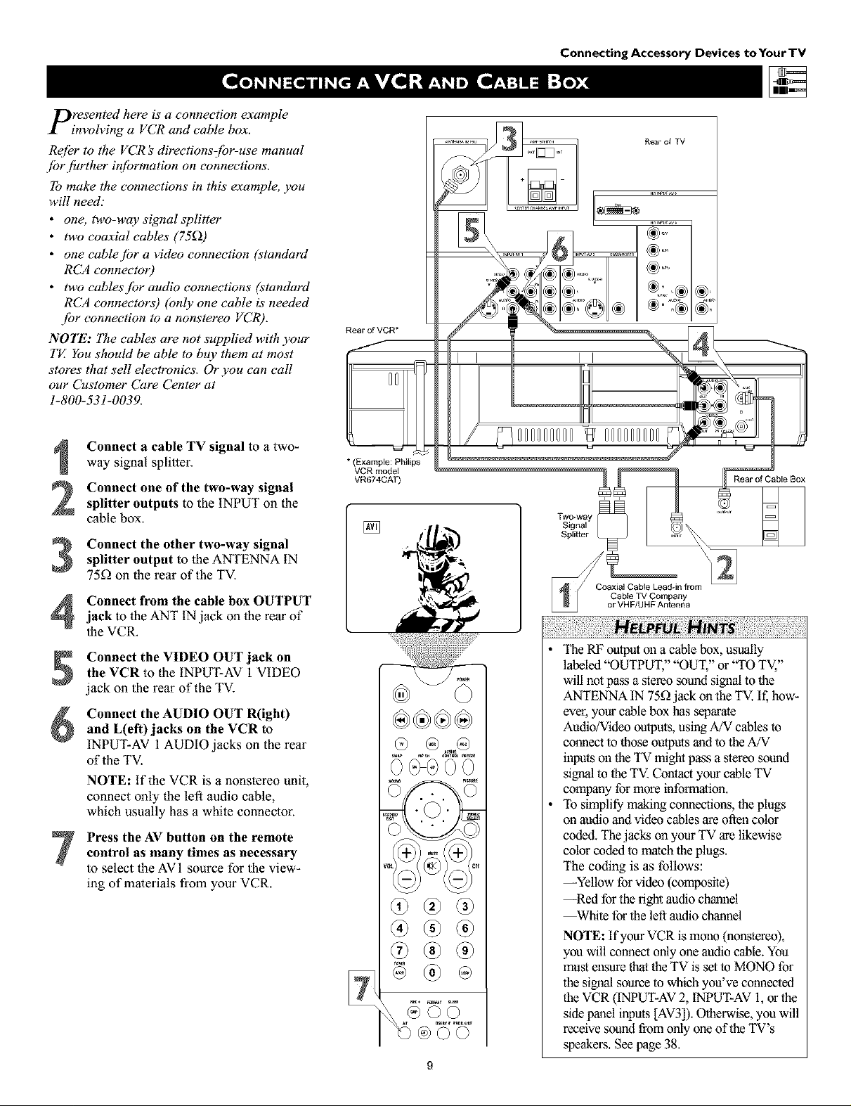
presented here is a connection example
involving a VCR and cable box.
Re[_r to the VCR _ directionsCbr-use manual
.[br fhrther #_[brmation on connections.
To make the connections in this example, you
will need."
• one, two-way signal splitter
• two coaxial cables' (75_))
• one cablejbr a video connection (standard
RCA connectoO
• two cablesjbr audio connections (standard
RCA connectors) (only one cable is' needed
.[br connection to a nonstereo VCR).
NOTE: The cables are not supplied with your
TE You should be able to buy them at most
stores that sell electronics. Or you can call
our Customer Care Center at
1-800-531-0039.
Connect a cable TV signal to a two-
way signal splitter.
Connect one of the two-way signal
splitter outputs to the INPUT on the
cable box.
Connect the other two-way signal
3
splitter output to the ANTENNA IN
75_ on the rear of the TV.
Rear of VCR*
/
J
* (Example: Philips
VCR model
VR674CAT)
[]
Connecting Accessory Devices toYourTV
Rear of TV
I I
i
/
000000000 000000000
Rear of Cable Box
Connect from the cable box OUTPUT
4
jack to the ANT IN jack on the rear of
the VCR.
Connect the VIDEO OUT jack on
the VCR to the INPUT-AV 1 VIDEO
jack on the rear of the TV.
Connect the AUDIO OUT R(ight)
and L(eft)jacks on the VCR to
INPUT-AV 1AUDIO jacks on the rear
of the TV.
NOTE: If the VCR is a nonstereo unit,
connect only the left audio cable,
which usually has a white connector.
Press the AV button on the remote
control as many times as necessary
to select the AVI source for the view-
ing of malerials from your VCR.
• The RF outputoll a cable box, usually
labeled "OUTPUT," "OUT," or "TO TV,"
will not pass a stereo sound signal to the
ANTENNA IN 75£2jack on the TV. If, how-
ever, your cable box has separate
Audio/Video outputs, using A/V cables to
comlecl to those outputs and to the A/V
inputs on the TV might pass a stereo sound
signal to the TV. Contact your cable TV
company for more information.
• To simplify making counections, the plugs
on audio aud video cables are often color
coded. The jacks on your TV are likewise
color coded to match the plugs.
The coding is as follows:
--Yellow for video (composite)
--Red for the fight audio channel
_hite forthe left audio chaunel
NOTE: If your VCR is mono (hOt,stereo),
you will connect only one audio cable. You
mus'tensure that the TV is set to MONO for
the sigoal source to which you've connected
the VCR (INPUT-AV2, INPUT-AV 1,or the
side panel inputs [AV3]). Otherwise, you will
receive sound from only one of the TV's
speakers. See page 38.
Connecting Accessory Devices to Your TV
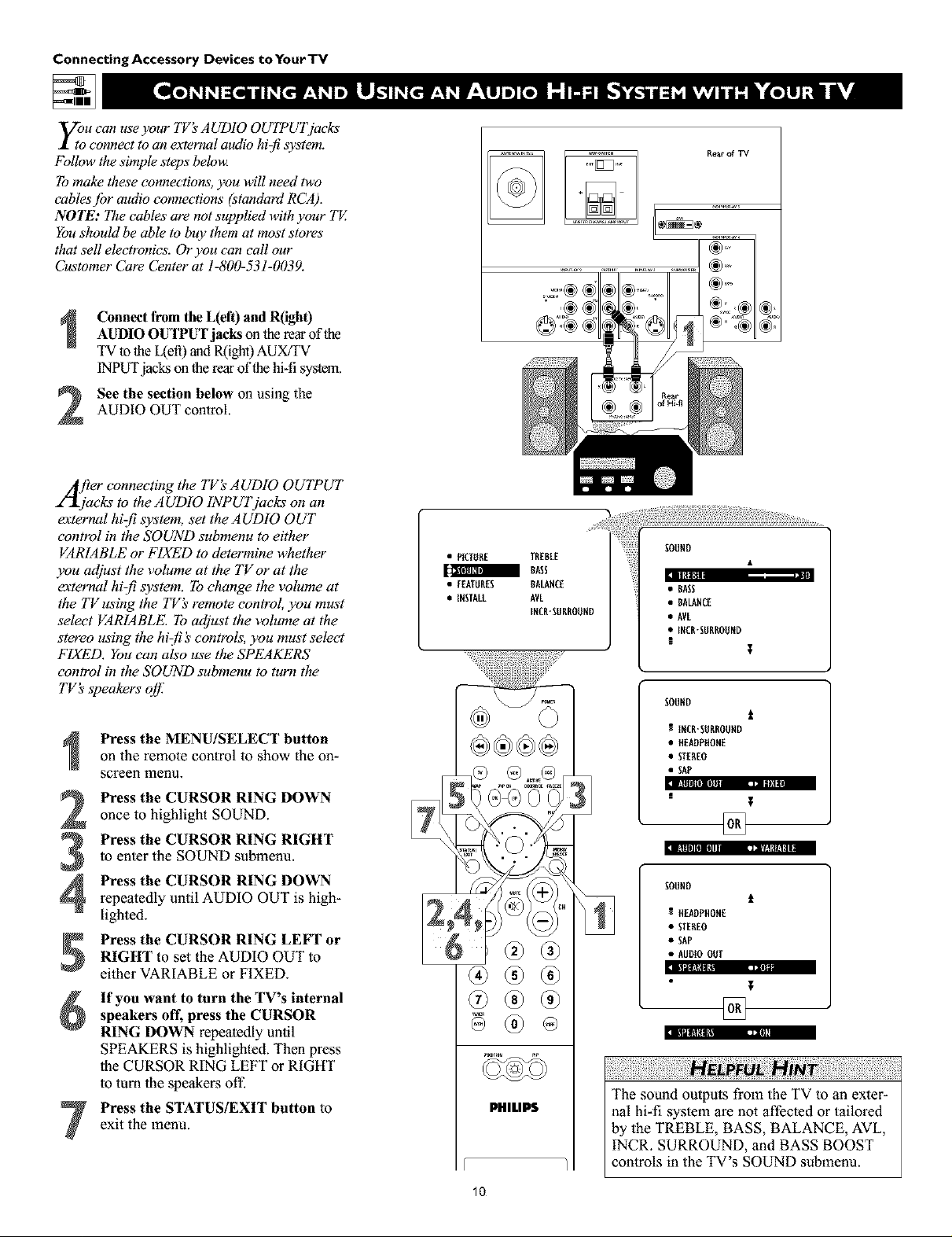
y;u can use your TV's AUDIO OUTPUTj_cks
connect to an external audio hi:fi system.
Follow the simple steps belou_
To make these connections, you will need two
cables jbr audio connections (standord RCA).
NOTE: The cables are not supplied with your TV.
You should be able to buy them at most stores"
that sell electronics. Or you can call our
Customer Care Center at 1-800-531-0039.
Connect from the L(eft) and R(igh0
AUDIO OUTPUT jacks on the rear of the
TV to the L(efi) and R(ight) AUX/TV
INPUT jacks on the rear of the hi-fi system.
See the section below on using the
AUDIO OUT control.
2
/frier connecting the TV_ AUDIO OUTPUT
2"_jacks to the AUDIO INPUTjacks on an
external hiz[i system, set the AUDIO OUT
control in the SOUND submenu to either
VARIABLE or FIXED to determine whether
you adjust the volume at tile TVor at the
external hi-fi system. To change the volume at
the TVusing the TV_ remote control, you must
select VARIABLE. To adjust the volume at the
stereo using the hizf! _'controls, you must select
FIXED. You can also use the SPEAKERS
control in the SOUND submenu to turn the
TV's speakers off:
Press the MENU/SELECT button
on the remote control to show the on-
screen menu.
Press the CURSOR RING DOWN
once to highlight SOUND.
Press the CURSOR RING RIGHT
to enter the SOUND submenu.
Press the CURSOR RING DOWN
4
repeatedly until AUDIO OUT is high-
lighted.
Press the CURSOR RING LEFT or
RIGHT to set the AUDIO OUT to
either VARIABLE or FIXED.
If you want to turn the TV's internal
speakers off, press the CURSOR
RING DOWN repeatedly until
SPEAKERS is highlighted. Then press
the CURSOR RING LEFT or RIGHT
to turn the speakers off-
Press the STATUS/EXIT button to
exit the menu.
• PICTURE TREBLE
I BASS
• EEATURES BALANCE
• IESTALL AVL
IECR-EUBROUED
®
PHILIPS
• BALANCE
• AVL
• IXCR-EUBROUND
I
SOUND
R INCB-SURBOUHD
• HEADPffOHE
• STEREO
• SAP
II!lll|l[I] rill--- ,_=, II
I!llll][III_ ,i,/.'l Ill|
SOUHD
HEADPHOHE
• STEREO
• SAP
• AUDIOOUT
illl_lill , •
The sound outputs from the TV to an exter-
nal hi-fi system are not affected or tailored
by the TREBLE, BASS, BALANCE, AVL,
INCR. SURROUND, and BASS BOOST
controls in the TV's SOUND submenu.
T
t
t
,m
10

_nur TV has extra jacks that allow you to con-
ect to an external audio amplifier system and
apowered s_bwoojbl: This connection option will
provide a surrouud-souud eaperience similar to a
movie theater or concert hall.
To make the connectioas shown in this example,
you will need."
• two cablesjbr audio connections (standard
RCA connectors)
• jburpaired wiresjbr speaker connections
• one cablejbr a subwoq/er connection
(standard RCA connectors).
NOTE': The cables are not supplied with your TV.
You should be able to buy them at most stores"
that sell electronics. Or you can call our
Customer Care Center at 1-800-531-0039.
Connect from the Center Speakers out-
putjacks on the amplifierwith DolbyPro
Logic*or Dolby Digital to the correspon-
ding CENTER CHANNEL INPUTjacks on
lberear of theTV.Place the TV's AMP
switchin the EXT (external)position.
FrontSpeakers
Connecting Accessory Devices to Your TV
Rear Speakers
!
Rear of Amplifier with Dolby Pro Logic or Dolby Digital
Rear of Powen_d Subwoo_r
R_r of_
Connect from the L(eft) andR(ight)AUDIO OUTPUT jacks on therear of the
TV to the L(efi) and R(ight) TV IN jacks on
Powered Subwoofer
therear of the Dolby receiver.
Connect from the receiver's front andsurround speakerconnectors to thefront
and rear surround speakers.
Connect from the SUBWOOFER outputjack on therear oftbe TV to the L(efi)and
R(ight)Low Level Inputjacks on therear of
thepowered subwoofer.
Set the TV'sAUDIO OUT control to
FIXED. See page 10.
The diagram below, fight shows how to arrange the
speakers and subwoofer for surround sound.
NOTE:The graycircte indicatesthe primary wewing area
Surround-sound Setup
TV
(CenterSpeakef_)
Fr°nt _ Front
Speaker Speaker
!i¸i!iii!i!!iiiii!iiiiiiii!ili!i¸iii!ili!ili!!i¸iiil¸ii!i¸ii!ili!ili!ili!ili!ili!iiiifl i ! !!!i!i ¸i i iiiiiii!ii iiiiiiiiiiiiiiiii!iiiiiii!iiiiiiii!iiiiiii!iiiiiii!iiiiiii!i
• if you use a single cable to make the connec-
tion to the powered subwoofer, yoa will need
to increase the volume on the back of the
subwoofer to compensate for the absence of
the second cable.
• You must adjust the trim of the powered sub-
woofer at the powered subwoofer. Trim refers
to the fine adjustments of volume level.
*"Dolby', "Pro Logic", and the double-D symbol are
trademarks of Dolby Laboratories.
Rear Rear
Speaker Speaker

Connecting Accessory Devices to Your TV
Component video inputs allow the highest pos-
ible color and picture resolution in the play-
back of digital signals, such as those of DVD
players. I_e color dzTJbrence signals (Pb, Pr) and
the luminance (Y) signal are connected and
received separately. I_e result is better color
bandwidth iq[brmation than is possible with com-
posite video (labeled VIDEO on your TV'sjack
panel) or S- Vzdeo connections.
To make the connections shown in this example,
you will need:
• three cablesjbr video connections (standard
RCA connectors)
• two eablesjbr audio connections (standard
RCA connectors).
NOTE: The cables are not supplied with your TV.
You should be able to buy them at most stores"
that sell electronics. Or you can call our
Customer Care Center at 1-800-531-0039.
Connect the YPbPr (component)
VIDEO OUT jacks from the DVD player
to the INPUT-AV 1 YPbPr (component
video) jacks on the rear of the TV.
NOTE: The INPUT-AV 1 YPbPr jacks
will accept 480i (interlaced) output sig-
nals only. The connection example on this
page assumes the use ofa DVD player
with interlaced output. Some DVD play-
ers, howevel; have YPbPr outputs that can
be switched between interlaced and pro-
gressive scan. If you are attempting to use
a DVD player with progressive-scan
(480p outpu0 capability to make the con-
nection shown in this example, you must
be sure to switch the DVD player to inter-
laced. If necessary, refer to the DVD play-
er's directions-for-use manual for help. If
you want to use the DVD player in pro-
gressive-scan mode, you must use the
HD INPUT-AV 4 jacks (see page 14).
Connect the AUDIO OUT L(eft) and
R(ight) jacks from the DVD player to the
INPUT-AV 1AUDIO jacks on the rear of
the TV.
Press the AV button on the remote con-
trol as many times as necessary toselect
the CVI (component video input) source
on the TV for the viewing of materials
from your DVD player.
*(Example: Phi_ips DVD model DVD712)
[]
Rear of TV
ii!ili iii! i!ii i il¸!I ¸iiiiii!ii!i!i!ili!i!i!ili!i!i!iiii!i!iiii!i!ili!i¸!iil
• To simplify making conneclions, the con-
nectors on audio and video cables are often
color coded. Tbe jaclcs on your TV are like-
wise color coded to match the connectors.
• The names fur the component video jacks
may differ depending on the DVD player or
accessory digital source equipment used.
For example, besides YPbPr, you may see
R-Y/B-Y/Y; or CrCbY. Althougb abbrevia-
lions and terms may vary, the letters B and
R stand for the blue and red color compo-
nent signal connectors, respectively, and Y
indicates the luminance signal. If necessary,
refer to the direclions-for-use manual for
your DVD or digital accessory for more
infonnalion.
• You can also connect a satellite receiver to
the TV in a manner similar to the example
shown on this page. If you connect a ,satel-
lite receiver to the TV, you will need to use
the receiver's channel-memorization system
to store channels in the receiver's memory.
• if you experience difficulties receiving
,sound with a DVD disc, check the ,sound
setlings through the DVD disc's menu.
• CVI is not accessiNe in the PIP window.
See page 8 in the Quick Use and Setup
Guide for more on the PIP feature.
To prevant uneven picture-tube aging, do not
leave nonmoving images or picture borders on
the screen for an extanded period. See page 62.
12
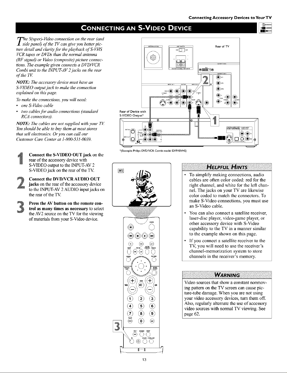
rrThe S(uper)-Video connection on the rear (and
_1 side panel) of the TV can give you better pic-
ture detail and elarity.[br the playback ql'S-VHS
VCR tapes or DVDs than the normal antenna
(RF signal) or Video (composite) picture connec-
tions, The example given connects a DVD/VCR
Combi unit to the 1NPUT-AV 2 jacks on the rear
ol'the TV.
NOTE': I_e accessory device must have an
S-VIDEO output jack to make the connection
eaplained on this page.
To make the connections, you will need."
• one S-_deo cable
• two cablesjbr audio connections (standard
RCA connectors).
NOTE': lae cables" are not supplied with your TE
You should be able to buy them at most stores"
that sell electronics. Or you can call our
Customer Care Center at 1-800-531-0039.
Connecting Accessory Devices to Your TV
Rear of TV
,=,:o®®
..........
I
Rear of Device with
S-VIDEO Output*
Connect the S-VIDEO OUT jack on the
rear of the accessory device with
S-VIDEO output to the [NPUT-AV 2
S-VIDEO jack on the rear of the TV.
Connect the DVD/VCRAUDIO OUTjacks on the rear of the accessory device
to the [NPUT-AV2 AUDIO inputjacks on
the rear of the TV.
Press the AV button on the remote con-trol as many times as necessary to select
the AV2source on the TV for the viewing
of materials from your S-Video device.
*(Example: I_lilips DVDNCR Combi mode_ DV910VHS)
To simplify making connections, audio
cables are often color coded: red for the
right channel, and white for the left chan-
nel. The jacks on your TV are likewise
color coded to match the connectors. To
make S-Video connections, you must use
an S-Video cable.
You can also connect a satellite receiver,
laser-disc player, video-game player, or
other accessory device with S-Video
capability to the TV in a manner similar
to the example shown on this page.
if you connect a satellite receiver to the
TV, you will need to use the receiver's
channel-memorization system to store
channels in the receiver's memory.
:iii! i iiii !i!i¸!i i !i! iiiiiii!¸!!iiii!!!iiii i ili i!i!i !ili i!il¸ii!i ill¸ii!iiii iiii!i!i,iii!!ill¸ii¸!iiiiiii!i!i!il¸ii i i ii i ¸II IIII¸iiii !i!iiiii!i!i ii:ii:iiii i!iii,i¸II! !III¸ii!iiii iiii!i!i,lii! !ill¸ii¸!iiiiiii!i!i!i,lii! !ill¸ii¸!iiiiiii!i!i!i,i ii! ill
Video sources tha_show a constant nonmov-
ing pattern on the TV screen can cause pic-
ture-tube damage. When you are not using
,our video accessory devices, turn them oft:
Also, regularly allemate the use of accessory
video sources with normal TV viewing. See
page 62.
Connecting Accessory Devices toYourTV
Z hejbllowing instructions explain how to
onnect a D VD player with progressive-scan
capability to the HD INPUT-AV 4 jacks on
):our TV.
To make the connections, you will need:
• three cablesjbr video connections (standard
RCA connectors)
• two cables[br audio connections (standard
RCA connectors).
NOTE: The cables are not supplied with ):our TE
You should be able to buy them at most stores"
that sell electronics. Or you can call our
Customer Care Center at 1-800-531-0039.
Connect from the YPrPb jacks on
the rear of the DVD player to the
HD INPUT-AV 4 G/Y, R/Pr, B/Pb jacks
on the rear of the TV.
Connect from the L(eft) and R(igh0
2
AUDIO OUT jacks on lhe rear of the
DVD player 1othe HD INPUT-AV4
AUDIO L(eft)andR(ight)jacks on the rear
of theTV.
Make sure the DVD player is in pro-
gressive-sean mode. You will not get a
3
viewable picture through the HD
INPUT-AV 4 jacks if the DVD player is
in interlaced mode.
For more information on placing your
DVD player in progressive-sean mode,
see the DVD player's directions-for-use
manual. Also, see the Helpful Hints to
the right. The way in which progres-
sive-scan mode is selected varies among
DVD players.
Press the AV button on your TV remote
4
control as many times as necessary to
select the AV4 signal source for the view-
ing of materials from your progressive-
scan DVD player.
If you experience difficulties receiving
sound with a DVD disc, check the sound
settings through the DVD disc's menu.
To prevant uneven picture-tube aging, do not
leave nonmoving images or picture borders on
the screan for an extended period. See page 62.
+%
R_ar of DVD Player with Progressive-scan Capability
®
@
if after connecting your DVD player your
display is filled with wavy lines, it may be
that your DVD player is not set to progres-
sive-scan mode. Some DVD players have an
I/P (interlaced/progressive scan) switch
located on the back or front of the players for
changing from interlaced to progressive-scan
mode. Other DVD players may allow the
mode to be changed by pressing a button on
the DVD player's remote control or by using
the DVD player's on-screen menu. If the
interlaced/progressive-sean selection
option is provided only through the DVD
on-sereen menu, you will need to connect
the DVD player to another AV input
source in addition to HD INPUT-AV 4 to
see the DVD menu. Select this additional
AV source on screen to see the DVD menu
and choose progressive-sean mode. You
will then be able to see the DVD picture
through the AV4 source.
Some DVD players have dedicated progres-
sive-scan output jacks that are labeled as
such and require no switching to provide a
picture through the HD INPUT-AV4 jacks.
See your DVD player's directions-for-use
manual for information.
The default color-space selling for the
HD INPUT-AV 4 jacks is YPbPr. RGB is
also an option. If the picture's color looks
grossly incorrect, try changing either the
DVD player's or TV's color-space setting.
See the DVD player's directions-for-use
manual for information on setting its color
space. Or see page 61 in this manual to set
the TV's color space.
The Picture-in-Picture(PIP) feature does
not function with AV4 or AV5.
14
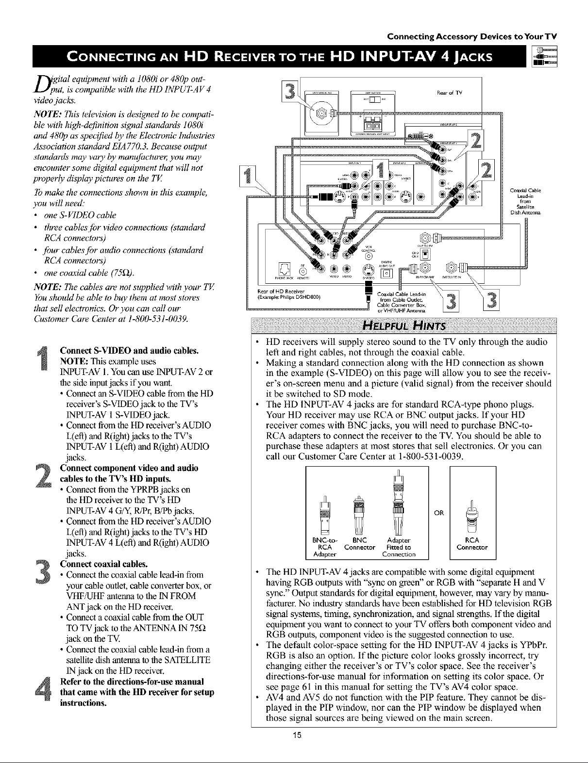
D;gital equipment with a 1080i or 480p out-
ut, is compatible with the HD INPUT-A V 4
video jacks.
NOTE: This television & designed to be compati-
ble with high-definition signal standards 108(h"
and 480p as specified by the Electronic" Industries
Association standard EIA 770.3. Because output
standards may vary by manufbcture_ you may
encounter some digital equipment that will not
properly display pictures on the TV.
To make the connections shown in this example,
you will need."
• one S-VIDEO cable
• three cablesjbr video connections (standard
RCA connectors)
• jbur cablesjbr audio connections (standard
RCA connectors)
• one coaxial cable (75_2).
NOTE: The cables are not supplied with your TE
You should be able to buy them at most stores"
that sell electronics. Or you can call our
Customer Care Center at 1-800-531-0039.
Connecting Accessory Devices toYourTV
Coaxr_ Cable
Lea_*in
fiom
_atel[ite
Dish Antenna
Connect S-VIDEO and audio cables.
NOTE: Thisexample uses
INPUT-AV1.You canuseINPUT-AV2or
the side inputjacks if you want.
• Connect an S-VIDEO cable fromtheHD
receiver's S-VIDEO jack to the TV's
INPUT-AV1S-VIDEOjack.
• Connect from the HD receiver's AUDIO
L(ett) and R(ight)jacks to the TV's
INPUT-AV 1L(eft) and R(ight) AUDIO
jacks.
Connect component video and audiocables to the TV's HD inputs.
• Connect from theYPRPB jacks on
the HD receiver to the TV's HD
INPUT-AV4 G/Y,R/P1;B/Pb jacks.
• Connect from the HD receiver's AUDIO
L(efl) and R(ight)jacks to the TV's HD
INPUT-AV4 L(eft) and R(ight) AUDIO
jacks.
• Connect the coaxial cable lea&in from
Connect coaxial cables.
your cable outlet, cable converter box, or
VHF/UHF antenna to the tN FROM
ANTjack on the HD receiver.
• Connect a coaxial cable from the OUT
TO TV jack to the ANTENNA IN 75_
jack on the TV.
• Connect the coaxial cable lea&in from a
satellite dish antenna to the SATELLITE
INjack on the HD receiver.
Refer to the directions-for-use manualthat came with the HD receiver forsetup
instructions.
• HD receivers will supply stereo sound to the TV only through the audio
left and right cables, not through the coaxial cable.
• Making a standard connection along wilh the HD connection as shown
in 1he example (S-VIDEO) on this page will allow you to see the receiv-
er's on-screen menu and a piclure (valid signal) from the receiver should
it be switched to SD mode.
• The HD INPUT-AV 4 jacks are for standard RCA-type phono plugs.
Your HD receiver may use RCA or BNC oulput jacks. If your HD
receiver comes with BNC jacks, you will need to purchase BNC-to-
RCA adapters to connect the receiver to the TV. You should be able to
purchase these adapters al most stores that sell electronics. Or you can
call our Customer Care Center at 1-800-531-0039.
OR
BNC-to- BNC Adapter
RCA Connector Fitted to
Adapter Connection
RCA
Connector
• The HD INPUT-AV4 jacks are compatible wilh some digital equipment
having RGB oulputs with "sync on greeff' or RGB with "separate H and V
sync." Output standards for digital equipment, however, may vary by manu-
facturer. No industry standards have been established for HD television RGB
signal systems, liming, synchronization, and signal strengths. If the digital
equipment you want to comlect 1oyour TV offers both component video and
RGB outputs, component video is the suggesmd conneclion 1ouse.
• The default color-space setting for the HD INPUT-AV 4 jacks is YPbPr.
RGB is also an option. If the piclure color looks grossly incorrect, try
changing either the receiver's or TV's color space. See the receiver's
directions-for-use manual for information on setting its color space. Or
see page 61 in this manual for setting the TV's AV4 color space.
• AV4 and AV5 do not function with the PIP feature. They cannot be dis-
played in the PIP window, nor can the PIP window be displayed when
those signal sources are being viewed on the main screen.
15

Connecting Accessory Devices toYourTV
T[bhe side panel jacks provide a convenient way
r you to connect a camcorder to your TE
The side panel jacks are recognized by your TV
asAV3.
You can obtain S- VIDEO quality with an S- VHS,
Hi-8, or digital camcorder by connecting to the
S- VIDEO input instead o['the VIDEO (composite)
input.
To make the connections shown in this example,
you will need:
• an S-VIDEO cable
• two eables[br audio connections (standard
RCA connectors).
NOTE: The cables are not supplied with your TE
You should be able to buy them at most stores
that sell electronics. Or you can call our
Customer Care Center at 1-800-531-0039.
Connect from the S-VIDEO output on
the camcorder to the S-VIDEO input in
the TV's side panel.
Connect from the AUDIO outputs on
the camcorder to the side panel AUDIO
L(efi) and R(ight) inputs.
Press the AV button on the remote con-
3
trol as many times as necessary to select
the AV3 source on the TV.
Turn the camcorder on, insert a video-
4
tape and press PLAY to view the tape
on the TV.
To simplify making connections, lhe con-
nectors on audio cables are often color
coded: red for the right channel, and white
for the left channel. The jacks on your TV
are likewise color coded to match the con-
nectors. To make S-Video connections, you
must use an S-Video cable.
®®®®
@ ®
®®®
®®®
®®®
16
Connecting Accessory Devices to Your TV
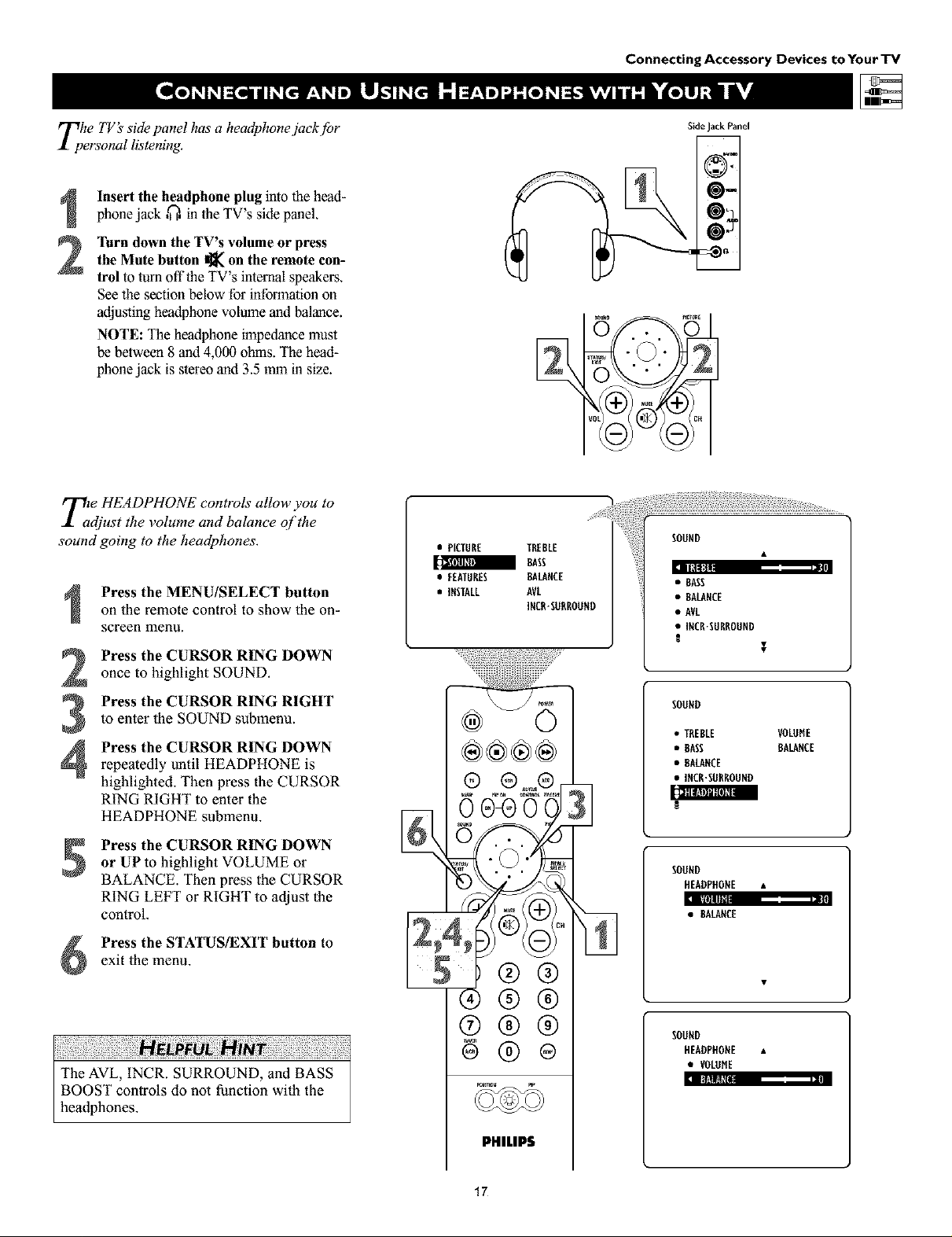
Tphe TV's side panel has a headphonejack.[br
ersonal listening.
Insert the headphone plug into the head-
phone jack ,_, in the TV's side panel.
Turn down the TV's volume or press
the Mute button I]_ on the remote con-
2
trol to turn offtbe TV's internal speakers.
See the section below for information on
adjusting headphone volume and balance.
NOTE: The headphone impedance must
be between 8 and 4,000 ohms. The bead-
phone jack is stereo and 3.5 mm in size.
T2e HEADPHONE controls allow you to
djust the volume and balance qf the
sound going to the headphones.
Press the MENU/SELECT button
on the remote control to show the on-
screen menu.
Press the CURSOR RING DOWN
once to highlight SOUND.
Press the CURSOR RING RIGHT
to enter the SOUND submenu.
Press the CURSOR RING DOWN
4
repeatedly until HEADPHONE is
highlighted. Then press the CURSOR
RING RIGHT to enter the
HEADPHONE submenu.
• PICTURE TREBLE
a BASS
• FEATURES BALANCE
• INSTALL AVL
INCR"SURROUND
®®®®
0 04) 0
SideJackPanel
@=
• BASS
• BALANCE
• AVL
• INCR'SURROUND
SOUND
• TREBLE VOLOHE
• BASS BALANCE
• BALANCE
• INCR'SORROUND
[l_lllS_lllll l|llIIII
Press the CURSOR RING DOWN
or UPto highlight VOLUME or
BALANCE. Then press the CURSOR
RING LEFT or RIGHT to adjust the
control.
Press the STATUS/EXIT button to
exit the menu.
The AVL, INCR. SURROUND, and BASS
BOOST controls do not function with the
headphones.
5Z;®Q
®®®
®@®
6®®
PHILIPS
17
SOUND
HEADPHONE •
:l IIllllllll|
• BALANCE
/1/
SOUND
HEADPHONE •
• VOLUME
:l II}'.tltl_[Bll
Using the Remote Control
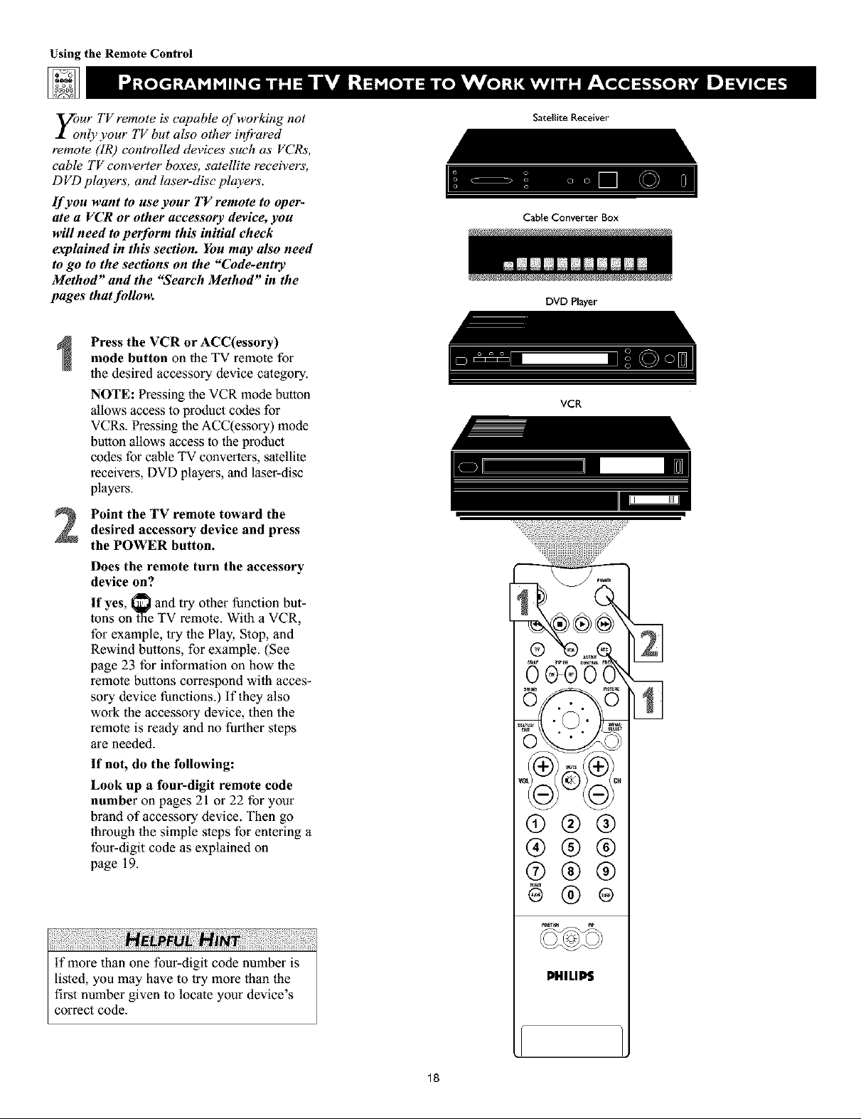
y;ur TV remote is capable of working not
nly your TV but also other ir!fi'ared
remote (IR) controlled devices such as VCRs,
cable TV converter boxes, satellite receivers,
D VD players, and laser-disc players'.
If you want to use your TV remote to oper-
ate a VCR or other accessory device, you
will need to perform this initial check
explained in this section. You may also need
to go to the sections on the "Code-entry
Method" and the "Search Method" in the
pages that fidlom
Press the VCR or ACC(essory)
mode button on the TV remote for
the desired accessory device category.
NOTE: Pressing the VCR mode button
allows access to product codes for
VCRs. Pressing llle ACC(essory) mode
bullon allows access to the product
codes for cable TV conveners, satellite
receivers, DVD players, and laser-disc
players.
Satellite Receiver
Cable Converter Box
DVD Player
VCR
Point the TV remote toward thedesired accessory device and press
the POWER button.
Does the remote turn the accessory
device on?
If yes, _ and try other function but-
tons on _laeTV remote. With a VCR,
for example, try the Play, Stop, and
Rewind buttons, for example. (See
page 23 for infonnalion on how lhe
remote buttons correspond wi_h acces-
sory device functions.) If they also
work the accessory device, then the
remote is ready and no further steps
are needed.
If not, do the following:
Look up a four-digit remote code
number on pages 21 or 22 for your
brand of accessory device. Then go
through the simple steps for entering a
four-digit code as explained on
page 19.
®®®
®®®
®®®
@®®
if more lhan one four-digit code number is
listed, you may have to try more than the
first number given to locate your device's
correct code.
PHILIP$
18
Using the Remote Control
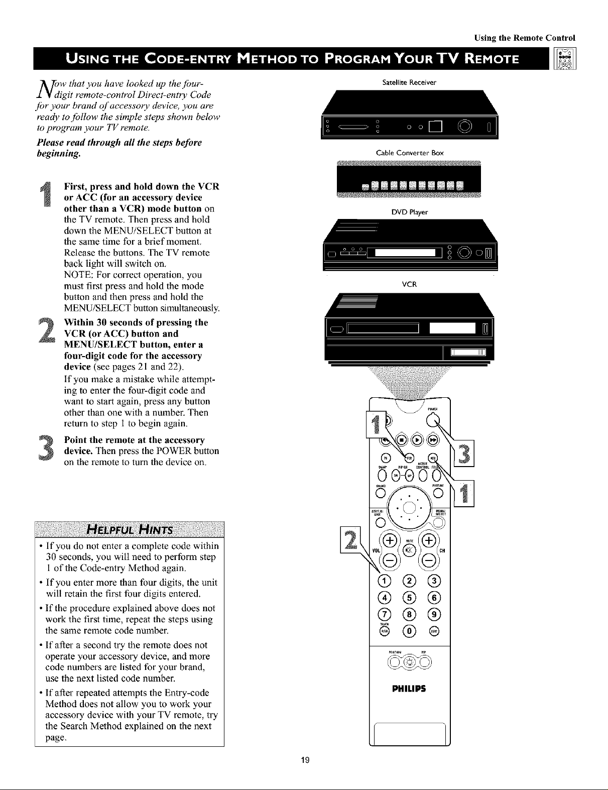
NOdW that you have looked up the [bur-
igit remote-control Direct-entry Code
ibr your brand of accessory device you are
ready to jbllow the simple steps shown below
to program your TV remote.
Please read through all the steps before
beginning.
First, press and hold down the VCR
or ACC (for an accessory device
other than a VCR) mode button on
the TV remote. Then press and hold
down the MENU/SELECT button at
the same time for a brief moment.
Release the buttons. The TV remote
back light will switch on.
NOTE: For correct operation, you
must first press and hold the mode
button and then press and hold the
MENU/SELECT button simultaneously.
Within 30 seconds of pressing the
2
VCR (or ACC) button and
MENU/SELECT button, enter a
four-digit code for the accessory
device (see pages 21 and 22).
if you make a mistake while attempt-
ing to enter the four-digit code and
want to start again, press any button
other than one with a nmnber. Then
return to step 1 to begin again.
Satellite Receiver
CaNe Converter Box
DVD Player
Imm_m_m m_mnmnm I
VCR
Point the remote at the accessorydevice. Then press the POWER button
on the remote to tuna the device on.
If you do not enter a complete code within
30 seconds, you will need to perform step
1 of the Code-entry Method again.
If you enter more than four digits, the unit
will retain the first four digits entered.
If the procedure explained above does not
work the first time, repeat the steps using
the same remote code nmnber.
• If after a second try the remote does not
operate your accessory device, and more
code nmnbers are listed for your brand,
use the next listed code number.
• If after repeated attempts the Entry-code
Method does not allow you to work your
accessory device with your TV remote, try
the Search Method explained on the next
page.
®@@
@@@
®@@
PHILIP$
19
Using the Remote Control
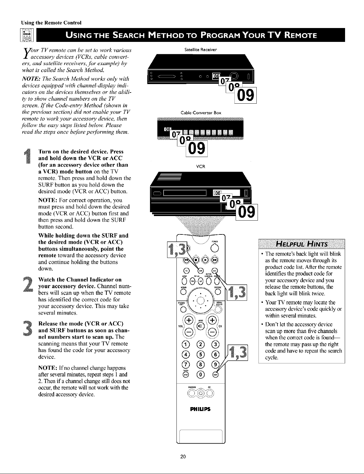
your TV remote can be set to work various
ccessory devices (VCRs, cable convert-
ers, and satellite receivers, fbr example) by
what is called the Seareh Method.
NOTE: The Search Method works only with
devices equipped with channel-display indi-
cators on the devices themseh_es or the abili-
ty to show channel numbers on tile TV
screen, if'the Code-entry Method (shown in
the previous section) did not enable your TV
remote to work your accessory device, then
jbllow tile easy steps listed below_ Please
read the steps once be[bre peffbrming them.
Turn on the desired device. Press
and hold down the VCR or ACC
(for an accessory device other than
a VCR) mode button on the TV
remote. Then press and hold down the
SURF button as you hold down the
desired mode (VCR or ACC) button.
NOTE: For correct operation, you
must press and hold down the desired
mode (VCR or ACC) button first and
then press and hold down the SURF
button second.
While holding down the SURF and
the desired mode (VCR or ACC)
buttons simultaneously, point the
remote toward lhe accessory device
and continue holding the bu_ons
down.
Watch the Channel Indicator on
2
your accessory device. Channel num-
berswill scan up when the TV remote
has identified the correct code for
your accessory device. This may take
several minutes.
Release the mode (VCR or ACC)
and SURF buttons as soon as chan-
3
nel numbers start to scan up. The
scanning means that your TV remote
has found the code for your accessory
device.
NOTE: If no channel change happens
after several minutes, repeat ,_eps 1 and
2. Then ifa channel change still does not
occur, the remote will not work with the
desired accessory device.
Satellite Receiver
Cable Converter Box
VCR
®®®
®®®
®
The remote's back light will blink
as the remote moves through its
product code list. After the remote
identifies the product code for
your accessory device and you
release the remote buttons, the
back light will blink twice.
YourTV remote may locate the
accessory device's code quickly or
within several minutes.
Don't let the accessory device
scan up more thau tive chmnlels
whenthe correctcode is foun_
the remote may pass up the right
code andhave to repeat the search
cycle.
2O
PHILIPS

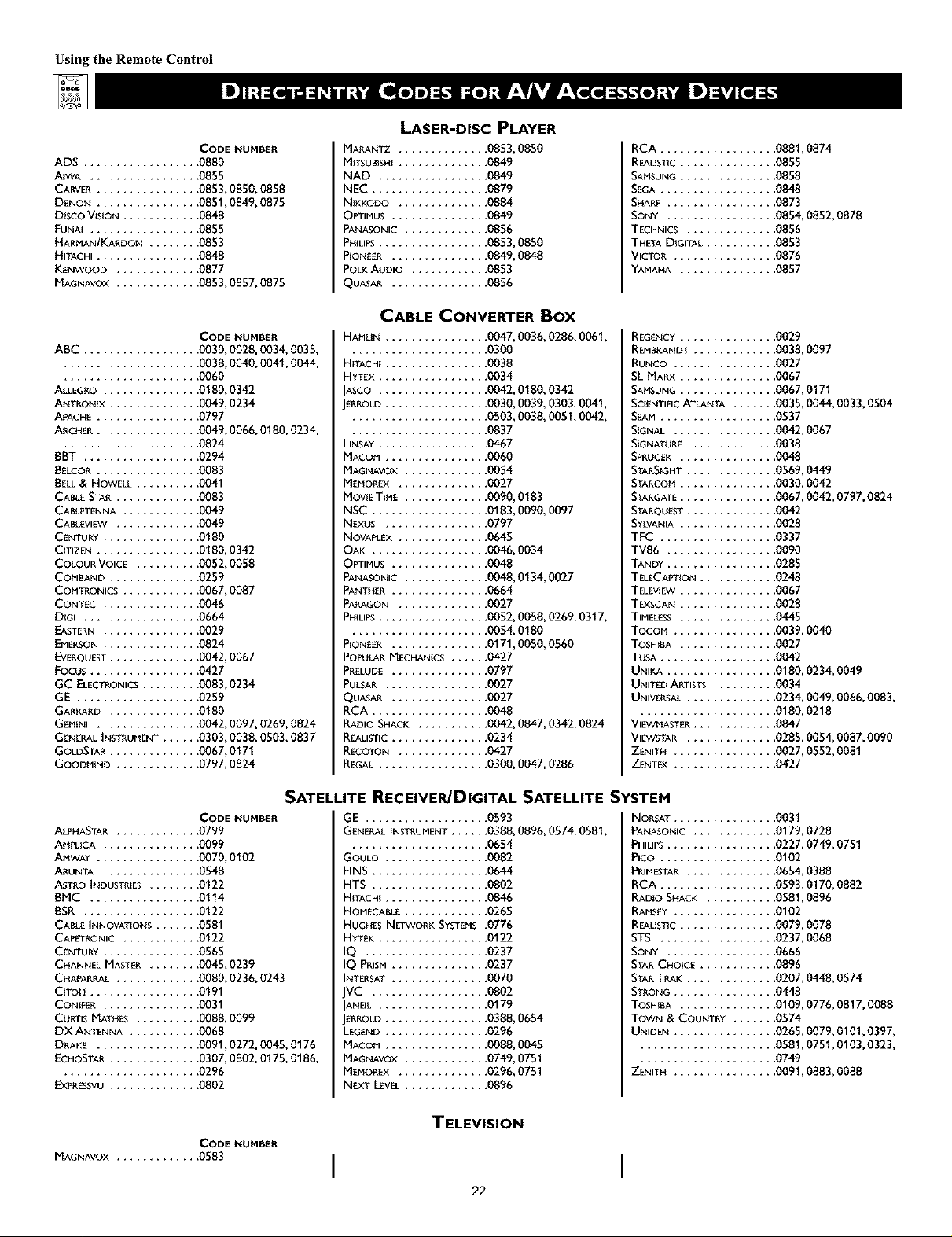
ADMI_[ ............... 0075, 0236
ADVENTURA ............. 0027
AJKO .................. 0305
AIWA ................. 0334, 0495, 0027, 0064
AKAI .................. 0133, 0080, 0068, 0076,
..................... 0088, 0183, 0269
AMERICA A_'ION ....... 0305
AMERICAN H_GH ........ 0062
ASHA ............... 0267
AUDIOVOX ............ 0064
BEAUMARK ............ 0267
BELL & HOWE_ ........ 0131
BROKSON_C ........... 0148, 0211, 0029, 0236,
..................... 0238, 0322, 0388, 0506
CCE ............
CALIX ...........
CANON ..........
CAPEHART ........
CARVER ..........
C_NERAL.........
C{TIZEN ..........
COLT ...........
CRAIG ...........
CODE NUMBER
.... 0099, 0305
.... 0064
.... 0194, 0062, 0129
.... 0047
.... 0108
.... 0305
.... 0305, 0064
.... 0099
.... 0064, 0099, 0074, 0267,
..................... 0298
CURTIS MATH_S ....
CYIBERNEX ........
DAEVVOO .........
DAYTRON ........
DENON ..........
DYNATECH ........
ELECTROHOME .....
ELECTROPHONIC ....
EMEREX ..........
EMERSON .........
.... 0062, 0068, 0087, 0189
.... 0078, 0267
.... 0305, 0588, 0047, 0072
.... 0047
.... 0069
.... 0027
.... 0064
.... 0064
.... 0059
.... 0211,0029, 0236, 0305,
..................... 0063,0148,0238,0588,
..................... 0235,0321,0506,0088,
..................... 0115,0239,0027,0064,
..................... 0070,0095,0322,0388,
..................... 0537
FISHER................. 0074,0131,0081,0093
F_I ................... 0060,0062
FUNAI ................. 0027
GE ................... 0062,0087,0075,0092,
..................... 0229,0267
GARRARD.............. 0027
GOVIDEO .............. 0306, 0459, 0553, 0259
GOLDSTAR .............. 0064, 0045, 0065, 0498,
..................... 0507
GRADIENTE .......
GRUNDIG .........
HI-Q ...........
HARLEY DAVlDSON ..
HARMAN/KARDON , .
HARWOOD .......
HEADQUARTER .....
HITACHI ..........
.... 0035, 0027, 0435
.... 0222
.... 0074
.... 0027
.... 0065, 0102, 0108
.... 0095, 0099
.... 0073
.... 0069, 0193, 0132, 0092,
..................... 0027, 0068, 0109
HUGHESNEI_VORKSYSTEMS.0069
JVC .................. 0094,0035, 0233, 0234,
..................... 0068, 0411
JENSEN ............
KEC .............
KLH .............
KENWOOD .........
KODAK ...........
LXI ..............
LLOYD'S ...........
LOGIK ............
MEI .............
MGA ............
MGN TECHNOLOGY ....
MTC ..............
MAGNASONIC .........
MAGNAVOX ..........
MAGNIN ............
MARANTZ ...........
MARTA ..............
MATSUSHITA ..........
MEMOREX .........
MINOLTA ..........
M_SUB_SHI .........
MOTOROLA .........
MULTITECH .........
NAD ............
NEC .............
N_KKO............
NIKON ...........
NOBLEX ..........
OLYMPUS ..........
OPTIMUS..........
OPTON_CA .........
ORION ...........
PANASONIC .........
PENNEY ...........
PENTAX ...........
PHILCO...........
PHILIPS ............
PILOT ............
PIONEER..........
POLK AUDIO .........
PORTLAND ...........
PROFITRONIC.........
PROSCAN ............
PROTEC.............
PULSAR .............
QUARTER............
VCR
.0068
.0064,0305
.0099
.0068,0094,0411,0065
.0062,0064
.0064
.0027,0235
.0099
.0062
.0070,0088,0267
.0267
.0027,0267
.0305
.0062,0108,0137,0130,
.0027,0066,0176
.0267
.0108,0062
.0064
.0062,0189,0481
.0131,0074,0506,0027,
.0064,0075,0062,0073,
.0267,0334,0066,0189,
.0236,0481,0828,0829
.0132,0069
.0200,0088,0102,0241,
.0269,0070,0075,0094,
.0470
.0062,0075
.0027,0099
.0085
.0065,0067,0068,0077,
.0094,0109,0131
.0064
.0061,0280
.0267
.0062,0253
.0189,0481,0827,0828,
.0075,0085,0829,0064,
.0131,0459
.0089
.0506,0029,0211,0236,
.0322
.0062,0189,0828,0481,
.0253,0104,0405,0829,
.0129,0252,0254,0273,
.0827
.0062,0267,0064,0069,
.0065,0067,0081
.0069,0092,0132
.0062,0236,0506
.0108,0062,0089,0137,
.0830,0831
.0064
.0085,0195,0094
.0108
.0047
.0267
.0087,0229
.0099
.0066,0078
.0073
Using the Remote Control
QUAR_ ....
QUASAR....
......... 0073
......... 0062,0189,0104,O481,
......... 0828
RCA .......
......... 0087,0176,0229,0069,
......... 0132,0085,0062,0075,
......... 0092,0104,0133,0267,
......... 0304
RADIO SHACK
RADIX ......
RANDEX ....
REAUST{C....
......... 0027
......... 0064
......... 0064
......... 0027,0131,0074,0075,
......... 0064,0062,0089,0073,
......... 0093
RICOH......
RUNCO.....
STS .......
SALORA .....
SAMSUNG ....
SANKY ......
SANSUI .....
......... 0061,0280
......... 0066
......... 0069
......... 0102
......... 0072,0078,0080,0267
......... 0066,0075
......... 0068,0506,0027,0094,
......... 0109,0236,0298
SANYO ......
SCOTT......
......... 0074,0073,0131,0267
......... 0211,0238,0148,0070,
......... 0072,0237,0239
S_ARS......
......... 0081,0132,0064,0069,
......... 0027,0062,0073,0074,
......... 0093,0131
SEMP.......
SHARP ......
SH_NTOM ....
SHOGUN ....
SINGER .....
SONY ......
......... 0072
......... 0075,0089
......... 0099
......... 0078,0267
......... 0099
......... 0060,0061,0059,0280,
......... 0027,0038,0062
SUNPAK .....
SYLVANIA ....
......... 0280
......... 0062,0108,0027,0070,
......... 0130,0137
SYMPHONIC ..
TMK ......
TATUNG.....
TEAC.......
TECHNICS ...
TEKNIKA ....
THOMAS....
TOSHIBA ....
......... 0027
......... 0063,0235,0267
......... 0068
......... 0027,0068
......... 0062,0189,0273
......... 0027,0062,0064,0079
......... 0027
......... 0072,0237,0239,0070,
......... 0093,0393
TOTEVlS_ON ..
UNITECH ....
VECTOR .....
VECTOR RESEARCH........ 0065, 0067
VIDEO CONC_rs ......... 0067, 0072, 0088, 0248
VIDEOSONIC ............. 0267
WARDS ................ 0062,0087,0089,0027,
..................... 0074,0239,0267,0069,
..................... 0075,0099,0108,0176
WHITEWESTINGHOUSE ..... 0099,0305,0236
XR-1000 .............. 0099,0027,0062
YAMAHA ............... 0065
ZENITH ................ 0066,0027,0060,0061,
..................... 0236,0506
......... 0064,0267
......... 0267
......... 0072
DENON ................ 0859
GE ................. 0862
HARMAN/KARDON ...... 0871
HITACHI .............. 0870
JVC ................ 0868
KENWOOD ........... 0865
MAGNAVOX ........... 0860
CODE NUMBER
DVD PLAYER
MARANTZ .......... 0866
MrrSUBISHI .......... 0861
ONKYO ............ 0860
OPTIHUS ........... 0869
PANASONIC .......... 0859
PHILIPS............. 0866, 0860
P_ONEER ........... 0869, 0863
PROSCAN ........... 0862
21
RCA ................ 0862,0869
SAHSUNG ............. 0870
SONY ............... 0864
TECHNICS ............ 0859
THETADIGITAL ......... 0869
TOSHIBA ............. 0860
YAMAHA ............. 0859,0867
ZENITH .............. 0872,0860
SEE THE NEXT PAGE FOR MORE CODES.
Using the Remote Control
ADS ............
AIWA ...........
CARVER ..........
DENON ..........
Disco VISION ......
FUNA{ ...........
HARMAN/KARDON , .
HITACHI ..........
KENWOOD .......
MAGNAVOX .......
CODE NUMBER
.... 0880
.... 0855
.... 0853, 0850, 0858
.... 0851,0849, 0875
.... 0848
.... 0855
.... 0853
.... 0848
.... 0877
.... 0853, 0857, 0875
CODE NUHBER
ABC .................. 0030, 0028, 0034, 0035,
..................... 0038, 0040, 0041,0044,
..................... 0060
ALLEGRO ............... 0180, 0342
ANTRON{X .............. 0049, 0234
A_ACHE................ 0797
ARCHER................ 0049, 0066, 0180, 0234,
..................... 0824
BBT ............
BELCOR..........
BELL & HOWELL ....
CABLE STAR .......
CABLETENNA ......
CABLEVIEW .......
CENTURY .........
C{TIZEN ..........
COLOUR VOICE ....
COMBAND ........
COMTRONICS ......
CONT_C .........
DIGI ............
EASTERN .........
EMERSON .........
EVERQUEST ........
FOCUS...........
GC ELECTRONICS . . .
GE .............
GARRARD ........
GEMINI ..........
GENERAL INSTRUMENT
GOLDSTAR ........
GOODMJND .......
.... 0294
.... 0083
.... 0041
.... 0083
.... 0049
.... 0049
.... 0180
.... 0180,0342
.... 0052,0058
.... 0259
.... 0067,0087
.... 0046
.... 0664
.... 0029
.... 0824
.... 0042,0067
.... 0427
.... 0083,0234
.... 0259
.... 0180
.... 0042,0097,0269,0824
.... 0303,0038,0503,0837
.... 0067,0171
.... 0797,0824
LASER-DISC PLAYER
MARANTZ .........
MITSUBISH{ .........
NAD ............
NEC .............
NIKKODO .........
OPTIMUS ..........
PANASONIC .........
PH{LIPS............
P_ONEER ..........
POLKAUDIO .........
QUASAR ............
CABLE CONVERTER Box
HAMUN .............
HiTACHi ...........
HYTI:×............
JASCO ............
JERROLD ...........
LINSAY ............
MACOM...........
MAGNAVOX .........
MEMORFX .........
MOVIET{ME .........
NSC .............
N_xus ...........
NOVAPLEX .........
OAK .............
OPTIMUS ..........
PANASONIC .........
PANTHER ..........
PARAGON .........
PHILIPS ............
P_ONEER..........
POPULARMECHANICS . .,
PRELUDE ............
PULSAR .............
QUASAR ............
RCA ...............
RADIO SHACK ........
REALISTIC ............
RECOTON ...........
REGAL ..............
.0853,0850
.0849
.0849
.0879
.0884
.0849
.0856
.0853,0850
.0849,0848
.0853
.0856
.0047,0036,0286,0061,
.0300
.0038
.0034
.0042, 0180, 0342
•0030, 0039,0303, 0041,
•0503, 0038,0051,0042,
.0837
.0467
.0060
.0054
.0027
.0090,0183
.0183,0090,0097
.0797
.0645
.0046,0034
.0048
.0048,0134,0027
.0664
.0027
.0052,0058,0269,0317,
.0054,0180
.0171,0050,0560
.0427
.0797
.0027
.0027
.0048
.0042,0847,0342,0824
.0234
.0427
.0300,0047,0286
RCA .......
REAU_{C ....
SAMSUNG ....
SEGA .......
SHA_ ......
SONY ......
TECHNICS .,.
THETA DIGITAL
VICTOR .....
YAMAHA ....
REGENCY ............... 0029
REMBRANDT ............. 0038,0097
RUNCO ................ 0027
SL MARX ............... 0067
SAHSUNG ............... 0067,0171
SCIENTIFICATLANTA ....... 0035,0044,0033,0504
SEAM .......
SIGNAL .....
SIGNATURE . ..
SPRUCER ....
STARSIGHT . ..
STARCOM ....
STARGATE ....
STARQU_ST . . .
_YLVANIA ....
TFC .......
TV86 ......
TANDY ......
TEL_CAPT_ON.
TEL_V_EW ....
TEXSCAN ....
TIMELESS ....
TOCOM.....
TOSHIBA ....
TUSA .......
UNI,<A......
UNITED ARTISTS
UNIVERSAL . ..
......... 0881,0874
......... 0855
......... 0858
......... 0848
......... 0873
......... 0854,0852,0878
......... 0856
......... 0853
......... 0876
......... 0857
......... 0537
......... 0042,0067
......... 0038
....... 0048
....... 0569,0449
....... 0030,0042
....... 0067,0042,0797,0824
....... 0042
....... 0028
......... 0337
......... 0090
......... 0285
......... 0248
......... 0067
......... 0028
......... 0445
......... 0039,0040
......... 0027
......... 0042
......... 0180,0234,0049
......... 0034
......... 0234,0049,0066,0083,
................... 0180,0218
VIEVVMASTER ........... 0847
VIEVVSTAR ............ 0285,0084,0087,0090
ZENITH .............. 0027,0552,0081
ZENTEK .............. 0427
ALPHASTAR ........... 0799
AMPLICA ............. 0099
AI'IWA¥ .............. 0070,0102
ARUNTA ............. 0548
ASTRO INDUSTRIES ...... 0122
BMC ............... 0114
BSR .................. 0122
CABLE INNOVATIONS .
CAPETRONIC ......
CENTURY .........
CHANNEL MASTER , .
CHAPARRAL .......
C{TOH ...........
CONIfeR .........
CURTIS MATH_S ....
DX ANTENNA .....
DRAKE ..........
ECHOSTAR ........
..................... 0296
CODE NUMBER
.... 0581
.... 0122
.... 0565
.... 0045,0239
.... 0080,0236,0243
.... 0191
.... 0031
.... 0088,0099
.... 0068
.... 0091,0272,0045,0176
.... 0307,0802,0175,0186,
EXPRESSVU.............. 0802
MAGNAVOX ............. 0583
CODE NUMBER
SATELLITE RECEIVER/DIGITAL SATELLITE SYSTEM
GE ................
GENERAL INSTRUMENT . . ,
GOULD .............
HNS ...............
HTS ...............
HITACHI .............
HOMECABLE ..........
HUGHES NETWORK SYSTEMS
HYTEK............
IQ ..............
IQ PRISM..........
INTERSAT ..........
JVC .............
IANEIL ............
JERROLD ...........
LEGEND ...........
MACON ...........
MAGNAVOX .........
MEMOR_ .........
N_XTLEVEL..........
.0593
.0388, 0896, 0574,0581,
.0654
.0082
.0644
.0802
.0846
.0265
.0776
.0122
.0237
.0237
.0070
.0802
.0179
.0388, 0654
.0296
.0088, 0045
.0749,0751
.0296,0751
.0896
NORSAT .....
PANASONIC ..
PHILIPS......
PICO .......
PRIMESTAR. ..
RCA .......
RADIO SHACK
RAMSEY .....
REALIST{C....
STS .......
SONY ......
STARCHOICE .
STARTRAK ...
STRONG .....
TOSHIBA ....
TOWN & COUNTRY ....... 0574
UNIDEN ................ 0265,0079,0101,0397,
..................... 0581,0751,0103,0323,
..................... 0749
ZENITH ................ 0091,0883,0088
TELEVISION
I I
22
......... 0031
......... 0179,0728
......... 0227,0749,0751
......... 0102
......... 0654,0388
......... 0593,0170,0882
......... 0581,0896
......... 0102
......... 0079,0078
......... 0237,0068
......... 0666
......... 0896
......... 0207,0448,0574
......... 0448
......... 0109,0776,0817,0088

Time CTmrt below provides you with corn-
on accessory-device junctions associat-
ed with the buttons on your Philips TV remote
control. (Seepages 18 20jbr #![brmation on
programming your TV remote to operate
accessory devices.)
NOTES:
• Functions can vary according to the manu-
jacturer 's spec!f!eations jbr each accessory
deviee.
• First press the VCR mode button to use the
TV remote to operate a VCR.
• First press the A CC mode button to use the
TV remote to operate a DVD player, laser-
dise playeg cable converter box, or satel-
lite receiver/digital satellite system.
®
® @o,.@
ICURSORRING UP
[CURSOR RING LEFT L__
INU"OERO° oo <O-9> ®
-®
®
INCH_TVNCR___®
Using the Remote Control
-------JFASTFORWARD I
_RING RIGHT]
_CUR_ORR,NGOOWq
@@
@@
@®
@®
®®®®
@ @
iV Remote VC R
and Accessory Mode Buttons
Common DVD/LD Player Receiver/Digital Satellite
Button on "IV Remote Common VCR Function Function System (DSS) Function
POWER POWER POWER POWER
PAUSE PAUSE PAUSE --
REWIND REWIND SEARCH REVERSE --
STOP STOP STOP --
Pb0,Y PLAY PLAY --
FAST FORWARD FAST FORWARD SEARCH FORWARD --
CURSOR RING UP CURSOR UP CURSOR UP CURSOR UP
CURSOR RING DOWN CURSOR DOWN CURSOR DOWN CURSOR DOWN
CURSOR RING RIGHT CURSOR RIGHT CURSOR RIGHT CURSOR RIGHT
CURSOR RING LEFT CURSOR LEFT CURSOR LEFT CURSOR LEFT
OK Button PROGRAM; MENU MENU (also, GUIDE for satellite receivers/DSS)
STATUS/EXIT EXIT EXIT EXIT
MENU/SELECT SELECT SELECT SELECT
CH + CHANNEL UP NEXT CHANNEL UP
CH - CHANNEL DOWN PREVIOUS CHANNEL DOWN
NUMBER Buttons (_9) NUMBER SELECTION (0-9) NUMBER SELECTION (0-9) NUMBER SELECTION (0-9)
A/CH* and TV/VCR TVNCR, A/CH* -- --
RECORD
REC, SAP (Press with PLAY Button) -- --
BACK LIGHT** BACK LIGHT *_ BACK LIGHT** BACK LIGHT**
*A/CH (Alternate Channel)allowsyouto switchbetweenthecurrently viewedchannelandthe previouslyviewedchannel.
*_Pressthe BACKLIGHTbuttonto light the white buttonson the remote.
23
-_BA-BACK LIGHT]
Common Cable Converter
Box or Satellite
MENU

Using the Remote Control
Tghe A V button on the remote control and
OURCE SELECT button on the TV
allow you to access the TV_ signal-soume
inputs. With each press of the AV button you
can access a d!/J_rent signal-source input.
The signal-source input jacks are located on
the back and side panels of your TK (See
pages 6 and Z)
Selecting a Signal Source
Using the AV Button
on the Remote Control
Press the AV button on the remote control as
many times as necessary to select lhe signal
source you want to watch.
[]
'1'!_ )
[]
®®®®
Selecting a Signal Source
Using the Source Select
Button on theTV
Press the SOURCE SELECT button on the TV
as many times as necessary to select the signal
source you want to watch.
® ® o,,,,®
®®®
®®®
®®®
mmmm
24
 Loading...