

Page 1

O
WNER'S
MANUAL
50" DLP™ HDTV
50ML8105D/17
R
Smart. Very smart.
N
EED HELP? CALL US!NEED HELP? CALL US!
MAGNAVOX REPRESENTATIVES ARE READY TO HELP YOU WITHMAGNAVOX REPRESENTATIVES ARE READY TO HELP YOU WITH
ANY QUESTIONS ABOUT YOUR NEW PRODUCT.
YOU THROUGH
FEATURES. WE WANT YOU TO START ENJOYING YOUR NEWTHE FEATURES. WE WANT YOU TO START ENJOYING YOUR NEW
THE
CALL US BEFORE YOU CONSIDER RETURNING THE PRODUCT.CALL US BEFORE YOU CONSIDER RETURNING THE PRODUCT.
OR VISIT US ON THE WEB AT WWW.MAGNAVOX.COMOR VISIT US ON THE WEB AT WWW.MAGNAVOX.COM
C
ONNECTIONS, FIRST-TIME SETUP AND ANY OFYOU THROUGH CONNECTIONS, FIRST-TIME SETUP AND ANY OF
PRODUCT RIGHT AWAY.PRODUCT RIGHT AWAY.
1-800-705-20001-800-705-2000
WE CAN GUIDEANY QUESTIONS ABOUT YOUR NEW PRODUCT. WE CAN GUIDE
Important!
Return your Warranty Registration Card within 10 days.
See Why Inside.
Page 2
Return your Product Registration Card today
to get the very most from your purchase.
Registering your model with MAGNAVOX makes you eligible for all of the valuable benefits listed below,
so don’t miss out. Complete and return your Product Registration Card at once to ensure:
* Proof of
Purchase
Returning the enclosed card guarantees that your date of purchase
will be on file, so no additional
paperwork will be required from you
to obtain warranty service.
* Product Safety
Notification
By registering your product, you’ll
receive notification - directly from
the manufacturer - in the rare case
of a product recall or safety defect.
MAGNAVOX
Congratulations on your purchase,
and welcome to the “family!”
Dear MAGNAVOX product owner:
Thank your for your confidence in MAGNAVOX. You’ve selected
one of the best-built, best-backed products available today. We’ll
do everything in our power to keep you happy with your purchase for many years to come.
As a member of the MAGNAVOX “family”, you’re entitled to protection by one of the most comprehensive warranties and outstanding service networks in the industry. What’s more, your
purchase guarantees you will receive all the information and
special offers for which you qualify, plus easy access to accessories from our convenient home shopping network.
Most importantly, you can count on our uncompromising commitment to your total satisfaction.
All of this is our way of saying welcome - and thanks for investing in a MAGNAVOX product.
* Additional Benefits
of Product Ownership
Registering your product guarantees that you’ll receive all of the
privileges to which you’re entitled,
including special money-saving
offers.
Know these
safety symbols
CAUTION
RISK OF ELECTRIC SHOCK
DO NOT OPEN
WARNING: To reduce the risk of electric shock, DO NOT remove
cover or back.No user- serviceable parts inside. Refer servicing
shock. For the safety of everyone in your
household, please do not remove product covering.
literature closely to prevent operating
and maintenance problems.
CAUTION:
match wide blade of plug to wide slot,
fully insert.
ATTENTION:
triques introduire la lame las plus large
de la fiche dans la borne correspondante de la prise et pousser jusqu’au
fond.
to qualified service personnel.
This “bolt of lightning” indicates
uninsulated material within your
unit that may cause an electrical
The “exclamation point” calls
attention to features for which
your should read the enclosed
To prevent electric shock,
Pour éviter les choc élec-
P.S. To get the most from your MAGNAVOX purchase, be
sure to complete and return your Product Registration Card
at once.
Visit our World Wide Web Site at http://www.magnavox.com
For Customer Use
Enter below the Serial No. which is
located on the rear of the cabinet.
Retain this information for future
reference.
Model No. ____________________
Serial No. ____________________
Page 3

Important Safety Instructions
Read before Operating Equipment
1. Read these instructions.
2. Keep these instructions.
3. Heed all warnings.
4. Follow all instructions.
5. Do not use this apparatus near water.
6. Clean only with dry cloth.
7. Do not block any ventilation openings. Install in accordance with the manufacturers’ instructions.
8. Do not install near any heat sources such as radiators, heat registers, stoves, or other apparatus including
amplifiers) that produce heat.
9. Do not defeat the safety purpose of the polarized or grounding-type plug. A polarized plug has two blades
with one wider than the other. A grounding type plug has two blades and a third grounding prong. The
wide blade or the third prong are provided for your safety. If the provided plug does not fit into your outlet,
consult an electrician for replacement of the obsolete outlet.
10. Protect the power cord from being walked on or pinched particularly at plugs, convenience receptacles,
and the point where they exit from the apparatus.
11. Only use attachments/accessories specified by the manufacturer.
12. Use only with the cart, stand, tripod, bracket, or table specified by the manufacturer, or sold with
the apparatus. When a cart is used, use caution when moving the cart/apparatus combination to
avoid injury from tip-over.
13. Unplug this apparatus during lightning storms or when unused for long periods of time.
14. Refer all servicing to qualified service personnel. Servicing is required when the apparatus has been dam-
aged in any way, such as power-supply cord or plug is damaged, liquid has been spilled or objects have
fallen into the apparatus, the apparatus has been exposed to rain or moisture, does not operate normally,
or has been dropped.
15. This product may contain lead and mercury. Disposal if these materials may be regulated due to environ-
mental considerations. For disposal or recycling information, please contact your local authorities or the
Electronic Industries Alliance: www.eiae.org
16. Damage Requiring Service - Service may be needed if any of the following situations have occurred:
A. The power supply cord or the plug has been damaged; or
B. Objects have fallen, or liquid has been spilled into the appliance; or
C. The appliance has been exposed to rain; or
D. The appliance does not appear to operate normally or exhibits a marked change in performance; or
E. The appliance has been dropped, or the enclosure damaged.
17. Title/Stability - All televisions must comply with recommended international global safety standards for tilt
and stability properties of its cabinet design.
• Do not compromise these design standards by applying excessive pull force to the front, or top, of the
cabinet which could ultimately overturn the product.
• Also, do not endanger yourself, or children, by placing electronic equipment/toys on the top of the cab-
inet. Such items could fall from the top of the set and cause product damage and/or personal injury.
18. Power Lines - An outdoor antenna should be located away from power lines.
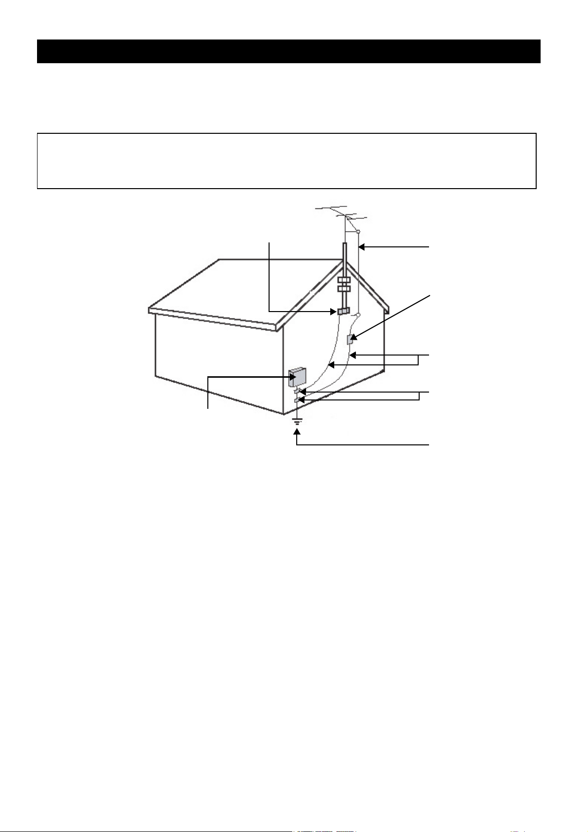
19. Outdoor Antenna Grounding - If an outside antenna is connected to the receiver, be sure the antenna sys-
tem is grounded so as to provide some protection against voltage sure and built up static charges. Section
810 of the National Electric Code, ANSI/NFPA No. 70-1984, provides information with respect to proper
grounding of the mast and supporting structure, grounding of the lead-in wire to an antenna discharge
unit, size of grounding connectors, location of antenna-discharge unit, connection to grounding electrodes,
and requirements for the grounding electrode. See Figure below.
20. Object and Liquid Entry - Care should be taken so that objects do not fall and liquids are not spilled into the
enclosure through openings.
Warning:
moisture and objects filled with liquids, such as vases, should not be placed on this apparatus.
To reduce the risk of fire or electric shock, this apparatus should not be exposed to rain or
English
i
Page 4
Important Safety Instructions
21. Battery Usage CAUTION - To prevent battery leakage that may result in bodily injury, property damage, or
damage to the units:
• Install all batteries correctly, with + and - aligned as marked on the unit.
• Do not mix batteries (old and new or carbon and alkaline, etc.).
• Remove batteries when the unit is not used for a long time.
Note to the CATV system installer: This reminder is provided to call the CATV system installer's attention to
Article 820-40 of the NEC that provides guidelines for proper grounding and, in particular, specifies that the
cable ground shall be connected to the grounding system of the building, as close to the point of cable entry
as practical.
E
LECTRIC SERVICE EQUIPMENT
GROUND CLAMP
ANTENNA LEAD IN WIRE
ANTENNA DISCHARGE UNIT
(NEC
SECTION 810-20)
GROUNDING CONDUCTORS
(NEC
SECTION 810-21)
ROUND CLAMPS
G
POWER SERVICE GROUNDING
ELECTRODE SYSTEM
(NEC
ART. 250, PART H)
ii
Page 5

Table of Contents
Table of Contents
FEATURES. . . . . . . . . . . . . . . . . . . . . 1
Accessories ...................................... 1
INSERTING REMOTE CONTROL BATTERIES . 2
REMOTE CONTROL BUTTONS . . . . . . . . . 3
OVERVIEW OF THE TV . . . . . . . . . . . . . 5
Front Panel ....................................... 5
Front Panel Buttons and LEDs........ 5
Front Panel Connectors................. 7
Rear Panel ........................................ 8
MAKING CONNECTIONS . . . . . . . . . . . 10
Connecting Headphones ................... 10
Connecting Cable TV/Antenna .......... 10
Connecting a VCR ........................... 11
Connecting a PVR............................ 12
Connecting a camera or game console 13
Connecting a Set-Top Box ................ 14
Connecting a DVD Player ................. 15
Connecting a DVD Player ................. 16
Connecting a PC.............................. 17
USING THE OSD MENUS . . . . . . . . . . . 20
Picture Menu .................................. 20
Sound Menu................................... 21
Size Menu ...................................... 22
PIP/PBP Menu................................. 23
Parental Control Menu ..................... 24
Movie Rating............................. 25
TV Rating ................................. 26
Channel Setup Menu ....................... 27
Channel Search ......................... 27
Favorite Channel List.................. 28
Setup Menu.................................... 28
Closed Caption Menu ................. 29
REPLACING THE INTERNAL LAMP. . . . . . . 31
TROUBLESHOOTING . . . . . . . . . . . . . . . 32
SPECIFICATIONS . . . . . . . . . . . . . . . . . 33
MAGNAVOX LIMITED WARRANTY . . 34
English
USING THE TV. . . . . . . . . . . . . . . . . 18
Turning on the TV ........................... 18
Turning off the TV........................... 18
Changing Input Source ..................... 19
Changing Channels .......................... 19
Adjusting Volume ............................ 19
iii
Page 6

Page 7

Features
Features
Congratulations on purchasing the MAGNAVOX 50-inch DLP Projection TV which is
equipped with the latest DLP (Digital Light Processing) and brings razor sharp images and
brilliant colors for your viewing enjoyment.
The MAGNAVOX 50ML8105D/17 has the following useful features:
Immersive entertainment experience
• High definition DLP HD4 technology with 1280 x 720p resolution
• Integrated digital TV tuner to receive and watch high definition broadcast programs
• Progressive scan for razor-sharp and flicker-free images
• 3D comb filter separates colors for a crisp image
Bigger experiences, less space
• Slim, lightweight design with 15.3 inches depth and 114lbs weight.
Advanced connectivity
• Latest HDMI connector, providing superior quality video
• 2x component video (YPbPr) input for high quality video
• D-sub/VGA PC connectivity enables you to use the TV as a PC monitor
One touch convenience
• SmartPicture and SmartSound provide optimized settings
• PIP (Picture In Picture) feature for watching two programs at the same time
Note
English
• Specifications are subject to change without notice.
Accessories
The following items are included with your TV. If any of the items appears to be missing or
damaged, contact your nearest vendor.
•Power cord
• Remote control unit
• AAA battery x 2
• User manual (English / Spanish)
• Quick start guide
• Product Registration Card
1
Page 8
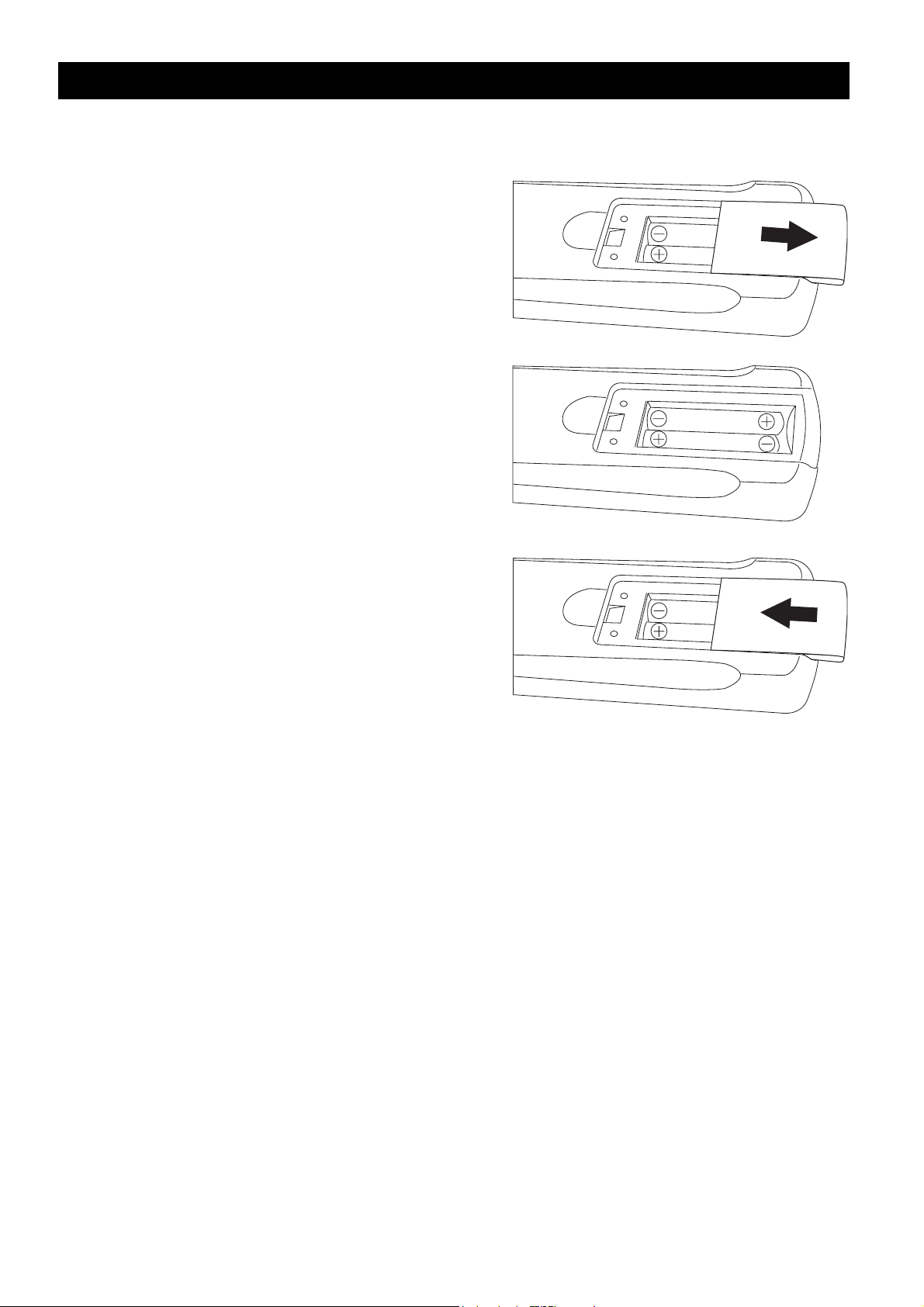
Inserting Remote Control Batteries
Inserting Remote Control Batteries
Use the following procedure to insert batteries into the remote control before you start
using it.
1. The battery cover is on the back of the remote
control. Slide the battery cover in the direction
of the arrow to remove it.
2. Insert the two AAA batteries provided in the
package, with the polarity of the batteries
matching the image in the battery compartment.
3. Slide the battery cover in the direction of the
arrow until it clicks and is secure.
2
Page 9
Remote Control Buttons
Remote Control Buttons
INFO
-
MENU
1
2
3
4
5
6
7
8
9
10
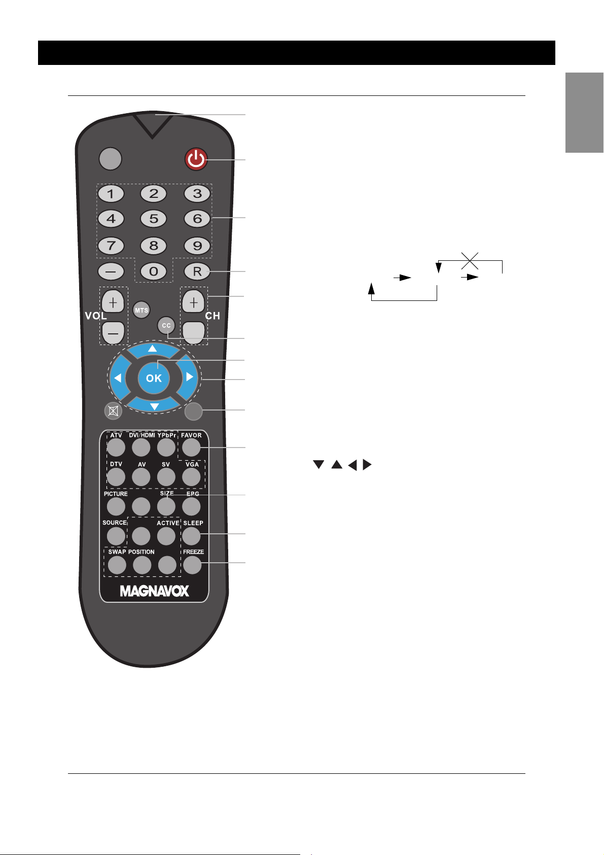
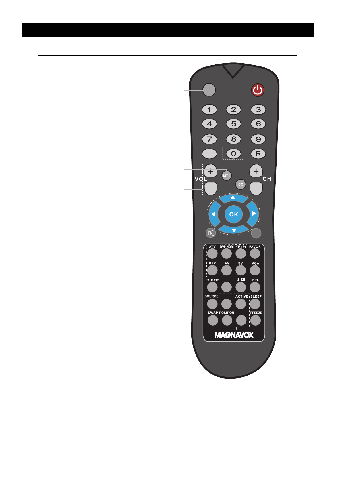
1 IR Filter: Transmits infra-red control signals to
the TV.
2 Power: Press to turn power on/off.
3 Number buttons (0 ~ 9): Press to access a
specific TV channel.
4 R (Recall): Press to switch to the previously
viewed channel.
Note: When this button is pressed, you will
be returned to the previously viewed channel in the same TV mode (analog or digital).
Analog 7 Analog 36 Digital 42
The recall button only returns you to channels of
the same mode.
5 CH (Channel Selection): Press + to
increase the channel number and – to
decrease the channel.
6 CC (Closed Captioning): Press to turn
Closed Captioning off, on, or enable during
mute.
7 OK: Press to activate or confirm menu
choices.
8 Cursor Up, Down, Right, Left
English
SOUND
PIP SIZE
PIP/PBP
11
12
13
14
( ): Press to navigate through
the on-screen menu.
9 MENU: Press to display the TV’s on-screen
menu or to turn it off.
10 FAVOR: Press repeatedly to view the
favorite TV channels. Refer to “Favorite
Channel List” on page 28 for more
information about how to edit the favorite
channel list.
11 SIZE: Press to change the picture aspect
ratio.
12 EPG (Electronic Program Guide): Press to
display the EPG table (if available). Use
arrow keys to navigate through the EPG.
The quality and accuracy of the information
on the program guide and the information
banner are transmitted from the
broadcasters. You may see a difference in
broadcast time if the broadcaster is from a
different time zone.
13 SLEEP: Press to set the sleep timer feature
to turn the TV off automatically.
14 FREEZE: Press to freeze the video image.
3
Page 10
Remote Control Buttons
15 INFO (Information): Press to show
information about the current channel, closed caption availability,
source, size ratio, SmartPicture
SmartSound, and so on.
The quality and accuracy of the
information on the program guide
and the information banner are
transmitted from the broadcasters.
You may see a difference in
broadcast time if the broadcaster is
from a different time zone.
16 Dash key: Press to select additional
digital and analog signals. For example, to select 51-2, press 5, 1,
the dash key and then 2 to view the
channel.
17 MTS (Multi-channel Television
System): Press to toggle through
TV audio modes in NTSC system.
18 VOL (Volume Adjustment): Press
+ to increase volume and – to
reduce the volume.
19 MUTE: Press to disable sound.
Press again to restore sound.
20 Source Shortcut Keys (ATV,
DVI/HDMI, YPbPr, DTV, AV, SV,
VGA): Press to quickly switch be-
tween the various input sources.
21 SOUND: Press to activate the
SmartSound function and cycle
through the SmartSound options.
22 PICTURE: Press to activate the
SmartPicture function and cycle
through the SmartPicture options.
23 SOURCE: Press to select input
source from the on-screen menu.
24 PIP (Picture in Picture) / PBP (Picture
by Picture) Shortcut Keys (refer to
“PIP/PBP Menu” on page 23):
PIP/PBP: Enable or disable PIP or
PBP mode.
POSITION: Press to change the
position of the PIP window.
SWAP: Swap images when using
PIP/PBP.
ACTIVE: Select an active PIP/PBP
window.
PIP SIZE: Press to change the
picture size of the PIP window.
15
16
17
18
19
20
21
22
23
24
INFO
-
MENU
SOUND
PIP SIZE
PIP/PBP
4
Page 11
Overview of the TV
Overview of the TV
The following sections help you to familiarize yourself with the components of your TV.
Refer to this section before you make any connections.
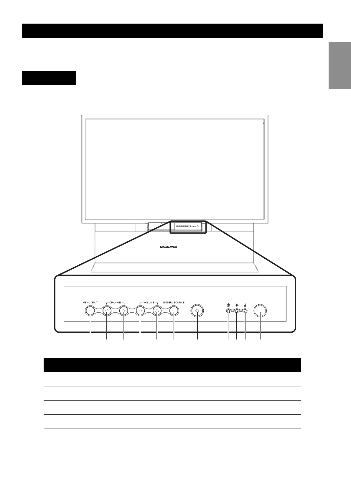
Front Panel
The control panel and indicator LEDs are on the front panel of the TV.
Front Panel Buttons and LEDs
English
1 2 3 4 5 6 7 8910 11
Component Function
1. MENU/EXIT Enable or exit from on-screen display (OSD) menu.
2. CHANNEL DOWN Switch to previous channel.
3. CHANNEL UP Switch to next channel.
4. VOLUME DOWN Decrease volume.
5. VOLUME INCREASE Increase volume.
5
Page 12

Overview of the TV
Component Function
6. ENTER/SOURCE • When OSD menu is enabled, confirm selection of menu
item.
• When OSD menu is disabled, switch sequentially between
all input sources.
7. POWER Turn power on or off.
8. Power indicator • Red: Stand-by
• Flashing red: System being cooled down
• The power indicator status on power on.
• Green: System powered on
• At power off, the LED flashes red/green for 10 seconds,
flashes red for approximately 40 seconds and then turns
red when the system is powered off.
9. Lamp indicator Lamp failed (red)
10. Temperature indica-
tor
11. IR receiver Receive control signals from the remote control
Red: Internal temperature too high
6
Page 13
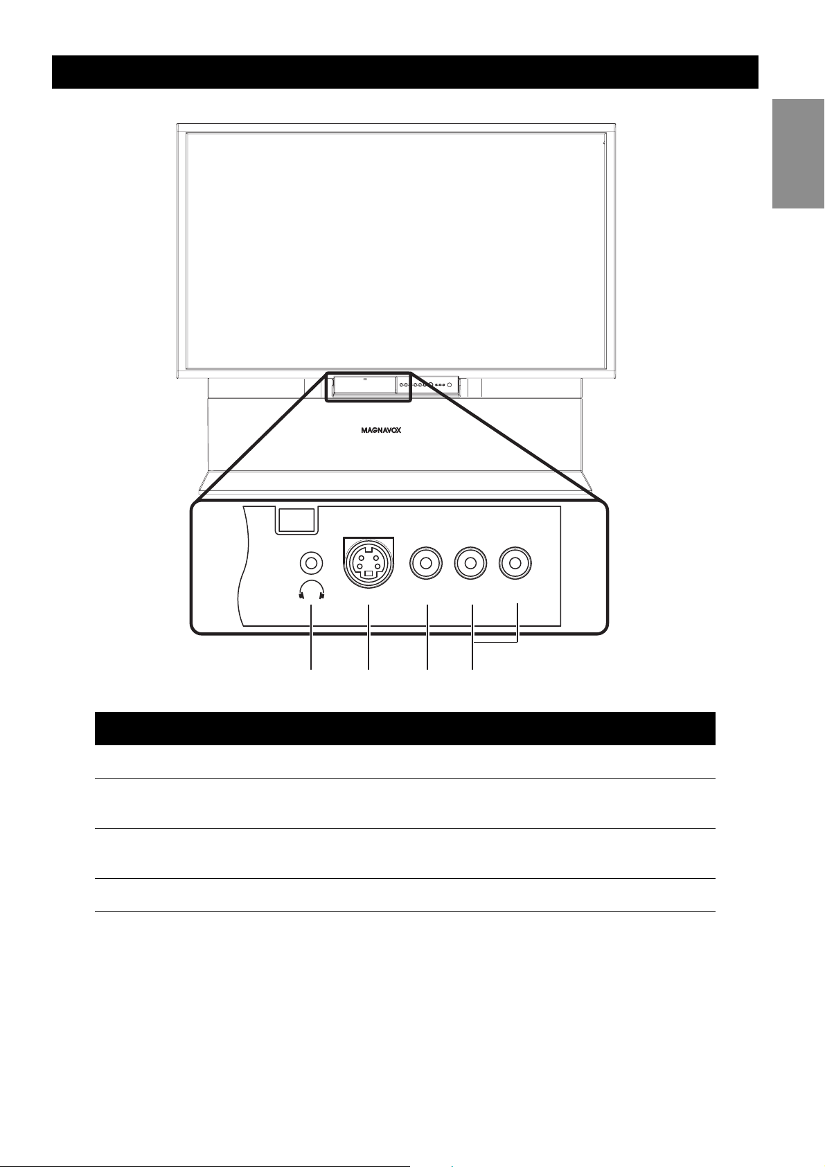
Front Panel Connectors
Overview of the TV
English
S-Video
1 2 3 4
Component Function
1. Headphone Connect headphones to listen to audio.
2. S-Video Connect a device such as a camera, game console, or
DVD player to watch video.
3. Video Connect video device with composite video output
such as a VCR.
4. Audio L/R Connect audio output of device here.
Video
L
R
7
Page 14
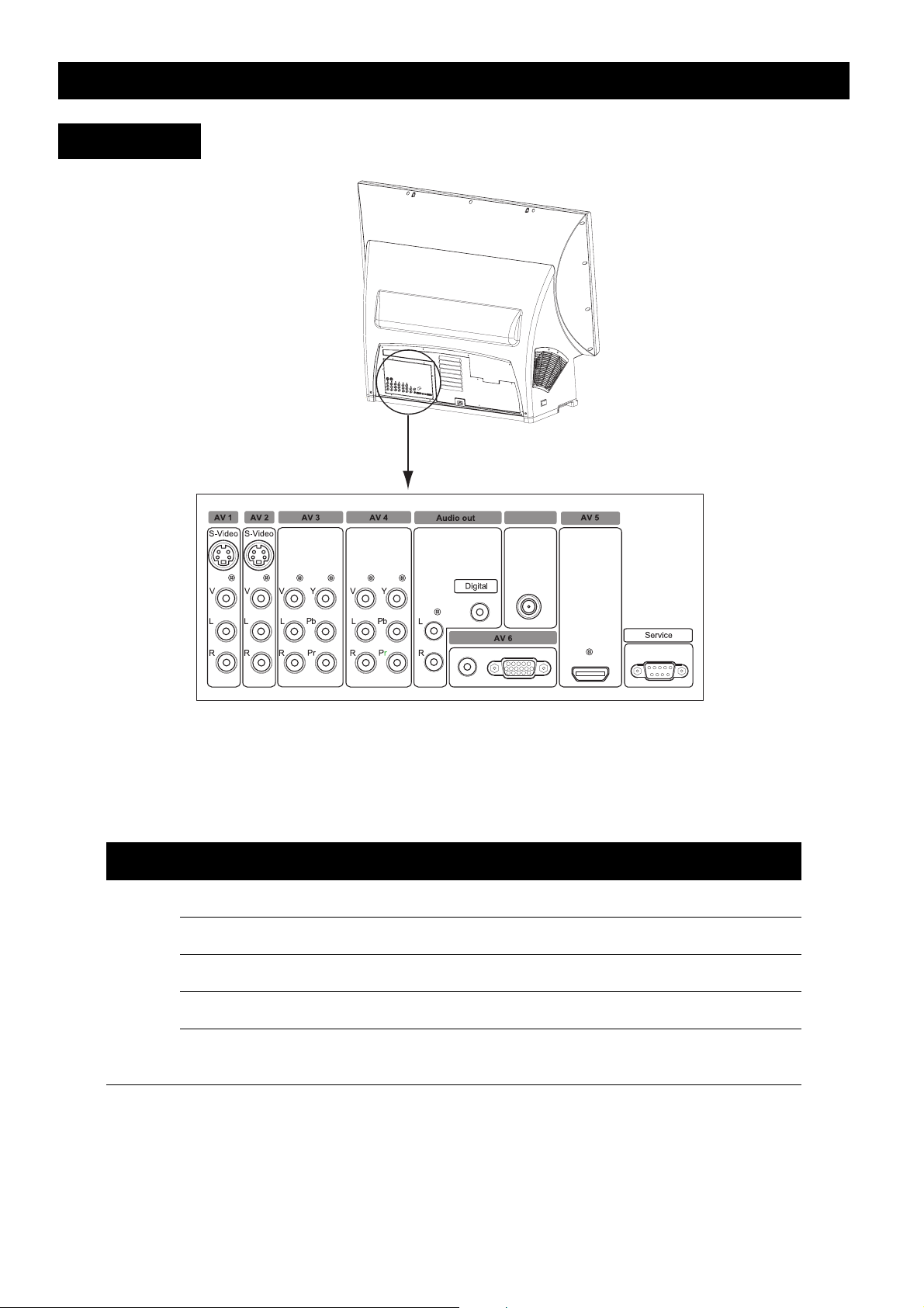
Rear Panel
Overview of the TV
Antenna in
Your TV is designed to accept and display a wide range of video programs and signal
sources, including VCRs, DVD players, high definition (HD) TV devices, video game consoles, and regular TV broadcasts. The TV provides excellent quality picture and audio to
provide a memorable viewing experience. The following table provides a sample of the various devices that can be connected to the connectors of the TV.
Input/Output Example device
Analog AV1 VCR (Video Casette Recorder)
AV2 PVR (Personal Video Recorder)
AV7 (front panel) Game console or camera
Antenna In Antenna
Audio out Audio amplifier system
Digital out and analog L and R out
8
Page 15
Overview of the TV
Input/ Output Example device
Digital AV3 Set-top box
AV4 DVD player or HD game console
AV5 HDMI device
AV6 PC or portable computer with VGA output
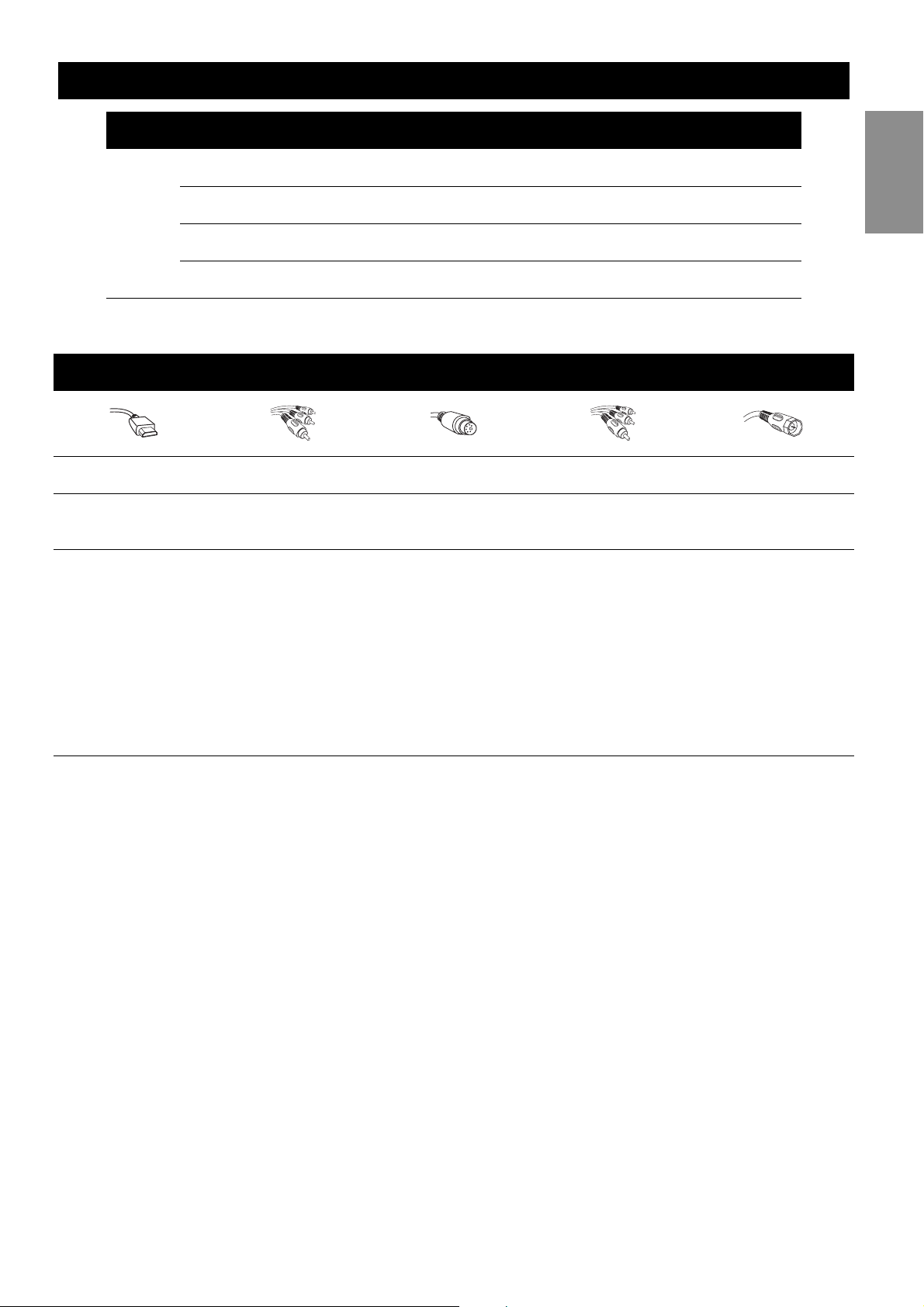
The following table describes the differences between connection types.
CONNECTION BASICS
BEST BETTER GOOD BASIC BASIC
HDMI Component Video S-Video
High-definition Multimedia Interface
provides an uncompressed, all-digital
audio/video connection. HDMI provides
the ultimate connection.
Provides superior picture quality by separating the green,
blue, and red luminance signals. Typically used with
red/white audio
cables.
Supplies a better picture than RF and
Composite connections. Used with
red/white audio
cables.
Composite
Audio/Video
Separate video (yellow) and audio
(red/white) cables
that provide a basic
connection from the
cable box or other
devices.
Note: The color of
audio inputs may differ, e.g. red/white or
red/black.
English
RF
Provides a basic connection for antenna
or cable. Provides
both audio and video.
9
Page 16
Making Connections
Making Connections
The following sections provide instructions on how to connect various audio/video devices
to the TV. Take care to switch off all devices before making any connections.
Most video devices have different types of video connectors. The most common are composite video, component video (YPbPr), and S-video. Component video provides the best
picture quality while S-video delivers medium picture quality. Composite video provides the
lowest picture quality. The following sections provide various examples to illustrate how to
connect different types of devices. Refer to the documentation provided with the device
that you want to use for more information.
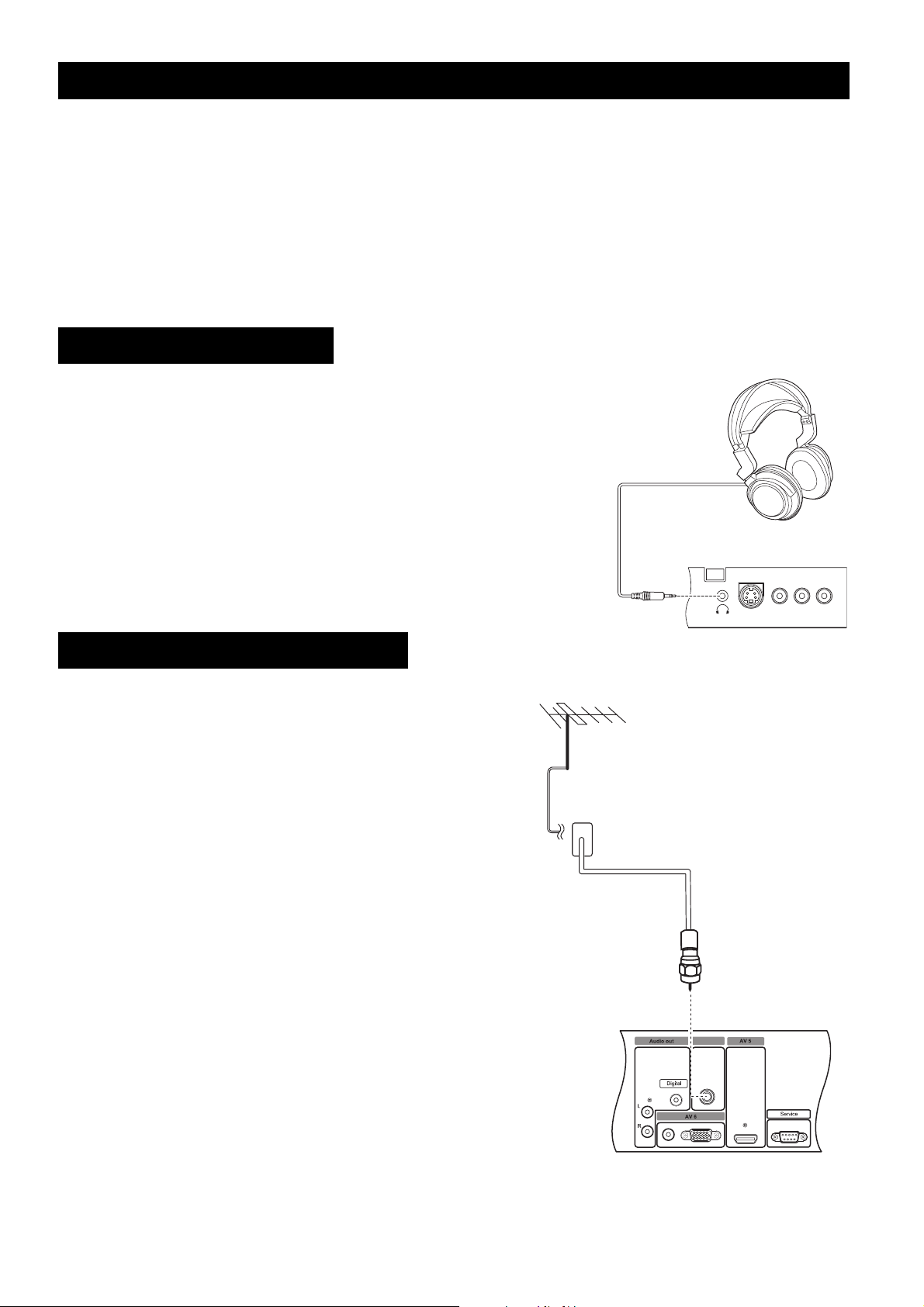
Connecting Headphones
To listen to audio, connect the headphones to the headphone
jack provided on the front panel.
Connecting Cable TV/Antenna
To view High Definition local broadcasts, connect
your outdoor or indoor antenna to the Antenna In
input on the rear panel.
To view Analog Cable, connect your Cable TV to
the Antenna In input on the rear panel.
Antenna in
S-Video
Video
L
R
10
Page 17
Making Connections
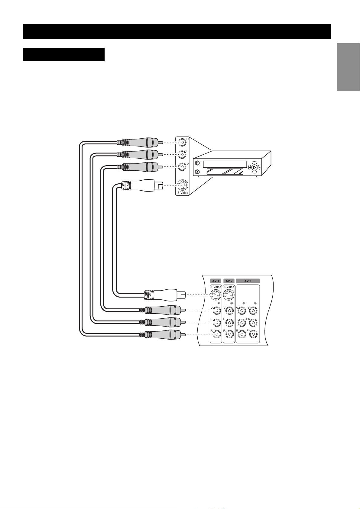
Connecting a VCR
Follow these instructions to connect a VCR (Video Cassette Recorder) to the TV using the
AV1 input and watch your favorite movies.
1. Connect the video output of the VCR to the V connector of the AV1 input using an
RCA cable. Alternatively, you can also connect it to the S-video connector of the AV1
input using an S-video cable.
2. Connect the audio output (L/R) of the VCR to the audio jacks (L/R) of the AV1 input
using RCA cables.
English
11
Page 18
Making Connections
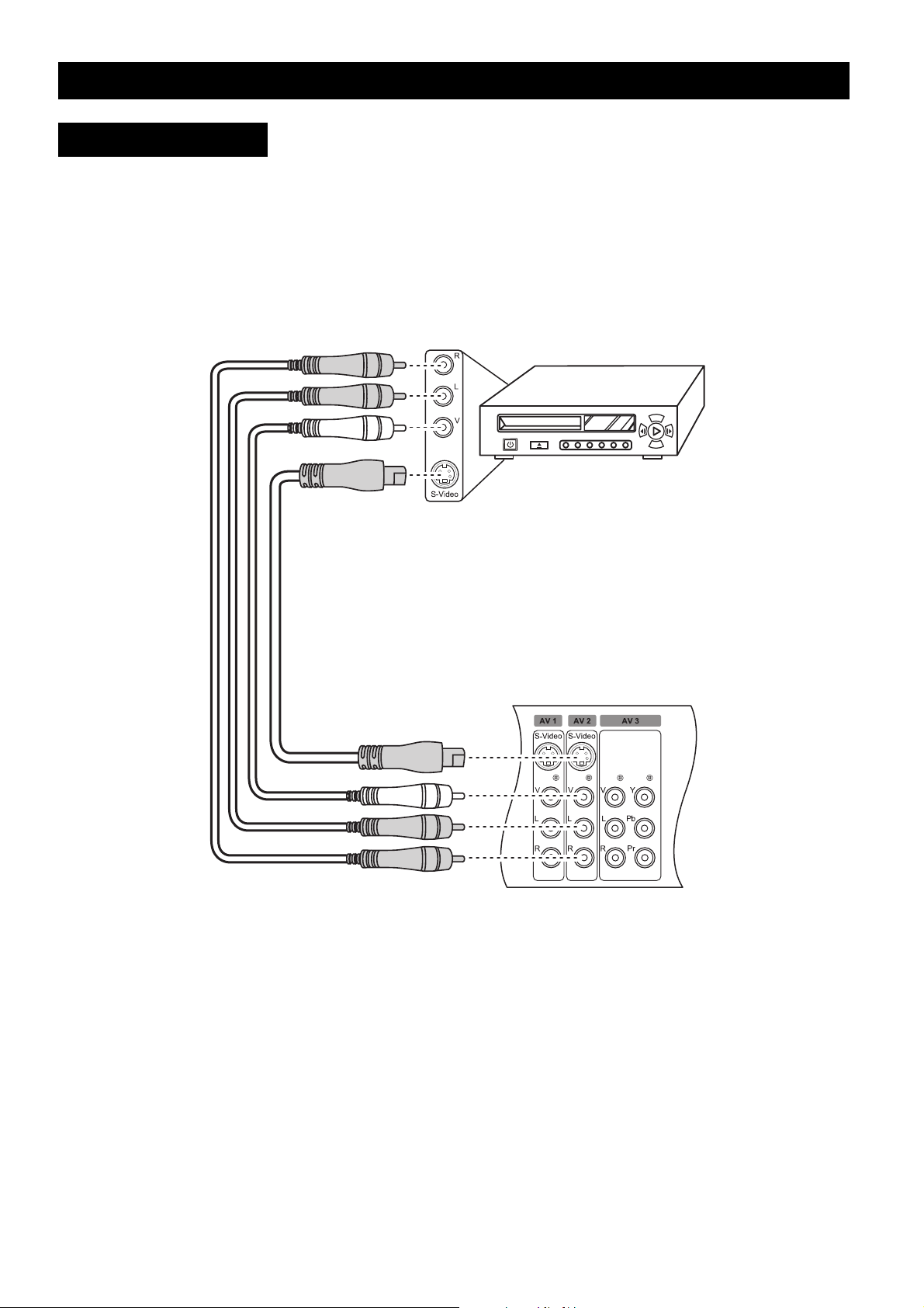
Connecting a PVR
Follow these instructions to connect a PVR (Personal Video Recorder) to the TV using the
AV2 input.
1. Connect the video output of the PVR to the S-video connector of the AV2 input using
an S-video cable. Alternatively, you can also connect it to the V connector of the AV2
input using an RCA cable.
2. Connect the audio output (L/R) of the PVR to the audio jacks (L/R) of the AV2 input
using RCA cables.
12
Page 19
Making Connections
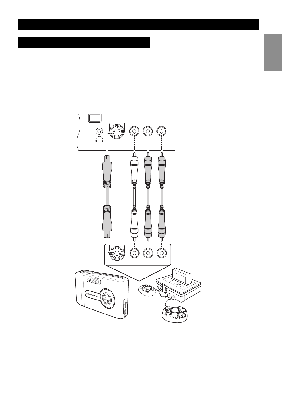
Connecting a camera or game console
To connect a video game console or a camera to the display, you can use the AV connectors located on the front connector panel (AV7). Alternatively, you can also use the AV connectors located on the rear panel.
1. Connect the video output of the camera or game console to the S-video connector on
the front panel using an S-video cable. Alternatively, you can also connect it to the V
connector using an RCA cable.
2. Connect the audio output (L/R) of the camera or game console to the audio jacks (L/R)
using RCA cables.
English
S-Video
S-Video
Video
Video
L
R
LR
13
Page 20
Making Connections
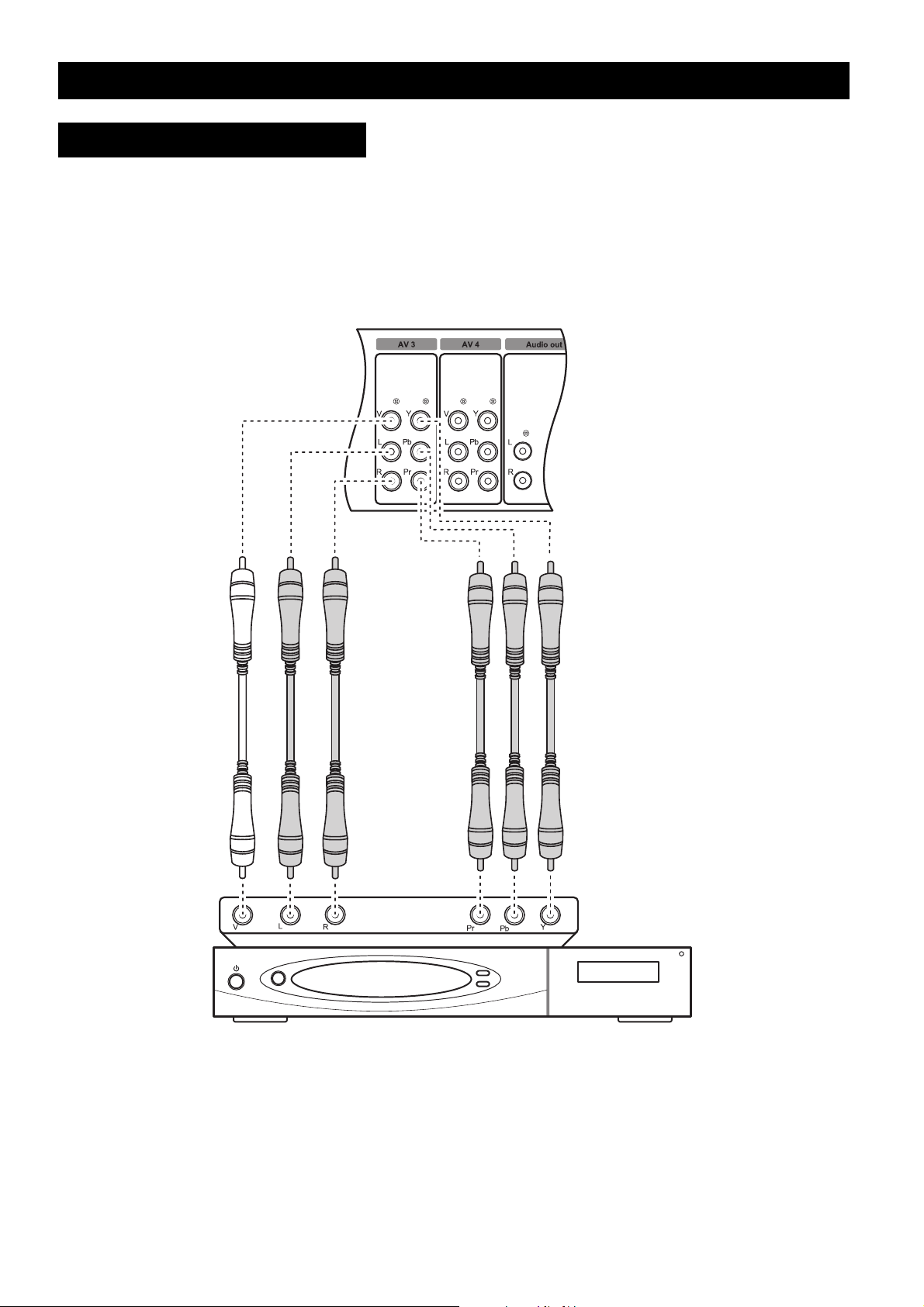
Connecting a Set-Top Box
You can connect a set-top box (cable/satellite) to the TV as follows:
1. Connect the video output of the set-top box to the component (YPbPr) video connec-
tors of the AV3 input using RCA cables. Alternatively, you can also connect it to the V
connector.
2. Connect the audio output (L/R) of the set-top box to the audio jacks (L/R) using RCA
cables.
14
Page 21
Making Connections
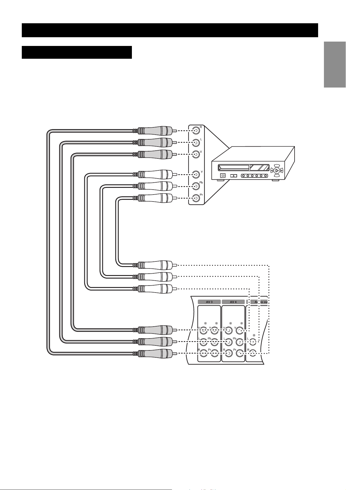
Connecting a DVD Player
To connect a DVD player to the TV, do the following:
1. Connect the video output of the DVD player to the V connector of the AV4 input using
an RCA cable. Alternatively, you can also connect it to the component (YPbPr) connec-
tors.
2. Connect the audio output (L/R) of the DVD player to the audio jacks (L/R) using RCA
cables.
English
15
Page 22
Making Connections
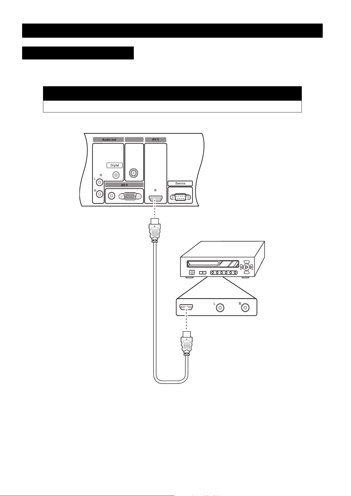
Connecting a DVD Player
To connect a DVD player to the TV using the HDMI input, connect the video output of the
DVD player to the HDMI connector of the AV5 input using an HDMI cable.
Note
• If you are using an DVI-to-HDMI cable, there will be no audio out.
Antenna in
16
Page 23
Making Connections
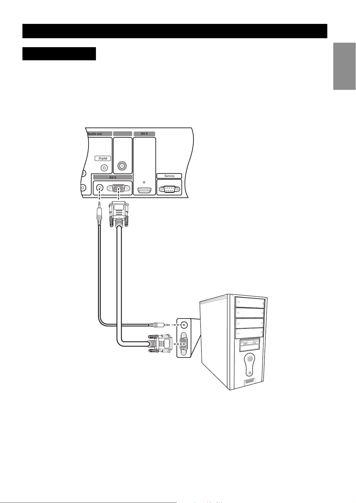
Connecting a PC
Use the following procedure to connect a PC or portable computer to the TV to use it as the
PC’s monitor.
1. Connect the VGA output of the PC to the VGA connector of the AV6 input using a
VGA cable.
2. Connect the audio output (Audio out) of the PC to the audio jack of the AV6 input
using an audio cable.
Antenna in
English
17
Page 24
Using the TV
Using the TV
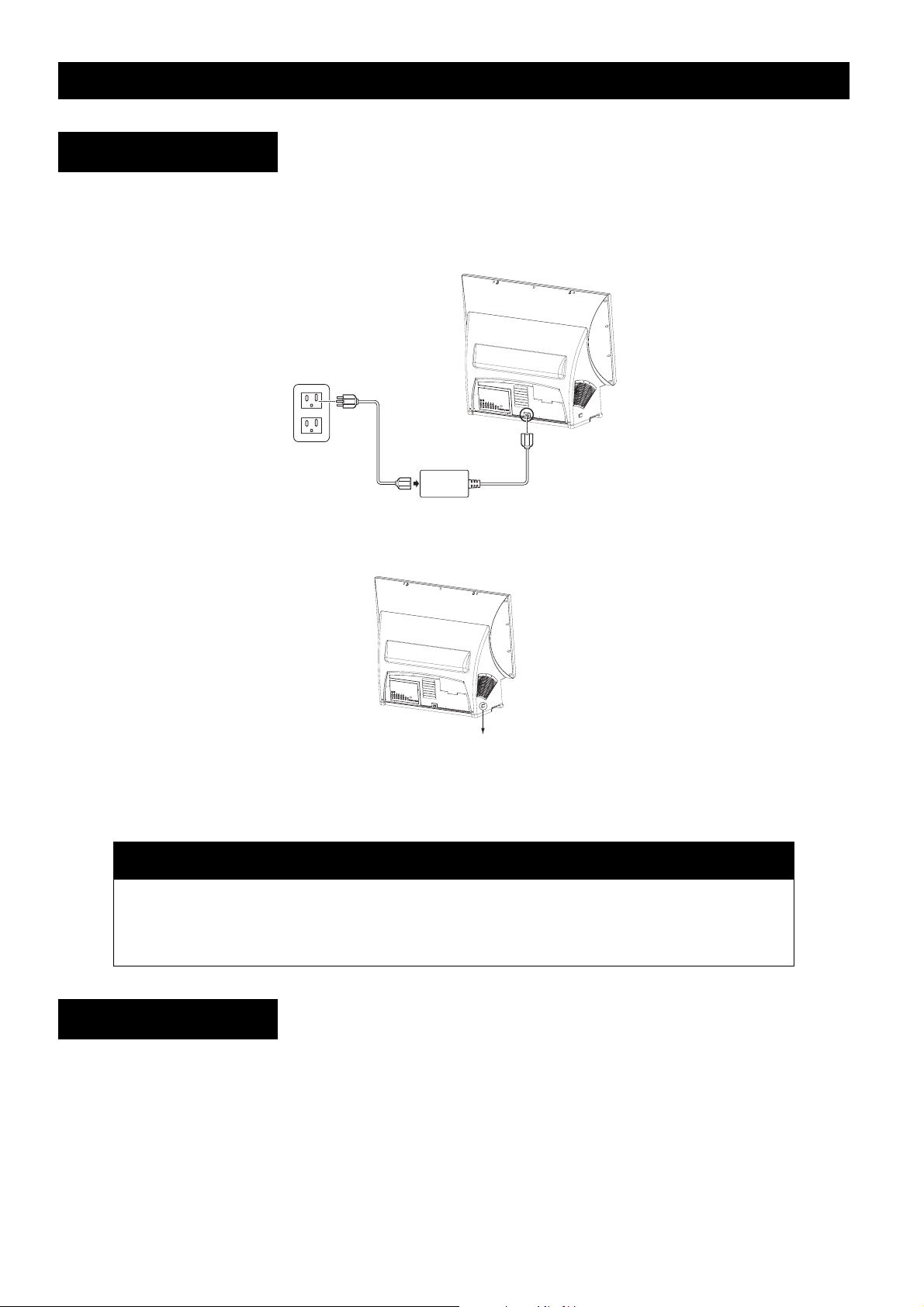
Turning on the TV
To switch on the TV, do the following:
1. Connect the power cord to the TV as illustrated and plug the cord into a free wall out-
let.
2. Switch on the main power switch. Refer to the following illustration for the location of
the main power switch.
Power switch
3. Press the power button on the front panel or remote control to turn on the TV. The TV
will turn on after warming up in approximately 30 seconds.
Notes
• If the remote control and control panel do not work, ensure that the power switch on the
rear of the TV is set to ON.
• In extremely quiet surroundings, you may hear a slight hum, which comes from the cooling system of the set and is part of its normal operation.
Turning off the TV
To switch the TV off, press the power button on the front panel or remote control to turn
off the TV. The screen turns blank immediately but it will take approximately 1 minute to
cool down and then shut down the whole system.
Except in case of emergency, it is not recommended to use the main power switch to
switch off the system. The lamp life may be severely reduced if the system is not allowed
to cool down properly by abruptly shutting down the system using the main power switch.
18
Page 25

Notes
Using the TV
• Unless the TV is not going to be used for an extended period of time, the main power
switch can be left in the ON position without consuming a lot of power.
• After you switch off the TV, the power LED flashes red/green for 10 seconds, flashes red
for approximately 40 seconds and then turns red when the system is powered off. When
the LED is flashing red, the TV is in its final cooling phase and the system will not respond
to any commands from the remote control or front panel buttons. Wait until the power
LED stops flashing for about 1 minute before switching on the TV again.
Changing Input Source
After switching on the TV, select the appropriate input source using the front panel buttons
or the remote control as follows:
•Press ATV, DVI/HDMI, YPbPr, DTV, AV, SV, or VGA on the remote control to switch to
the respective input.
•Press the ENTER/SOURCE button on the front panel of the TV repeatedly to switch
through all the input sources.
•Press SOURCE on the remote control to select the source
from the on-screen menu. A list of input sources is displayed
on the screen. Select the appropriate input using the cursor
keys and press OK on the remote control to display the input
signal.
Input Select
EXIT
ATSC
Analog TV
AV1
AV2
AV3
AV4
HDMI
VGA
Front
English
Changing Channels
Use one of the following methods to change channels:
• Press the channel up or down buttons on the front panel or the remote control to switch
to the previous or next channel.
• Press the number keys on the remote control to directly key in a channel number.
Adjusting Volume
To adjust volume, do the following:
• Press the volume up or down buttons on the front panel or the remote control to
increase or decrease the volume.
• Press the mute button (see page 4) to disable the volume. Press the button again to
restore sound.
19
Page 26

Using the OSD menus
Using the OSD menus
The On-Screen Display (OSD) menus enable you to customize the TV’s audio, video, and
other settings according to your preferences. Press the MENU button on the front panel or
the remote control to view the OSD menu. Use the buttons to navigate through
the menu items and press OK to select an option. Press the MENU button again to exit from
the menu. Refer to the following sections to learn more about the various menu options.
Picture Menu
The picture menu enables you to
adjust the picture to suit the type of
program you are watching. The
SmartPicture item provides four
preset options for the picture setting – Personal, Dynamic, Natural,
and Cinema. You can also choose
to manually adjust the picture settings such as brightness, contrast,
saturation, etc. to suit your personal preference.
Main Menu
Picture
Sound
Size
PIP/PBP
Parental Control
Channel Setup
Setup
Exit
SmartPicture
Brightness
Contrast
Sharpness
Temp.
Tint
Saturation
Back
Personal
Dynamic Natural Cinema
Warm Normal Cool
50
50
7
50
50
The following table describes the picture menu items.
Component Function Range / Options
SmartPicture Provides four preset options to suit various
types of programs.
Brightness Adjusts the total brightness of all colors. 0 ~ 100
Contrast Modifies the ratio between extremely dark
and extremely light areas of the image.
Sharpness Modifies the sharpness of the edges of the
image.
Temp. Adjusts the color temperature or warmth of
the image. An image with warm colors has
more reddish hues.
Tint Modifies the hue or dominant color of the
image.
Saturation Adjusts the color intensity of the image. 0 ~ 100
Personal, Dynamic, Natural,
Cinema
0 ~ 100
0 ~ 15
Warm, Normal, Cool
0 ~ 100
20
Page 27

Using the OSD menus
Sound Menu
The sound menu helps you to
adjust the audio settings to suit the
type of program being viewed. The
SmartSound item provides four preset options for the audio quality –
Personal, Music, Cinema, and
Voice. You can also adjust the
audio settings manually as required.
The following table describes the
sound menu items.
Component Function Range / Options
Main Menu
Picture
Sound
Size
PIP/PBP
Parental Control
Channel Setup
Setup
Exit
SmartSound
Treble
Bass
MTS
Mute
Balance
Back
Personal
Music Cinema Vo ice
50
50
Mono Stereo SAP
Off
On
LR
50
English
SmartSound Provides four preset options to suit various
Personal, Music, Cinema, Voice
types of programs.
Treble Adjusts amount of high-frequency compo-
0 ~ 100
nents in the audio.
Bass Adjusts amount of low-frequency compo-
0 ~ 100
nents in the audio.
MTS
Sets the audio mode.
†
Mono, Stereo, SAP (Secondary
Audio Program)
Mute Disables audio. Off, On
Balance Adjusts the sound balance between the left
0 ~ 100
and right speakers.
† MTS is only available when the input signal is analog.
21
Page 28

Using the OSD menus
Size Menu
The size menu provides various
options for the size or aspect ratio
of the video display.
The following options are available:
Component Function
Main Menu
Picture
Sound
Size
PIP/PBP
Parental Control
Channel Setup
Setup
Exit
Normal
Super zoom
4:3
Movie expand 14:9
Movie expand 16:9
Subtitle zoom
Wide screen
Back
Normal The picture is enlarged to cover the entire screen area.
Super zoom In Super zoom mode, the picture is expanded nonlinearly in the hori-
zontal direction, and compressed nonlinearly in the vertical direction.
4:3 This format resizes the picture size to 960 x 720 pixels. Unused por-
tions of the screen are left black.
Movie expand 14:9 Expand the picture to remove the black bars.
Movie expand 16:9 Expand the picture to remove the black bars.
Subtitle zoom Zooms across the subtitle area.
Wide screen This format is used to view feature films, with an aspect ratio of 1.77 : 1.
22
Page 29

Using the OSD menus
PIP/PBP Menu
The PIP/PBP menu provides various
options for the PIP and PBP modes.
The PIP mode helps you to watch
one program on the full screen, and
another program on a smaller
pop-up window, which can be positioned in any of the four corners of
the screen. The PBP function
divides the viewing area into two
halves, allowing the simultaneous
viewing of two programs in windows placed side by side. Refer to
the following table to learn about the various menu items:
Component Function Range / Options
Mode Enables single, PIP, or PBP mode. Single, PIP, PBP
Main Menu
Picture
Sound
Size
PIP/PBP
Parental Control
Channel Setup
Setup
Exit
Mode
PIP Position
PIP Size
Sound Source
Back
Single PBPPIP
Small Medium
Main Sub
English
Large
PIP Position Sets the position of the PIP window in one of
the four corners of the screen.
Top left, Top right, Bottom right,
Bottom left
PIP Size Selects the size of the PIP window Small, Medium, Large
Sound Source Selects the sound source to be outputted
Main, Sub
through the speakers.
Refer to the following tables for PIP/PBP combinations:
Main Sub window
Component S-Video
VGA Composite
DTV ATV
HDMI
Sub window Main
Component S-Video
VGA Composite
DTV ATV
HDMI
For instance, if the main window displays the Component input signal, you can select the
S-video, Composite, or ATV inputs as the sub window.Similarly, if the main signal is the
Composite input, the sub window can display the Component, VGA, DTV, or HDMI inputs.
Notes
• You can also use the PIP/PBP, PIP SIZE, ACTIVE, SWAP, and POSITION buttons on the
remote control to activate and control the PIP or PBP mode. See page 4.
• Use the SWAP button to switch programs between the main and secondary windows in
PIP/PBP mode.
23
Page 30

Using the OSD menus
Parental Control Menu
The parental control menu enables
you to limit access to programs that
may contain objectionable material
or are not suitable for viewing by
children. The default access code is
0711.
The following table provides details
about the menu items:
Component Function Range / Options
Main Menu
Picture
Sound
Size
PIP/PBP
Parental Control
Channel Setup
Setup
Exit
Lock Enable
Movie Rating
TV Rating
Change Code
Reset
Back
Off On
Press Right to Enter
Press Right to Enter
Press New Code
Press Right to Enter
Lock Enable Enables the parental control lock. When
enabled, channels with objectionable viewing
content are blocked and can only be
accessed with a password. You can block
channels according to the movie or TV ratings of the channel’s programs.
Movie Rating Helps you block programs based on their
movie ratings. See “Movie Rating” on
page 25 for more details.
TV Rating Helps you block programs based on their TV
ratings. See “TV Rating” on page 26.
Change Code Changes the password for the parental con-
trol lock.
Reset Resets all channels and programs to their
default factory settings.
Off, On
–
–
Press the number keys to
change the password.
–
24
Page 31

Using the OSD menus
Movie Rating
The movie rating provides a list of
all the movie (MPAA) ratings. The
locked ratings are indicated by the
icon. Press the arrow keys to
select and the OK key to activate or
de-activate the appropriate movie
ratings. For instance, if you want to
view programs that have only G,
PG, and PG-13 ratings, activate the
parental lock for all other movie ratings. The following table provides
more information about the movie
ratings.
Movie Rating Suitable for
G General audience. No restriction.
PG Parental guidance.
Main Menu
Movie Rating
English
G PG PG-13 R NC-17 X NR
Back
PG-13 Children under 13 should be accompanied by
an adult.
R Restricted. Viewers should be 17 or older.
NC-17 Not classified. Viewers should be 17 or older.
X Adults only.
NR Not rated.
25
Page 32

Using the OSD menus
TV Rating
The movie rating provides a list of
all the TV (FCC) ratings. The locked
ratings are indicated by the icon.
Press the arrow keys to select and
the OK key to activate or de-activate the appropriate TV ratings.
For instance, if you want to view
programs that have only TV-Y,
TV-Y7, and TV-G ratings, activate
the parental lock for all other TV
ratings. You can also block the program according to the TV (FCC)
content. The following tables provides more information about the TV ratings and TV content categories.
Main Menu
TV Rating
Back
TV-Y TV-Y7 TV-G TV-PG TV-14 TV-MA Unrated
All
FV
V
S
L
D
TV Rating Suitable for
TV-Y Young children
TV-Y7 Children of age 7 and over
TV-G General audience
TV-PG Parental guidance
TV-14 Viewers of age 14 and over
TV-MA Mature audience
Unrated Not rated.
TV (FCC) Content
Category
V Violence
S Sexual content
L Offensive language
D Dialog with sexual innu-
FV Fantasy or cartoon vio-
Content
endo
lence
26
Page 33

Using the OSD menus
Channel Setup Menu
The channel setup menu helps you
to configure and set up channels.You can set the tuner for signals from the antenna or a cable
receiver, search for channels, and
edit the favorite channels
.
Component Function Range / Options
Main Menu
Picture
Sound
Size
PIP/PBP
Parental Control
Channel Setup
Setup
Exit
Tuner Mode
Channel Search
Manual Search 30
Favorite Channel
Reset Channel
Back
Antenna Cable
English
Press right
Press rightEdit
Tuner Mode Specifies antenna or cable input for the
Antenna, Cable
Analog signal.
Specifies antenna input for the Digital signal.
Channel Search Scans for channels automatically. See
–
“Channel Search” below.
Manual Search Enables you to manually search for chan-
†
nels.
Favorite Channel Edits the favorite channel list. See “Favorite
2 ~ 69
–
Channel List” on page 28.
Reset Channel Clears all channels that were added to the
–
channel list using the Channel Search feature. After using this function, use Channel
Search to rescan for channels.
†
† This selection is only available when the input signal is digital.
Channel Search
Use this option to start scanning for channels automatically as follows:
1. Select the Channel Search item
from the channel setup menu
Auto Scanning
and press to start scanning
for channels automatically.
Scanning begins.
2. Press OK at any time to stop
Antenna
RF Channel: 11
Major Number: 2
scanning.
Auto Scanning
Cable
RF Channel: 11
RF Channel: 11
Digital signal auto scan OSD
27
Analog signal auto scan OSD
Page 34

Using the OSD menus
Favorite Channel List
You can set any channel as your favorite channel and view it quickly using the Favor button
on the remote control. To set up your favorite channels, do the following:
1. Select the Favorite Channel item from the chan-
nel setup menu and press to edit the favorite
channel list.
2. Press Channel +/– to select a channel.
3. Use the / arrow keys to select Add to add the channel to the favorite channel list
or Remove to remove a channel from the list.
4. Press OK to confirm your selection.
Setup Menu
The setup menu provides various
options to customize the TV’s settings.
Main Menu
Picture
Sound
Size
PIP/PBP
Parental Control
Channel Setup
Setup
Exit
OSD Hold Time
Language
Sleep Timer
Closed Caption
Time Zone
Daylight Saving
Back
Favorite Channel Edit
Ch 10 Add Remove
Press Ok to Exit
5s
10s 20s 25s 30s15s
English
Español Français
Off
15m 30m 60m 90m
Press Right to Enter
Atlantic Eastern Central
Pacific Alaska Hawaii
Off On
Mountain
The following table describes the
menu items:
Component Function Range / Options
OSD Hold Time Sets the idle time for which the OSD menu is
displayed on the screen.
Language Sets the OSD menu language. English, Spanish, French
Sleep Timer Sets the time after which the display is
switched off and enters standby mode.
Closed Caption Displays the closed caption menu. Refer to
the following section for details.
Time Zone
Sets the time zone you are in.
Daylight Saving Enables and disables daylight saving. When
set to On, one hour is added to the time.
†
†
† This selection is only available when the input signal is digital.
5s, 10s, 15s, 20s, 25s, 30s
Off, 15m, 30m, 60m, 90m
–
Atlantic, Eastern, Central,
Mountain, Pacific, Alaska,
Hawaii
On, Off
28
Page 35

Using the OSD menus
Closed Caption Menu
The closed caption menu enables you to customize the closed captions according to your
preference. Plain text messages can be viewed while viewing analog RF signals. Digital captions that can be customized for color, font size, opacity and other parameters are available
with digital broadcast signals.
Main Menu
Closed Caption
Enable
Caption Mode
Back
Off
On
CC1 CC2 CC3 CC4 TXT1 TXT2 TXT3 TXT4
Closed caption menu (analog)
English
Main Menu
Closed Caption
Enable
Caption Mode
Display Type
Font Type
Font Size
Pen Type
Off
On
CC1 CC2 CC3 CC4 TXT1 TXT2 TXT3 TXT4
Service 1
Service 2 Service 3 Service 4 Service 5 Service 6
Author define User define
Default Serifmono Serif Sanserifmono Sanserif Casual
Cursive SmallCaptial
Normal
Small Large
Italic Underline
Normal
Main Menu
Closed Caption
Text Color
Text Opacity
Background Color
Background Opacity
Edge Type
Edge Color
Back
Black White Red Green Blue Yellow Magneta Cyan
Solid Transparent Translucent Flashing
Black White Red Green Blue Yellow Magneta Cyan
Solid Transparent Translucent Flashing
None Raised Depressed Uniform Dropshadow
Black White Red Green Blue Yellow Magneta Cyan
Closed caption menu (digital)
The following table provides a description of the closed caption menu options in digital
mode:
Component Function Range / Options
Enable Enables closed captioning. On, Off
Caption Mode Selects a closed caption or service mode. CC1 ~ CC4, TXT1 ~ TXT4,
Service 1 ~ Service 6
Display Type When User define is selected, the user can
set the closed caption menu characteristics
shown below Display Type. If Author define
is selected, these items are unavailable.
Author define, User define
Font Type Specifies a font. Default, Serifmono, Serif, Sanserif-
mono, Sanserif, Casual, Cursive,
SmallCapital
Font Size Specifies the font size. Normal, Small, Large
Pen Type Selects a pen type. Normal, Italic, Underline
29
Page 36

Using the OSD menus
Component Function Range / Options
Text Color Selects text color. Black, White, Red, Green, Blue, Yel-
low, Magenta, Cyan
Text Opacity Sets the opacity of the text. Solid, Transparent, Translucent,
Flashing
Background Color Specifies a background color. Black, White, Red, Green, Blue, Yel-
low, Magenta, Cyan
Background
Opacity
Edge Type Sets the font edge type. None, Raised, Depressed, Uniform,
Edge Color Sets the font edge color. Black, White, Red, Green, Blue, Yel-
Sets the background opacity Solid, Transparent, Translucent,
Flashing
Dropshadow
low, Magenta, Cyan
30
Page 37

Replacing the Internal Lamp
Replacing the Internal Lamp
To order a replacement lamp, call the Magnavox Customer Care Center at 1-800-705-2000. A Magnavox
associate will be happy to assist you.
The part number for the Magnavox replacement lamp is SP.L6502G001
Warning!
• Turn off the unit and unplug it before replacing the lamp
• Take care that no screws or other foreign metal objects fall into the display interior. Such items
could cause fire or electrical shock.
• Do not remove the lamp except to replace it. Careless handling can cause injury or fire.
• Do not replace the lamp immediately after the display is turned off. The high temperature of the
lamp could cause serious burns. Allow the lamp to cool down at least two hours after turning
off the display
1. Remove the front decorative cover. 2. Unscrew and remove the protective cover from
the lamp module.
English
3. Loosen the three screws on the lamp unit and
pull the lamp module out.
Note: These screws can be loosened but cannot be
removed from the unit.
5. Replace the protective cover and tighten the
screws.
4. Replace a new lamp module then screw back the
three screws on the lamp unit.
6. Replace the front decorative cover.
31
Page 38

Troubleshooting
Troubleshooting
Problem Item to check
No power • Check that the power cord is properly connected.
• Make sure the wall power outlet is working.
• Make sure the remote has batteries.
• If the remote control and control panel do not work, ensure that the
power switch on the rear of the TV is set to ON.
Remote control not working • Replace the batteries
• Check that the batteries are inserted correctly
• Check that the remote control is close enough to the display
• Adjust the angle between the remote control and the display.
Picture is fuzzy • Check that the device generating the picture signal is operating prop-
erly.
• Check that you have set the display to receive the proper signal source.
No sound • Check to see if the Mute function is activated.
• Check the volume level.
• Check that the device generating the audio signal is properly connected
to the display.
Picture is unstable • Check that your video card is set within the allowable range.
Screen is blank • Contact the dealer where you purchased the display.
A buzzing sound comes from
the speakers during display.
No image. • Check that the signal source is connected to the correct terminal.
Temperature LED is red • Turn off the TV set and allow it to cool down. If the LED still persists,
Poor picture quality • Try switching to another channel and see if the problem persists.
Picture rolls vertically • Adjust the antenna.
Lamp indicator LED red • Lamp failed. Contact your nearest service center.
There is a switch on the TV • Default is on.
Other • Contact the dealer, authorized service personnel, or the Magnavox help
• Check that the socket of the grounded hole is good.
contact the nearest service center.
• Adjust the antenna.
• Check all cable connections.
• Check all cable connections.
• If you are using a VCR, check the tracking.
number provided here: 1-800-705-2000
32
Page 39

Specifications
Specifications
Picture/Display
• Aspect ratio: wide screen 16:9
• Diagonal screen size: 50-inch
• Display technology: Digital Light Processing DLP™
HD4 with Smooth Picture
• Contrast ratio: 1500 :1
• Picture enhancement: Progressive scan, 3D comb
filter, 3:2 pull down film-mode detection,
SmartPicture
• Viewing angle (vertical): 120 degree
• Viewing angle (horizontal): 160 degree
Connectivity
• Input 1: S-video & composite video + L/R audio
• Input 2: S-video & composite video + L/R audio
• Input 3: YPbPr & composite video + L/R audio
• Input 4: YPbPr & composite video + L/R audio
• Input 5: HDMI
• Input 6: PC/VGA (D-Sub 15pin + audio)
• Input 7 (front): S-video & composite video + L/R
audio
• Output (front): earphones
• RF input: ATSC/NTSC combo tuner
• SPDIF coaxial digital audio output (ATSC only)
• Analog audio output (L/R)
Convenience
• Local controls: front panel keypad
• Ultra long lamp life: > 10,000 hours
• User manual in 2 languages: English (US) and
Spanish
• OSD menu in 3 languages: English (US), Spanish,
and French
• Picture In Picture (PIP)
• Ease of use: SmartSound control, SmartPicture
control
• Ease of installation: PLL digital tuning
• Child protection: Parental control, child lock
• Remote control type: RC-47SLO (RC-6)
Sound
• Output power (RMS): 2 x 15W
• Sound enhancement: SmartSound
English
Tuner reception/transmission
• TV system: NTSC, ATSC
• Aerial input: 75 Ohm F-type
• Video playback: NTSC
• Closed Caption function
Supported Display Resolution
• Computer formats:
– 640 x 480 60Hz
– 800 x 600 60Hz
– 1024 x 768 60Hz
– 1280 x 768 60Hz
• Video formats:
– 720p 60Hz
– 1080i 60Hz
– 480p 60Hz
–480i 60Hz
Power
• Hot re-strike time: < 45s
• Power consumption: < 300W
• Standby power consumption: < 3W
• Power off power consumption: < 1W
• Mains power: AC 100-240V, 50-60Hz
Dimensions
• Product dimensions (WxDxH): 46.7in x 15.3in x
36.in
• Product weight: 114 lbs
33
Page 40

MAGNAVOX LIMITED WARRANTY
MAGNAVOX LIMITED WARRANTY
One (1) Year Labor & One (1) Year Parts & One (1) Year Display Repair
MAGNAVOX warrants this product against defect in material or
workmanship, subject to any conditions set forth as follows:
PROOF OF PURCHASE:
You must have proof of the date of purchase to receive warranted repair on the product. A sales receipt or other document
showing the product and the date that you purchased the product as well as the authorized retailer included, is considered
such proof.
COVERAGE:
(If this product is determined to be defective)
LABOR: For a period of one (1) year from the date of purchase,
Magnavox will repair or replace the product, at its option, at no
charge, or pay the labor charges to any Magnavox authorized
service center. After the period of one (1) year, Magnavox will
no longer be responsible for charges incurred.
PARTS: For a period of one (1) year from the date of purchase,
Magnavox will supply, at no charge, new or rebuilt replacement
parts in exchange for defective parts. Magnavox authorized
service centers will provide removal and installation of the
parts for one (1) year.
DISPLAY: For a period of one (1) year from the date of purchase, Magnavox will supply, at no charge, a new or rebuilt
active display device in exchange for the defective display.
Magnavox authorized service centers will provide removal and
installation of the parts under the specified labor warranty.
(PTV screens carry a thirty (30) day replacement warranty.)
EXCLUDED FROM WARRANTY COVERAGE
Your warranty does not cover:
• Labor charges for installation or setup of the product,
adjustment of customer controls on the product, and installation or repair of antenna systems outside of the product.
• Product repair and/or part replacement because of
improper installation, connections to improper voltage supply, abuse, neglect, misuse, accident, unauthorized repair
or other cause not within the control of Magnavox.
• A product that requires modification or adaptation to
enable it to operate in any country other than the country
for which it was designed, manufactured, approved and/or
authorized, or repair of products damaged by these modifications.
• Damage occurring to product during shipping when
improperly packaged or cost associated with packaging.
• Product lost in shipment and no signature verification of
receipt can be provided.
• A product used for commercial or institutional purposes
(including but not limited to rental purposes).
• Products sold AS IS or RENEWED.
TO OBTAIN WARRANTY SERVICE IN THE U.S.A., PUERTO
RICO, OR U.S. VIRGIN ISLANDS…
Contact Magnavox Customer Care Center at:
1-800-705-2000
TO OBTAIN WARRANTY SERVICE IN CANADA…
1-800-661-6162 (French Speaking)
1-800-705-2000 (English or Spanish Speaking)
REPAIR OR REPLACEMENT AS PROVIDED UNDER THIS
WARRANTY IS THE EXCLUSIVE REMEDY FOR THE CONSUMER. MAGNAVOX SHALL NOT BE LIABLE FOR ANY
INCIDENTAL OR CONSEQUENTIAL DAMAGES FOR
BREACH OF ANY EXPRESS OR IMPLIED WARRANTY ON
THIS PRODUCT. EXCEPT TO THE EXTENT PROHIBITED
BY APPLICABLE LAW, ANY IMPLIED WARRANTY OF MERCHANTABILITY OR FITNESS FOR A PARTICULAR PURPOSE ON THIS PRODUCT IS LIMITED IN DURATION TO
THE DURATION OF THIS WARRANTY.
Some states do not allow the exclusions or limitation of incidental or consequential damages, or allow limitations on how
long an implied warranty lasts, so the above limitations or
exclusions may not apply to you. In addition, if you enter into a
service contract agreement with the Magnavox partnership
within ninety (90) days of the date of sale, the limitation on how
long an implied warranty lasts does not apply.
This warranty gives you specific legal rights. You may have other rights which vary from state / province to state / province.
Magnavox, P. O. Box 671539, Marietta, GA. 30006-0026
34
Page 41

Devuelva la Tarjeta de registro del producto hoy mismo
para sacar el máximo partido a su compra.
Al registrar su modelo con MAGNAVOX podrá beneficiarse de una gran cantidad de ventajas (descritas
a continuación); no se lo pierda. Rellene y devuelva la Tarjeta de registro del producto cuanto antes:
* Prueba de
compra
La devolución de la tarjeta adjunta
le garantizará que la fecha de compra quedará archivada, por lo que
no tendrá que realizar ningún
trámite burocrático adicional para
obtener el servicio de garantía.
*Notificación de
seguridad del producto
Al registrar el producto, recibirá una
notificación directamente del fabricante en el caso excepcional de la
retirada del producto o de un
defecto de seguridad.
MAGNAVOX
Enhorabuena por la compra
y bienvenido a la “familia!”
Querido propietario del producto MAGNAVOX:
Gracias por depositar su confianza en MAGNAVOX. Ha seleccionado uno de los productos mejor diseñados y con mayor
soporte disponible actualmente en el mercado. Haremos todo lo
que esté en nuestras manos para que no se sienta decepcionado durante muchos años.
Como miembro de la “familia” MAGNAVOX tiene derecho a la
protección que proporcionan una de las garantías más completas y una de las mejores redes de servicio de la industria. Y lo
que es más, su compra le garantiza que recibirá toda la información y ofertas especiales a las que tiene derecho, además de
un acceso sencillo a los accesorios de nuestra práctica red de
compra doméstica.
Y más importante aún, podrá contar con nuestro total compromiso.
Esta es nuestra forma de darle la bienvenida y agradecerle su
inversión en un producto MAGNAVOX.
*Ventajas adicionales
de la propiedad del
producto
Al registrar el producto se asegurará de que gozará de todos los
privilegios a los que tiene derecho,
incluidas las ofertas económicas
especiales.
Conozca estos
símbolos de seguridad
CAUTION
RISK OF ELECTRIC SHOCK
DO NOT OPEN
WARNING: To reduce the risk of electric shock, DO NOT remove
cover or back.No user- serviceable parts inside. Refer servicing
tricas. Por la propia seguridad de las
personas del hogar, no quite la carcasa
del producto.
debe leer para evitar problemas de funcionamiento y mantenimiento.
ATENCIÓN:
cargas eléctricas, haga coincidir la
clavija ancha del enchufe con la ranura
ancha de la toma de corriente e inserte
aquélla completamente.
ATENCIÓN:
triques introduire la lame las plus large
de la fiche dans la borne correspondante de la prise et pousser jusqu’au
fond.
to qualified service personnel.
Este “rayo” indica que la unidad
contiene material no aislado que
puede causar descargas eléc-
El “signo de admiración” llama la
atención de las características
cuya documentación adjunta
para evitar riesgos de des-
Pour éviter les choc éclec-
P.D. Para aprovechar al máximo la compra de MAGNAVOX,
no olvide rellenar y devolver inmediatamente después la
Tarjeta de registro del producto.
Visite nuestro sitio Web http://www.magnavox.com
Para uso del cliente
Escriba a continuación el número de
serie que encontrará en la parte posterior de la carcasa. Conserve esta información por si tuviera que consultarla
en otro momento.
Nº de modelo __________________
Nº de serie. ___________________
Page 42

Instrucciones de seguridad importantes
Lea esta información antes de utilizar el equipo
1. Lea estas instrucciones.
2. Guarde estas instrucciones.
3. Tenga en cuenta todas las advertencias.
4. Siga todas las instrucciones.
5. No utilice este aparato cerca de lugares que contengan agua.
6. Limpie el aparato sólo con un paño seco.
7. No bloquee ninguna abertura de ventilación. Realice la instalación siguiendo las instrucciones del fabricante.
8. No coloque el aparato cerca de fuentes de calor, como por ejemplo radiadores, hornillos u otros aparatos (incluidos amplifi-
cadores) que produzcan calor.
9. No ignore el objetivo de seguridad del enchufe con toma de tierra o polarizado. Un enchufe polarizado tiene dos clavijas,
una más ancha que la otra. Un enchufe con toma de tierra tiene dos clavijas y una tercera clavija de toma de tierra. La
clavija ancha o la tercera clavija se incluyen por su seguridad. Si el enchufe suministrado no encaja en la toma de corriente,
consulte con un electricista para cambiar la toma de corriente obsoleta.
10. Proteja el cable de corriente para que no se pise ni se pellizque, especialmente en los enchufes, las tomas de corriente y el
punto donde salen del aparato.
11. Utilice únicamente accesorios especificados por el fabricante.
12. Utilice el aparato sólo con un carro, base, trípode, soporte o mesa especificado por el fabricante o vendido conjun-
tamente con dicho aparato. Si utiliza un carro, preste atención cuando lo desplace para evitar daños por caída.
13. Desconecte el aparato durante las tormentas eléctricas o cuando no se utilice durante un período prolongado de
tiempo.
14. Remita todas las reparaciones al personal de servicio técnico cualificado. Será necesario acudir al servicio técnico siempre
que se dañe de forma alguna el aparato, por ejemplo cuando la fuente de alimentación o el enchufe estén dañados, cuando
se haya derramado líquido o se hayan caído objetos dentro del aparato, cuando éste se haya expuesto a la lluvia o la
humedad, no funcione normalmente o se haya dejado caer.
15. Este producto puede contener plomo y mercurio. Los residuos de estos materiales pueden estar regulados por motivos
medioambientales. Para obtener información sobre residuos o reciclaje, póngase en contacto con las autoridades locales o
con Electronic Industries Alliance: www.eiae.org
16. Daños que requieren asistencia técnica. La unidad debe ser reparada por personal técnico cualificado cuando:
A.El cable de alimentación o el enchufe se haya dañado; o
B.Se hayan caído objetos o derramado líquidos dentro del aparato; o
C. El aparato se haya expuesto a la lluvia; o
D.El aparato no funcione con normalidad o muestre un claro cambio en su rendimiento; o
E. El aparato se haya dejado caer o la carcasa haya sufrido algún daño.
17. Inclinación y estabilidad. Todos los televisores deben cumplir las normas de seguridad globales internacionales
recomendadas relacionadas con las propiedades de inclinación y estabilidad del diseño de su carcasa.
• No ponga en peligro estas normas de diseño ejerciendo una fuerza excesiva sobre la parte frontal o superior de la car-
casa, ya que el producto podría volcarse.
• Asimismo, no ponga en peligro su integridad física ni las de los niños colocando juguetes o equipos electrónicos en la
parte superior de la carcasa. Tales elementos podrían caerse de la parte superior de la unidad y provocar daños personales y materiales al producto.
18. Líneas de alta tensión. Las antenas exteriores se deben colocar alejadas de las líneas de alta tensión.
19. Conexión a tierra de la antena exterior. Si conecta una antena exterior al receptor, asegúrese de que el sistema de la
misma tiene conexión a tierra para proporcionar protección contra subidas de tensión y cargas estáticas. La Sección 810 del
Código Eléctrico Nacional (NEC), ANSI/NFPA Nº. 70-1984, proporciona información sobre las siguientes cuestiones: conexión adecuada a toma de tierra de postes y estructuras de soporte, conexión de toma de tierra del cable de entrada a una
unidad de descarga de antena, tamaño de los conectores de toma de tierra, ubicación de la unidad de descarga de antena,
conexión a electrodos de toma de tierra y requisitos para el electrodo de toma de tierra. Consulte la figura siguiente.
20. Inserción de objetos y líquidos. Extreme las precauciones para que ningún objeto o líquido entre en la carcasa a través de
las aberturas.
Español
i
Page 43

Instrucciones de seguridad importantes
A
• Advertencia: para reducir el riesgo de incendio o de descargas eléctricas, no exponga este aparato a la lluvia o humedad
ni coloque objetos que contengan líquido, como por ejemplo floreros, sobre el mismo.
21. ATENCIÓN con el uso de las pilas. Evite fugas en las pilas que puedan provocar daños físicos, materiales y a la unidad:
• Instale las pilas correctamente, con la polaridad + y - alineada tal y como se indica en la unidad.
• No mezcle las pilas (usadas y nuevas o de carbono y alcalinas, etc.).
• Extraiga las pilas si no va a utilizar la unidad durante un prolongado período de tiempo.
Nota para el instalador del sistema CATV: este recordatorio pretende llamar la atención del instalador del sistema CATV
en relación al Artículo 820-40 del Código Eléctrico Nacional (NEC) en el que se proporcionan instrucciones para realizar una
conexión a tierra adecuada y, en particular, especifica que el cable de tierra se debe conectar al sistema de tierra del edificio
tan cerca del punto de entrada del cable como sea posible.
ABRAZADERA DE
TOMA DE TIERRA
HILO DE ENTRADA A LA ANTEN
UNIDAD DE DESCARGA DE LA
ANTENA
(SECCIóN NEC 810-20)
E
QUIPO DE SERVICIO ELéC-
TRICO
CONDUCTOR A TIERRA
(SECCIóN NEC 810-21)
BRAZADERAS DE TOMA DE
A
TIERRA
CONEXIóN A TIERRA DEL SER-
VICIO DE ALIMENTACIóN
S
ISTEMA DE ELECTRODOS
(NEC ARTíCULO 250, APAR-
TADO H)
ii
Page 44

Table of Contents
Tabla de Contenidos
CARACTERíSTICAS . . . . . . . . . . . . . . . . . . . . . 1
Accesorios........................................................ 1
INSERTAR LAS PILAS DEL MANDO A
DISTANCIA. . . . . . . . . . . . . . . . . . . . . . . . . . . . 2
BOTONES DEL MANDO A DISTANCIA. . . . . . . . 3
INFORMACIóN GENERAL DEL TELEVISOR . . . . 5
Panel frontal ..................................................... 5
LED y botones del panel frontal............... 5
Conectores del panel frontal ..................... 7
Panel posterior.................................................. 8
REALIZAR LAS CONEXIONES . . . . . . . . . . . . . 10
Conectar los auriculares................................. 10
Conectar el televisor por cable o la
antena ............................................................. 10
Conectar un equipo VCR ............................... 11
Conectar un equipo PVR................................ 12
Conectar una cámara o consola de
juegos ............................................................. 13
Conectar un descodificador............................ 14
Conectar un reproductor de DVD .................. 15
Conectar un reproductor de DVD .................. 16
Conectar su PC............................................... 17
Buscar canales ........................................ 27
Lista de canales favoritos........................ 28
Menú Configuración ...................................... 28
Menú Sub. ocult...................................... 29
REEMPLAZAR LA Lá MPARA INTERNA . . . . . . . 31
SOLUCIONAR PROBLEMAS. . . . . . . . . . . . . . . . 32
ESPECIFICACIONES . . . . . . . . . . . . . . . . . . . . . 33
MAGNAVOX GARANTÍA LIMITADA . . . 34
Español
USAR EL TELEVISOR . . . . . . . . . . . . . . . . . . . 18
Encender el televisor...................................... 18
Apagar el televisor ......................................... 18
Cambiar la fuente de entrada ......................... 19
Cambiar de canal............................................ 19
Ajustar el volumen......................................... 19
UTILIZAR LOS MENúS OSD . . . . . . . . . . . . . 20
Menú Imagen ................................................. 20
Menú Sonido.................................................. 21
Menú Tamaño ................................................ 22
Menú PIP/PBP ............................................... 23
Menú Control paterno .................................... 24
Calificación de películas
(Cal. pelíc.) ............................................. 25
Calificación de TV (Cal. TV) ................. 26
Menú Conf. de canal ...................................... 27
iii
Page 45

Page 46

Características
Características
Enhorabuena por la compra de su MAGNAVOX TV DLP de 50 pulgadas. Este dispositivo cuenta con la
tecnología DLP (Digital Light Processing, es decir, Procesamiento de luz digital) más avanzada y proporciona imágenes nítidas y colores brillantes para que disfrute de todo aquello que ve en el televisor.
Su MAGNAVOX 50ML8105D/17 tiene las siguientes características:
Experiencia de entretenimiento real
• Tecnología DLP HD4 de alta definición con resolución de 1280 x 720p
• Sintonizador de TV digital integrado para recibir y ver programas transmitidos con alta definición
• Exploración progresiva que proporciona imágenes perfectas y sin oscilaciones
• Filtro combinado 3D que separa los colores y proporciona imágenes nítidas
Más experiencias en menos espacio
• Diseño plano y ligero con un fondo de 38,8 cm (15,3 pulgadas) y 51,7 kg de peso.
Conectividad avanzada
• Conector HDMI de última generación que proporciona vídeo de calidad superior
• 2 entradas de vídeo de componentes (YPbPr) que proporcionan vídeo de alta calidad
• La interfaz de PC D-sub/VGA permite utilizar el televisor como un monitor de PC
Comodidad con un solo toque
• Las funciones Imagen inteligente y Sonido inteligente proporcionan una configuración optimizada
• La función Imagen en imagen (PIP, Picture In Picture) permite ver dos programas al mismo tiempo
Nota
Español
• Las especificaciones estan sujetas a cambios sin previo aviso.
Accesorios
El televisor se proporciona con los siguientes componentes. Si alguno de estos artículos falta o está
dañado, póngase en contacto con el proveedor más cercano.
• Cable de alimentación
• Mando a distancia
• 2 pilas tipo AAA
• Manual del usuario (inglés y español)
• Guía de inicio rápido
• Tarjeta de registro del producto
1
Page 47

Insertar las pilas del mando a distancia
Insertar las pilas del mando a distancia
Utilice el siguiente procedimiento para insertar las pilas en el mando a distancia antes de utilizarlo.
1. La tapa de las pilas se encuentra en la parte posterior
del mando a distancia. Desplácela en la dirección de
la flecha para extraerla.
2. Inserte dos pilas tipo AAA (incluidas en el paquete)
de forma que la polaridad coincida con la de la imagen que se encuentra en el compartimento.
3. Desplace la tapa de las pilas en la dirección de la
flecha hasta que oiga un clic y quede firme.
2
Page 48

Insertar las pilas del mando a distancia
INFO
-
MENU
1
2
3
4
5
6
7
8
9
1 Filtro IR: transmite las señales de control de infrarrojos al tele-
visor.
2 Encendido: presiónelo para encender y apagar el televisor.
3 Botones numéricos (0 ~ 9): presiónelos para obtener acceso
a un canal de televisión específico.
4 R (Recuperar): presiónelo para cambiar al canal que estaba
viendo previamente.
Nota: al presionar este botón, volverá al canal que estaba viendo anteriormente en el mismo modo de TV (analógico o
digital).
A
Analógico 7
El botón Recuperar solamente le devuelve a los canales del
mismo modo.
5 CANAL (selección de canal):
reducir, respectivamente, el número de canal.
6 SO (subtítulos ocultos): presiónelo para desactivar o activar
los subtítulos ocultos o habilitarlos en el modo Silencio.
7 Aceptar: presiónelo para activar o confirmar las selecciones
de menú.
8 Cursor Arriba, Abajo, Derecha, Izquierda
nalógico 36
presione + y – para aumentar y
Digital 42
Español
SOUND
PIP SIZE
PIP/PBP
10
11
12
13
14
( ): presiónelos para desplazarse por el menú
OSD.
9 MENÚ: presiónelo para mostrar el menú OSD del televisor
o para ocultarlo.
10 FAVO RITOS: presiónelo repetidamente para ver los canales
de TV favoritos. Consulte la sección “Lista de canales
favoritos” en la página 28 para obtener más información
sobre cómo editar la lista de canales favoritos.
11 TAMAÑO: presiónelo para cambiar la relación de aspecto
de la imagen.
12 EPG (Guía de programas electrónica): presiónelo para
mostrar la tabla EPG (si estuviera disponible). Utilice los
botones de flecha para recorrer dicha tabla.
La cantidad y precisión de la información de la guía de
programas y el cartel de información la transmiten las
emisoras. Puede ver una diferencia en la hora de transmisión
si la emisora se encuentra en una zona horaria diferente.
13 APAGADO AUTOMÁTICO: presiónelo para establecer el
temporizador de apagado automático y desconectar así el
televisor automáticamente.
14 CONGELAR: presiónelo para congelar la imagen de vídeo.
3
Page 49

Insertar las pilas del mando a distancia
15 INFORMACIÓN: presiónelo para mostrar
información sobre el canal actual, la disponibilidad de los subtítulos ocultos, la fuente,
la relación de aspecto, las funciones de imagen y sonido inteligentes, etc.
La cantidad y precisión de la información de
la guía de programas y el cartel de información la transmiten las emisoras. Puede ver
una diferencia en la hora de transmisión si la
emisora se encuentra en una zona horaria
diferente.
16 Botón Guión: presiónelo para seleccionar
señales digitales y analógicas adicionales. Por
ejemplo, para seleccionar 51-2, presione 5, 1,
el botón Guión y, a continuación, 2 para ver el
canal.
17 MTS (Multi-channel Television System, es
decir, Sistema de televisión de varios
canales): presiónelo para recorrer
cíclicamente los modos de audio del televisor
en el sistema NTSC.
18 VOLUMEN (ajuste de volumen): presione +
para subir el volumen y – para bajarlo.
19 SILENCIO: presiónelo para deshabilitar el
sonido. Presiónelo de nuevo pararestaurar el
sonido.
20
Botones de acceso directo a la fuente (ATV,
DVI/HDMI, YPbPr, DTV, AV, SV, VGA):
presiónelo para pasar rápidamente de una fuente
de entrada a otra.
21 SONIDO: presiónelo para activar la función
Sonido inteligente y recorrer cíclicamente sus
opciones.
22 IMAGEN: presiónelo para activar la función
Imagen inteligente y recorrer cíclicamente
sus opciones.
23 FUENTE: presiónelo para seleccionar la
fuente de entrada en el menú OSD.
24 Teclas de acceso directo a PIP (Picture in
Picture, es decir, Imagen en imagen)/ PBP
(Picture by Picture, es decir, Imagen junto
a imagen)(consulte la sección "Menú
PIP/PBP" en la página 23):
PIP/PBP: permite habilitar o deshabilitar el
modo PIP o PBP.
POSICIÓN: presiónelo para cambiar la
posición de la ventana PIP.
INTERCAMBIAR: intercambie imágenes
cuando utilice las funciones PIP y PBP.
ACTIVA: presiónelo para seleccionar una
ventana PIP o PBP activa.
TAMAÑO PIP: presiónelo para cambiar el
tamaño de la imagen de la ventana PIP.
15
16
17
18
19
20
21
22
23
24
INFO
-
MENU
SOUND
PIP SIZE
PIP/PBP
4
Page 50

Información general del televisor
Información general del televisor
Las siguientes secciones le ayudarán a familiarizarse con los componentes del televisor. Consulte esta sección antes de llevar a cabo conexión alguna.
Panel frontal
El panel frontal y los LED indicadores se encuentran en el panel frontal del televisor.
LED y botones del panel frontal
MAGNA VOX
Español
12345 6 7 891011
Componente Función
1. MENÚ/SALIR Permite habilitar el menú en pantalla OSD o salir del mismo.
2. BAJAR CANAL Permite cambiar al canal anterior.
3. SUBIR CANAL Permite cambiar al canal siguiente.
4. BAJAR VOLUMEN Permite bajar el volumen.
5. SUBIR VOLUMEN Permite subir el volumen.
5
Page 51

Información general del televisor
Componente Función
6. ACEPTAR/FUENTE • Cuando el menú OSD está habilitado, permite confirmar la selec-
ción de la opción de menú.
• Cuando el menú OSD está deshabilitado, permite cambiar secuencialmente todas las fuentes de entrada.
7. ENCENDIDO Permite encender o apagar el televisor.
8. Indicador de encendido • Rojo: espera
• Rojo con parpadeo: el sistema se está enfriando
• Estado del indicador de alimentación en el encendido.
• Verde: sistema encendido
• Al apagarse, el LED parpadea en rojo y verde durante 10 segundos,
luego parpadea en color rojo durante unos 40 segundos y, por
último, permanece iluminado en color rojo cuando el sistema se
apaga.
9. Indicador de la lámpara Error de la lámpara (rojo).
10. Indicador de temper-
atura
11. Receptor de infrarrojos
(IR)
Rojo: temperatura interna demasiado alta.
Recibe las señales de control del mando a distancia.
6
Page 52

Información general del televisor
Conectores del panel frontal
Español
MAGNA VOX
S-Video
1 2 3 4
Componente Función
1. Auriculares Permite conectar los auriculares para escuchar el audio.
2. S-Video Permite conectar dispositivos como una cámara, una consola de
juegos o un reproductor de DVD para ver vídeo.
3. Vídeo Permite conectar un dispositivo de vídeo con salida de vídeo
compuesto como por ejemplo una unidad VCR.
4. Audio I/D Permite conectar aquí la salida de audio del dispositivo.
Video
L
R
7
Page 53

Panel posterior
Información general del televisor
El televisor está diseñado para aceptar y mostrar una amplia variedad de programas de vídeo y fuentes de
señal, como por ejemplo VCR, reproductores de DVD, dispositivos de TV de alta definición (HD), consolas de videojuego y transmisiones de TV convencionales. El televisor ofrece una imagen y sonido de excelente calidad que proporcionan una experiencia de visualización memorable. La tabla siguiente
proporciona un ejemplo de distintos dispositivos que puede acoplar a los conectores del televisor.
Entrada/Salida Dispositivo de ejemplo
Analógica AV1 Grabadora de videocasetes (VCR, Video Casette Recorder)
AV2 Grabadora de vídeo personal (PVR, Personal Video Recorder)
AV7 (panel frontal) Consola de juegos o cámara
Entrada para el cable Antena
Salida de audio Sistema amplificador de audio
Salida digital y salida I y D analógica
8
Page 54

Información general del televisor
Entrada/Salida Dispositivo de ejemplo
Digital AV3 Descodificador
AV4 Reproductor de DVD o consola de juegos HD
AV5 Dispositivo HDMI
AV6 PC o equipo portátil con salida VGA
En la tabla siguiente se describen las diferencias entre los distintos tipos de conexion.
CONCEPTOS BÁSICOS DE LAS CONEXIONES
OPTIMA MEJOR BUENA BASICA BASICA
HDMI Vídeo de compo-
nentes
La Interfaz
multimedia de
alta definición
(HDMI,
High-definition
Multimedia
Interface)
proporciona una
conexión de
audio y vídeo
digital no
comprimida.
HDMI
proporciona la
mejor de las
conexiones
posibles.
Proporciona una
calidad de imagen excelente
separando las
señales de luminancia del color
verde, azul y
rojo. Normalmente se utiliza
con cables de
audio de color
rojo y blanco.
S-Video Audio/Vídeo com-
puesto
Proporciona mejor
calidad de imagen
que las conexiones
de RF y compuesta. Se utiliza
con cables de audio
de color rojo y
blanco.
Cables de vídeo
(amarillo) y audio
(rojo/blanco) independientes que
proporcionan una
conexión básica
entre la caja de
conexiones y otros
dispositivos.
Nota: El color de
las entradas de
audio puede ser
diferente, por
ejemplo
rojo/blanco o
rojo/negro.
RF
Proporciona una
conexión básica
para la antena o el
cable. Proporciona
tanto audio como
vídeo.
Español
9
Page 55

Realizar las conexiones
Realizar las conexiones
En las siguientes secciones se proporcionan instrucciones sobre el modo de conectar varios dispositivos de
audio y vídeo al televisor. Asegúrese de apagar todos los dispositivos antes de realizar las conexiones.
La mayoría de los dispositivos de vídeo tienen diferentes tipos de conectores de vídeo. Los más comunes
son vídeo compuesto, vídeo de componentes (YPbPr) y S-video. Los conectores de vídeo de componentes
proporcionan la mejor calidad de imagen mientras que los de S-video ofrecen una calidad de imagen
media. Las señales de vídeo compuesto proporcionan la peor calidad de imagen. Las siguientes secciones
proporcionan varios ejemplos para ilustrar la forma de conectar diferentes tipos de dispositivos. Consulte
la documentación proporcionada con el dispositivo que desea utilizar para obtener más información.
Conectar los auriculares
Para escuchar audio, acople los auriculares al conector hembra para auriculares situado en el panel frontal.
Conectar el televisor por cable o la antena
Para ver programas locales de alta definición, conecte la
antena exterior o interior al conector Entrada de cable situada en el panel posterior.
Para ver televisión analógica por cable, conecte el televisor
por cable al terminal Entrada de cable situado en el panel
posterior.
S-Video
Video
L
R
10
Page 56

Realizar las conexiones
Conectar un equipo VCR
Siga estas instrucciones si desea conectar una grabadora de videocasetes (VCR, Video Cassette Recorder)
al televisor mediante la entrada AV1 para ver sus películas favoritas.
1. Enchufe la salida de vídeo del dispositivo VCR al conector V de la entrada AV1 mediante un cable
RCA. Alternativamente, también puede enchufarla al conector S-video de la entrada AV1 mediante
un cable de S-video.
2. Enchufe la salida de audio (I/D) del dispositivo VCR a los conectores hembra de audio (I/D) de la
entrada AV1 mediante cables RCA.
Español
11
Page 57

Realizar las conexiones
Conectar un equipo PVR
Siga estas instrucciones para conectar una grabadora de vídeo personal (PVR, Personal Video Recorder) al
televisor mediante la entrada AV2.
1. Enchufe la salida de vídeo del dispositivo PVR al conector S-video de la entrada AV1 mediante un
cable de S-video. Alternativamente, también puede enchufarla al conector V de la entrada AV2
mediante un cable de RCA.
2. Enchufe la salida de audio (I/D) del dispositivo VCR a los conectores hembra de audio (I/D) de la
entrada AV2 mediante cables RCA.
12
Page 58

Realizar las conexiones
Conectar una cámara o consola de juegos
Para conectar una consola de videojuegos o una cámara a la pantalla, puede utilizar los conectores AV situados en el panel de conectores frontal (AV7). Alternativamente, también puede utilizar los conectores AV
situados en el panel posterior.
1. Enchufe la salida de vídeo de la cámara o la consola de juegos al conector S-video situado en el
panel frontal mediante un cable de S-video. Alternativamente, también puede enchufarla al conector
V mediante un cable de RCA.
2. Enchufe la salida de audio (I/D) de la cámara o la consola de juegos a los conectores hembra de
audio (I/D) mediante cables RCA.
Español
S-Video
S-Video
Video
Video
L
R
LR
13
Page 59

Realizar las conexiones
Conectar un descodificador
Puede conectar un descodificador (cable o satélite) al televisor tal y como se indica a continuación:
1. Enchufe la salida de vídeo del descodificador a los conectores de vídeo de componentes (YPbPr) de
la entrada AV3 mediante cables RCA. Alternativamente, también puede enchufarla al conector V.
2. Enchufe la salida de audio (I/D) del descodificador a los conectores hembra de audio (I/D) mediante
cables RCA.
14
Page 60

Realizar las conexiones
Conectar un reproductor de DVD
Para conectar un reproductor de DVD al televisor, realice el siguiente procedimiento:
1. Enchufe la salida de vídeo del reproductor de DVD al conector V de la entrada AV4 mediante un
cable RCA. Alternativamente, también puede enchufarla a los conectores de componentes (YPbPr).
2. Enchufe la salida de audio (I/D) del reproductor de DVD a los conectores hembra de audio (I/D)
mediante cables RCA.
Español
15
Page 61

Realizar las conexiones
Conectar un reproductor de DVD
Para conectar un reproductor de DVD al televisor mediante la entrada HDMI, enchufe la salida de vídeo de
dicho reproductor al conector HDMI de la entrada AV5 mediante un cable HDMI.
Nota
• Si utiliza un cable DVI-a-HDMI, no habrá salida de audio.
16
Page 62

Realizar las conexiones
Conectar su PC
Utilice el siguiente procedimiento para conectar su PC o equipo portátil al televisor con el fin de utilizar
éste como monitor de aquél.
1. Enchufe la salida VGA de su PC al conector VGA de la entrada AV6 mediante un cable VGA.
2. Enchufe la salida de audio (Salida de audio) de su PC al conector hembra de audio de la entrada AV6
mediante un cable de audio.
Español
17
Page 63

Usar el televisor
Usar el televisor
Encender el televisor
Para encender el televisor, realice el siguiente procedimiento:
1. Conecte el cable de alimentación al televisor TV tal y como se muestra en la figura y enchufe dicho
cable a una toma de corriente eléctrica disponible.
2. Coloque el conmutador situado en el lateral izquierdo de la pantalla en la posición de encendido.
Interruptor de
encendido
3. Presione el botón de encendido situado en el panel frontal o en el mando a distancia para encender el
televisor. El televisor se encenderá cuando termine el proceso de calentamiento al cabo de unos
30 segundos.
Nota
• Si el mando a distancia y el panel de control no funcionan, asegúrese de que el interruptor de alimentación situado en la parte posterior del televisor se encuentra en la posición ENCENDIDO.
• En entornos muy silenciosos, puede escuchar un ligero zumbido procedente del sistema de refrigeración del equipo, lo cual forma parte de su funcionamiento normal.
Apagar el televisor
Para apagar el televisor, presione el botón de encendido situado en el panel frontal o en el mando a distancia. La pantalla se volverá negra inmediatamente pero tardará aproximadamente 1 minuto en enfriarse y,
acto seguido, se apagará por completo.
18
Page 64

Usar el televisor
Excepto en casos de emergencia, no se recomienda utilizar el interruptor de alimentación principal para
apagar el sistema. La vida de la lámpara se puede reducir considerablemente si no se permite al sistema
que se enfríe adecuadamente apagándolo súbitamente mediante dicho interruptor.
Notas
• A no ser que no vaya a utilizar el televisor durante un prolongado período de tiempo, puede dejar el
interruptor de alimentación principal en la posición ENCENDIDO sin que consuma mucha energía.
• Después de apagar el televisor, el LED de encendido parpadeará en rojo y verde durante 10 segundos,
luego parpadeará en color rojo durante unos 40 segundos y, por último, permanecerá iluminado en color
rojo cuando el sistema se apague. Cuando el LED parpadee en color rojo, el televisor se encontrará en la
fase final de enfriamiento y el sistema no responderá a ninguna orden del mando a distancia ni a los botones del panel frontal. Espere a que el LED de encendido deje de parpadear durante 1 minuto aproximadamente antes de encender de nuevo el televisor.
Cambiar la fuente de entrada
Después de encender el televisor, seleccione la fuente de entrada adecuada mediante los botones del panel
frontal o del mando a distancia, tal y como se describe a continuación:
• Presione los botones ATV, DVI/HDMI, YPbPr, DTV, AV, SV o VGA del mando a distancia para
cambiar a la entrada respectiva.
• Presione el botón ACEPTAR/FUENTE del panel frontal del televisor repetidamente para recorrer
todas las fuentes de entrada.
• Presione el botón FUENTE del mando a distancia para seleccionar la
fuente en el menú en pantalla. Una lista de fuentes de entrada aparecerá
en la pantalla. Seleccione la entrada apropiada mediante los botones de
dirección y presione el botón ACEPTAR del mando a distancia para
mostrar la señal de entrada.
Español
Cambiar de canal
Utilice uno de los siguientes métodos para cambiar de canal:
• Presione los botones Subir canal o Bajar canal del panel frontal o del mando a distancia para pasar al
canal anterior o siguiente.
• Presione los botones numéricos del mando a distancia para especificar directamente un canal.
Ajustar el volumen
Para ajustar el volumen, realice el siguiente procedimiento:
• Presione los botones Subir volumen o Bajar volumen del panel frontal o del mando a distancia para
subir o bajar el volumen.
• Presione el botón Silencio (consulte la página 4) para deshabilitar el volumen. Presione de nuevo el
botón para restaurar el sonido.
19
Page 65

Utilizar los menús OSD
Utilizar los menús OSD
Los menús en pantalla (OSD, On-Screen Display) permiten personalizar el audio, el vídeo y otro tipo de
configuración del televisor según sus preferencias. Presione el botón MENÚ del panel frontal o del mando
a distancia para ver el menú OSD. Utilice los botones para desplazarse por los elementos del
menú y presione el botón ACEPTAR para seleccionar uno de ellos. Presione el botón MENÚ de nuevo
para salir del menú. Consulte las siguientes secciones para conocer más detalles de las distintas opciones
de menú.
Menú Imagen
El menú Imagen permite ajustar la imagen conforme al tipo de programa que
esté viendo. El elemento Imagen int.
proporciona cuatro opciones predefinidas
para la configuración de la imagen: Personal, Dinámico, Natural y Cine. También puede ajustar manualmente la
configuración de la imagen (por ejemplo
el brillo, el contraste, la saturación, etc.)
según sus preferencias.
En la tabla siguiente se describen los elementos del menú Imagen.
Componente Función Intervalo / Opciones
Imagen int. Proporciona cuatro opciones predefinidas conforme
a distintos tipos de programas.
Brillo Permite ajustar el brillo total de todos los colores. 0 ~ 100
Contraste Permite cambiar la relación entre las áreas muy
oscuras y muy claras de la imagen.
Nitidez Permite cambiar la nitidez de los bordes de la ima-
gen.
Te mp . Permite ajustar la temperatura de color o la calidez
de la imagen. Una imagen con colores cálidos tendrá
más matices rojizos.
Matiz Permite modificar el matiz o el color dominante de
la imagen.
Saturación Permite ajustar la intensidad de la imagen. 0 ~ 100
Personal, Dinámico, Natural y Cine
0 ~ 100
0 ~ 15
Cál., Normal, Fría
0 ~ 100
20
Page 66

Utilizar los menús OSD
Menú Sonido
El menú Sonido le ayuda a ajustar la configuración de audio en función del tipo de
programa que esté viendo. La opción
Sonido int. proporciona cuatro opciones
predefinidas para la calidad del sonido:
Personal, Mús., Cine y Voz. También
puede ajustar la configuración de sonido
manualmente según sea necesario.
En la siguiente tabla se describen los elementos del menú Sonido.
Componente Función Intervalo / Opciones
Español
Sonido int. Proporciona cuatro opciones predefinidas conforme
a distintos tipos de programas.
Agudos Permite ajustar la cantidad de componentes de alta
frecuencia del audio.
Graves Permite ajustar la cantidad de componentes de baja
frecuencia del audio.
MTS Permite establecer el modo de audio. Mono, Estér. y SAP (Secondary
Silencio Permite deshabilitar el audio. Des y Ac
Balance Permite ajustar el balance entre los altavoces
izquierdo y derecho.
MTS solamente está disponible cuando la señal de entrada es analógica.
Personal, Mús., Cine y Voz
0 ~ 100
0 ~ 100
Audio Program, es decir, Programa
de audio secundario)
0 ~ 100
21
Page 67

Utilizar los menús OSD
Menú Tamaño
El menú Tamaño proporciona varias
opciones de tamaño o de relación de
aspecto de la imagen de vídeo.
Están disponibles las siguientes opciones:
Componente Función
Normal La imagen se amplía para ocupar toda el área de la pantalla.
Súper zoom En el modo Súper zoom, la imagen se amplía no linealmente en dirección hori-
zontal y se comprime no linealmente en dirección vertical.
4:3 Este formato ajusta el tamaño de la imagen a 960 x 720 píxeles.
Las partes no utilizadas de la pantalla se muestran en negro.
Expandir película
14:9
Expandir película
16:9
Zoom subtítulos Permite aplicar zoom en el área de los subtítulos.
Pantalla ancha Este formato se utiliza para ver películas, con una relación de aspecto
Permite expandir la imagen para eliminar las barras de color negro.
Permite expandir la imagen para eliminar las barras de color negro.
de 1,77 : 1.
22
Page 68

Utilizar los menús OSD
Menú PIP/PBP
El menú PIP/PBP proporciona varias
opciones para los modos PIP y PBP. El
modo PIP permite ver un programa a
pantalla completa en una ventana emergente más pequeña que se puede ubicar
en cualquiera de las cuatro esquinas de la
pantalla. La función PBP divide el área
de visualización en dos mitades, lo que
permite ver simultáneamente dos programas en dos ventanas situadas una junto a
la otra. Consulte la tabla siguiente para
conocer más detalles de los distintos elementos del menú.
Componente Función Intervalo / Opciones
Modo Permite habilitar las opciones Único, PIP o PBP. Único, PIP y PBP
Español
Posic. OSD Permite establecer la posición de la ventana PIP en una
de las cuatro esquinas de la pantalla.
Tama ño PIP Permite seleccionar el tamaño de la ventana PIP. Peq., Median. y Grand.
Fte. sonido Permite seleccionar la fuente de sonido que se va a
enviar a los altavoces.
Arriba a la izquierda, Arriba a la derecha, Abajo a la derecha y Abajo a la
izquierda.
Principal y Secundaria
Consulte las tablas siguientes para obtener información sobre las posibles combinaciones PIP/PBP:
Principal Ventana secundaria
Componente S-Video
VGA Compuesto
DTV AT V
HDMI
Ventana
secundaria
Componentes S-Video
VGA Compuesto
DTV AT V
HDMI
Principal
Por ejemplo, si la ventana principal muestra la entrada de señal Componentes, puede seleccionar las entradas S-video, Compuesto o ATV para la ventana secundaria. De forma similar, si la señal principal es la
entrada Compuesta, la ventana secundaria puede mostrar las entradas Componentes, VGA, DTV o HDMI.
Notas
• También puede utilizar los botones PIP/PBP, TAMAÑO PIP, ACTIVA, INTERCAMBIAR y
POSICIÓN del mando a distancia para activar y controlar el modo PIP o PBP. Consulte la página
página 4.
• Utilice el botón INTERCAMBIAR para cambiar los programas entre las ventanas principal y secundaria
en el modo PIP/PBP.
23
Page 69

Utilizar los menús OSD
Menú Control paterno
El menú Control paterno permite limitar
el acceso a los programas que pueden
contener material desagradable o que no
son adecuados para que los vean los
niños. El código de acceso predeterminado es 0711.
La tabla siguiente proporciona detalles
sobre los elementos del menú:
Componentes Función Intervalo / Opciones
Hab. bloq. Permite habilitar el bloqueo del control paterno.
Cuando esta opción está habilitada, los canales con
contenido desagradable se bloquean y solamente se
pueden ver si se especifica una contraseña. Puede
bloquear los canales conforme a las calificaciones
de películas o de TV de los programas del canal.
Cal. de pelíc. Permite bloquear programas en función de sus cali-
ficaciones de película. Consulte la sección “Calificación de películas (Cal. pelíc.)” en la página 25
para obtener más detalles.
Cal. TV Permite bloquear programas en función de sus cali-
ficaciones de TV. Consulte la sección “Calificación
de TV (Cal. TV)” en la página 26.
Cam. código Permite cambiar la contraseña para el bloqueo del
control paterno.
Restablecer Permite restablecer la configuración predeterminada
de fábrica en todos los canales y programas.
Des y Ac
–
–
Presione los botones numéricos para
cambiar la contraseña.
–
24
Page 70

Utilizar los menús OSD
Calificación de películas (Cal. pelíc.)
La calificación de películas proporciona
una lista de todas las calificaciones de
película (MPAA). Si una calificación está
bloqueada tendrá el icono . Presione los
botones de dirección para realizar la
selección y el botón ACEPTAR para
activar o desactivar la calificación de
película apropiada. Por ejemplo, si desea
ver programas que solamente tengan las
calificaciones G, PG y PG-13, active el
control paterno para el resto de calificaciones de película. La tabla siguiente proporciona más información sobre las calificaciones de película.
Español
Calificación de
película
G Público en general. Sin restricción.
PG Control paterno.
PG-13 Los niños menores de 13 años deben estar acom-
R Restringido. Los telespectadores deben tener al
N-17 Sin clasificar. Los telespectadores deben tener al
X Sólo para adultos.
NR Sin calificar.
Adecuada para
pañados por un adulto.
menos 17 años.
menos 17 años.
25
Page 71

Utilizar los menús OSD
Calificación de TV (Cal. TV)
La calificación de películas proporciona
una lista de todas las calificaciones de TV
(FCC). Si una calificación está bloqueada
tendrá el icono . Presione los botones
de dirección para realizar la selección y el
botón ACEPTAR para activar o desacti-
var la calificación de TV apropiada.
Por ejemplo, si desea ver programas que
solamente tengan las calificaciones TV-Y,
TV-Y7 y TV-G, active el control paterno
para el resto de calificaciones de TV.
También puede bloquear el programa
conforme al contenido de TV (FCC). Las tablas siguientes proporcionan más información sobre las calificaciones de TV y las categorías del contenido de TV.
Calificación
de TV
TV-Y Niños de corta edad
TV-Y7 Niños de al menos 7 años
TV-G Público en general
TV-PG Control paterno
TV-14 Telespectadores de al menos 14
TV-MA Adultos
Unrated Sin calificar.
Adecuada para
años
Categoría del
contenido de TV
(FCC)
V Violencia
S Sexo
L Lenguaje soez
D Lenguaje con insinuaciones
FV Violencia ficticia o en dibujos
Contenido
sexuales
animados
26
Page 72

Utilizar los menús OSD
Menú Conf. de canal
El menú Conf. de canal permite configurar y definir canales. Puede establecer el
sintonizador para señales de antena o de
recepción por cable, buscar canales y editar los canales favoritos.
Componente Función Intervalo / Opciones
Español
Modo Sint. Permite especificar la entrada de antena o cable para
el sintonizador.
Buscar canales Permite buscar canales automáticamente.Consulte la
sección "Buscar canales" que figura a continuación.
Buscar manual Permite buscar manualmente los canales. 2 ~ 69
Editar favoritos Permite editar la lista de canales favoritos. Consulte
la sección “Lista de canales favoritos” en la
página 28.
Rest. canal Permite borrar todos los canales agregados a la lista
de canales mediante la función Buscar canales.
Después de utilizar esta función, utilice la opción
Buscar canales para volver a sintonizar canales.
Antena y Cable
–
–
–
Buscar canales
Utilice esta opción para iniciar la búsqueda de canales automáticamente como se indica a continuación:
1. Seleccione el elemento Buscar
canales en el menú de configuración
de canales (Conf. de canal) y presione para iniciar la búsqueda de
canales automáticamente. La
búsqueda se iniciará
2. Presione ACEPTAR en cualquier
momento para detener la búsqueda.
Menú OSD de búsqueda
automática de señales
analógicas
27
Menú OSD de búsqueda
automática de señales digitales
Page 73

Utilizar los menús OSD
Lista de canales favoritos
Puede establecer cualquier canal como favorito y verlo rápidamente mediante el botón Favoritos del
mando a distancia. Para configurar los canales favoritos, realice el siguiente procedimiento:
1. Seleccione el elemento Editar favoritos en el menú de
configuración de canales (Conf. de canal) y presione
para editar la lista de canales favoritos.
2. Presione el botón Canal +/– para seleccionar un canal.
3. Utilice los botones de dirección / para seleccionar Agregar o Quitar para añadir el canal a la
lista de canales favoritos o eliminarlo de dicha lista, respectivamente.
4. Presione Aceptar para confirmar la selección.
Menú Configuración
El menú Configuración proporciona
varias opciones para personalizar la configuración del televisor.
En la siguiente tabla se describen los elementos del menú:
Componente Función Intervalo / Opciones
Tiempo OSD Permite establecer el tiempo de inactividad durante
el cual el menú OSD se mostrará en la pantalla.
Idioma Permite establecer el idioma del menú OSD. English, Español y Français
Temp in ac. Permite establecer el tiempo después del cual la
visualización se desactiva y el televisor entra en el
modo de espera.
Sub. ocult. Permite mostrar el menú de subtítulos ocultos. Con-
sulte la sección siguiente para obtener más detalles.
Zona de tiempo Permite establecer la zona horaria en la que se
encuentra.
Horario verano Permite habilitar y deshabilitar el horario de verano.
Cuando esta opción está activada, el reloj se
adelanta una hora .
5 s, 10 s, 15 s, 20 s, 25 s y 30 s
Des, 15 m, 30 m, 60 m y 90 m
–
Atlántico, Este, Central, Montañas,
Pacífico, Alaska, Hawai
Ac y Des
Esta selección solamente está disponible cuando la señal de entrada es digital.
28
Page 74

Utilizar los menús OSD
Menú Sub. ocult.
El menú de subtítulos ocultos permite personalizar los subtítulos ocultos según sus preferencias. Se pueden
mostrar mensajes de texto sin formato mientras se ven las señales de RF analógicas. Los subtítulos digitales se pueden personalizar asignándoles color, tamaño de fuente, opacidad y otros parámetros disponibles
con las señales de transmisión digitales.
Menú de subtítulos ocultos (modo analógico)
Español
Menú de subtítulos ocultos (modo digital)
La tabla siguiente proporciona una descripción del menú de subtítulos ocultos en el modo digital:
Componente Función Intervalo / Opciones
Habilitar Permite activar los subtítulos ocultos. Ac y Des
Modo Subt. Permite seleccionar un subtítulo oculto o modo de
servicio.
Tipo de visualización Cuando se selecciona la opción Definida por el
usuario, el usuario puede establecer las características del menú de subtítulos ocultos que se mostrarán
en la opción Tipo de visualización. Si se selecciona
la opción Definida por el autor, estos elementos no
estarán disponibles.
Tipo fuente Permite especificar una fuente. Defecto, Serifmono, Serif, Sanserifmono,
Tamañ o ft e. Permite especificar el tamaño de fuente. Normal, Peq. y Grand.
Tipo lápiz Permite seleccionar un tipo de lápiz. Normal, Cursiv, Subrayado y Negr
CC1 ~ CC4, TXT1 ~ TXT4,
Servic. 1 ~ Servic. 6
Definida por el autor y Definida por el
usuario
Sanserif, Casual, Cursive, SmallCapital
29
Page 75

Utilizar los menús OSD
Componente Función Intervalo / Opciones
Color texto Permite seleccionar el color del texto. Negro, Blanc, Roj, Verde, Azul, Amaril,
Magenta, Cian
Opac. texto Permite establecer la opacidad del texto. Sólid, Transpar, Traslúcida, Flash
Color fondo Permite especificar un color de fondo. Negro, Blanc, Roj, Verde, Azul, Amaril,
Magenta, Cian
Opac. fondo Permite establecer la opacidad del fondo. Sólid, Transpar, Traslúcida, Flash
Tipo borde Permite establecer el tipo de borde. Ning, Reliev, No reliev, Uniform, Con som-
bra
Color borde Permite establecer el color del borde. Negro, Blanc, Roj, Verde, Azul, Amaril,
Magenta, Cian
30
Page 76

Reemplazar la lámpara interna
Reemplazar la lámpara interna
Para reemplazar la lámpara, llame al Centro de atención al cliente de Magnavox al 1-800-705-2000. Un compañero de Magnavox estará encantado de ayudarle.
El número de serie de la lámpara de reemplazo de Magnavox es 3122 785 9084.
¡Advertencia!
• Apague la unidad y desconéctela antes de reemplazar la lámpara.
• Tenga cuidado para que ningún tornillo ni ningún otro objeto extraño caiga en el interior de la pantalla. Tales
objetos podrían provocar un incendio o descargas eléctricas.
• No extraiga la lámpara excepto cuando tenga que reemplazarla. Si no tiene cuidado al manipular la unidad,
puede causar daños personales o provocar un incendio.
• No reemplace la lámpara inmediatamente después de apagar la pantalla. La alta temperatura de la lámpara
podría causar quemaduras graves. Deje que la lámpara se enfríe al menos durante dos horas después de apagar
la pantalla.
1. Quite la tapa decorativa frontal. 2. Desatornille y extraiga la tapa de protección del módulo
de la lámpara.
Español
3. Afloje los tres tornillos de la unidad de la lámpara y
extraiga el módulo de ésta.
Nota: Estos tornillos se pueden aflojar pero no se pueden
quitar de la unidad.
5. Vuelva a colocar la tapa de protección y apriete los tornil-
los.
4. Coloque un módulo de lámpara nuevo y vuelva a apretar
los tres tornillos de la unidad de la lámpara.
6. Vuelva a colocar la tapa decorativa frontal.
31
Page 77

Solucionar problemas
Solucionar problemas
Problema Comprobar
No hay corriente • Compruebe si el cable de alimentación está correctamente conectado.
• Asegúrese de que la toma de corriente funciona correctamente.
• Asegúrese de que el mando a distancia tiene pilas.
• Si el mando a distancia y el panel de control no funcionan, asegúrese de que el
interruptor de alimentación situado en la parte posterior del televisor se encuentra
en la posición ENCENDIDO.
El mando a distancia no funciona • Reemplace las pilas.
• Compruebe si las baterías están correctamente insertadas.
• Compruebe que el mando a distancia está lo suficientemente cerca de la pantalla.
• Ajuste el ángulo entre el mando a distancia y la pantalla.
La imagen es borrosa • Compruebe si el dispositivo que genera la señal de imagen funciona correctamente.
• Compruebe si ha establecido la pantalla para recibir la fuente de señal adecuada.
No hay sonido • Compruebe si la función Silencio está activada.
• Compruebe el volumen.
• Compruebe si el dispositivo que genera la señal de audio está correctamente
conectado a la pantalla.
Imagen inestable • Compruebe si la tarjeta de vídeo está establecida dentro del intervalo permitido.
Pantalla en blanco • Póngase en contacto con el proveedor al que adquirió la pantalla.
Los altavoces emiten un zumbido
durante la visualización.
No hay imagen • Compruebe que la fuente de señal está conectada al terminal correcto.
El LED de temperatura se ilumina
en color rojo
Calidad de imagen pobre • Intente cambiar de canal y vea si el problema se soluciona.
La imagen muestra ondulaciones
verticales
LED de la lámpara iluminado en
color rojo
El televisor tiene un conmutador • Su posición predeterminada es Encendido.
Otros • Póngase en contacto con el distribuidor, con el personal de servicio autorizado o
• Compruebe que el zócalo del orificio con toma de tierra es adecuado.
• Apague el televisor y deje que se enfríe. Si el LED se sigue iluminado en color
rojo, póngase en contracto con el centro de servicio más cercano.
• Ajuste la antena.
• Compruebe las conexiones de todos los cables.
• Ajuste la antena.
• Compruebe las conexiones de todos los cables.
• Si utiliza una unidad VCR, compruebe la función de rastreo (Tracking).
• Error en la lámpara. Póngase en contacto con su distribuidor más cercano.
llame al número de ayuda de Magnavox 1-800-705-2000.
32
Page 78

Especificaciones
Especificaciones
Imagen/Pantalla
• Relación de aspecto: pantalla ancha 16:9
• Tamaño de la pantalla en diagonal: 50 pulgadas
• Tecnología de visualización: procesamiento de luz Light
DLP™ HD4 con suavizado de imagen
• Relación de contraste: 1500 :1
• Mejora de imagen: exploración progresiva, filtro combinado 3D , detección de modo de película desplegable 3:2,
imagen inteligente
• Ángulo de visión (vertical): 120 grados
• Ángulo de visión (horizontal): 160 grados
Conectividad
• Entrada 1: S-Video y vídeo compuesto + Audio
I/D
• Entrada 2: S-Video y vídeo compuesto + Audio
I/D
• Entrada 3: YPbPr y vídeo compuesto + Audio I/D
• Entrada 4: YPbPr y vídeo compuesto + Audio I/D
• Entrada 5: HDMI
• Entrada 6: PC/VGA (D-Sub de 15 contactos + Audio)
• Entrada 7 (frontal): S-Video y vídeo compuesto + Audio
I/D
• Salida (frontal): auriculares
• Entrada de RF: sintonizador combinado ATSC/NTSC
• Salida de audio digital coaxial SPDIF (solamente ATSC)
• Salida de audio analógica (I/D)
Comodidad
• Controles locales: teclado y panel frontal
• Vida de la lámpara ultra prolongada: > 10000 horas
• Manual del usuario en 2 idiomas: inglés (EE.UU.) y
español
• Menú OSD en 3 idiomas: inglés (EE.UU.), español y
francés
• Imagen en Imagen (PIP)
• Uso sencillo: controles de sonido e imagen inteligentes
• Instalación sencilla: sintonización digital PLL
• Protección infantil: control paterno, bloqueo infantil
• Tipo de mando a distancia: RC-47SLO (RC-6)
Sonido
• Potencia de salida (RMS): 2 x 15 W
• Mejora de sonido: sonido inteligente
Español
Transmisión y recepción del sintonizador
• Sistema de TV: NTSC, ATSC
• Entrada de antena: 75 ohmios tipo F
• Reproducción vídeo: NTSC
• Función de subtítulos ocultos
Resoluciones de pantalla admitidas
• Formatos de PC:
– 640 x 480 60 Hz
– 800 x 600 60 Hz
– 1024 x 768 60 Hz
– 1280 x 768 60 Hz
• Formato de vídeo:
– 720p 60 Hz
– 1080i 60 Hz
– 480p 60 Hz
– 480i 60 Hz
Alimentación
• Tiempo de encendido en caliente: < 45 s
• Consumo eléctrico: < 300 W
• Consumo eléctrico en el modo de espera: < 3 W
• Consumo eléctrico en modo apagado: < 1 W
• Valores de alimentación: 100-240 V CA, 50-60 Hz
Dimensiones
• Dimensiones del producto (LxFxA): 118 cm x 38,8 cm x
91,44 cm (46,7" x 15,3" x 36")
• Peso del producto: 51,7 Kg (114 libras)
33
Page 79

MAGNAVOX GARANTÍA LIMITADA
MAGNAVOX GARANTÍA LIMITADA
Un (1) año para mano de obra, un (1) año para piezas y un (1) año para
reparación de la pantalla
MAGNAVOX garantiza este producto contra defectos materiales y de mano de obra, sujeto las condiciones descritas a
continuación:
COMPROBANTE DE COMPRA:
Debe tener el comprobante de la fecha de compra para disfrutar del servicio de reparación garantizado en el producto. Un
recibo de venta o cualquier otro documento que refleje el producto y la fecha en la que lo adquirió, así como el distribuidor
autorizado, servirá como comprobante.
COBERTURA:
(Si se determina que el producto está defectuoso)
MANO DE OBRA: durante un período de un (1) año a partir de
la fecha de compra, Magnavox reparará o reemplazará el producto, según lo que estime más oportuno, sin cargo alguno, o
abonará los gastos en concepto de mano de obra a cualquier
centro de servicio autorizado de Magnavox. Después del
período de un (1) año, Magnavox no se hará responsable de
los gastos ocasionados.
PIEZAS: durante un período de un (1) año a partir de la fecha
de compra, Magnavox proporcionará, sin cargo alguno, piezas
nuevas o reconstruidas para cambiarlas por las piezas defectuosas. Los centros de servicio autorizados de Magnavox se
encargarán de retirar e instalar las piezas durante un (1) año.
PANTALLA: durante un período de un (1) año a partir de la
fecha de compra, Magnavox proporcionará, sin cargo alguno,
un dispositivo de visualización nuevo o reconstruido para cambiarlo por la pantalla defectuosa. Los centros de servicio autorizados de Magnavox se encargarán de retirar e instalar las
piezas cubiertas por la garantía de mano de obra especificada.
Las pantallas PTV tienen una garantía de sustitución de treinta
(30) días.
LO QUE NO CUBRE LA GARANTÍA
La garantía no cubre:
• Los gastos de mano de obra necesarios para la instalación o configuración del producto, el ajuste de controles
del producto para el cliente y la instalación o reparación de
los sistemas de antena exteriores del producto.
• La reparación del producto y/o la sustitución de piezas que
se deban realizar como consecuencia de una instalación
inadecuada, conexiones a fuentes de voltaje inadecuadas,
abuso, negligencia, mal uso, accidente, reparación no
autorizada u otra causa que esté fuera del control de Magnavox.
• Un producto que requiera modificación o adaptación para
que pueda funcionar en cualquier país que no sea aquél
para el que se diseñó, fabricó, aprobó y/o autorizó, o la
reparación de productos dañados por estas modificaciones.
• Los daños ocasionados al producto durante el envío
cuando esté mal empaquetado o los costos asociados al
embalaje.
• Producto perdido en el envío y la verificación del recibo sin
firma.
• Un producto usado para fines comerciales o institucionales (incluidos, pero sin limitarse a, fines de alquiler).
• Productos vendidos TAL Y COMO ESTÁN o RENOVADOS.
PARA OBTENER EL SERVICIO DE GARANTÍA EN EE.UU.,
PUERTO RICO O LAS ISLAS VÍRGENES DE ESTADOS UNIDOS...
Póngase en contacto con el Centro de atención al cliente de
Magnavox en:
1-800-705-2000
PARA OBTENER SERVICIO DE GARANTÍA EN CANADÁ...
1-800-661-6162 (en francés)
1-800-705-2000 (en inglés o español)
EL CLIENTE SERÁ EL RESPONSABLE DE LA REPARACIÓN O SUSTITUCIÓN SEGÚN LAS CONDICIONES DE
ESTA GARANTÍA. MAGNAVOX NO SE RESPONSABILIZARÁ DE NINGÚN DAÑO INCIDENTAL O CONSECUENTE
POR INCUMPLIMIENTO DE CUALQUIERA DE LAS
GARANTÍAS EXPRESAS O IMPLÍCITAS DE ESTE PRODUCTO. EXCEPTO HASTA DONDE LO PERMITA LA LEY,
NINGUNA GARANTÍA IMPLÍCITA DE COMERCIABILIDAD O
IDONEIDAD PARA UN FIN DETERMINADO DE ESTE PRODUCTO TIENE UNA DURACIÓN LIMITADA RESPECTO A LA
DURACIÓN DE ESTA GARANTÍA.
Algunos estados no permiten exclusiones o limitación de
daños incidentales o consecuentes, ni limitaciones en la
duración de garantías implícitas, de modo que puede que las
limitaciones y exclusiones anteriores no sean aplicables.
Además, si entra en un acuerdo de contrato con la asociación
de Magnavox en el plazo de noventa (90) días desde la fecha
de venta, la limitación sobre la duración de una garantía
implícita no se aplica.
Esta garantía le proporciona derechos legales específicos. Puede tener otros derechos que pueden variar en función del estado
Magnavox, P. O. Box 671539, Marietta, GA. 30006-0026
34
Page 80

 Loading...