

Magnavox 46PP930217 Owner’s Manual

Your Television's
Directions for Use
46PP9302
Product Highlights
• 46" High-definition display--lOSOi1480p
• High-definition component video/RGB+H/V
and DB15
• Active Control TM
• Eye Fidelity
• APAC TM (Automatic Phosphor Aging
Compensation)
Features
• Multipoint digital convergence
• Protective screen filter
• Virtual Dolby _ Surround
• Three-line digital comb filter
• Picture-in-picture
• Slim, upscale styling
• Home-cinema universal remote
with backlighting
O0
3135 035 20741

Once your PHILIPS purchase is registered, you're efigible to receive all the privileges of owning a
PHILIPS product. So complete and return the Warranty Registration Card enclosed with your pur-
chase at once. And take advantage of these important benefits.
Congratulationson your purchase,
and welcome to the "family!"
Dear PHILIPS product owner:
Thank you for your confidence in PHILIPS. You've selected one of the best-built,
ucts available today. And we'll do everything in our power to keep you happy with your purchase
for many years to come.
As a member of the PHILIPS ffamily," you're entitled to protection by one of the most comprehensive
warranties and outstanding service networks in the industry.
What's more, your purchase guarantees you'll receive all the information and special offers for which
you qualify, plus easy access to accessories from our convenient home shopping network.
And most importantly you can count on our uncompromising commitment to your total satisfaction.
All of this is our way of saying welcome-and thanks for investing in a PHILIPS product.
Sincerely,
PHILIPS
Lawrence J. Blanford
President and Chief Executive Officer
Know these
safetysymbols
ES. Remember, to get the most from your PHILIPS
product, you must return your
Warranty Registration Card within 10 days. So
please mail it to us right now!
_. This "bolt of lightning" indicates uninsulated material within your unit may cause an electri-
cal shock. For the safety of everyone in your household, please do not remove product covering.
_LThe "exclamation point" calls attention to features for which you should read the enclosed
literature closely to prevent operating and maintenance problems.
WARNING: TO PREVENT FIRE OR SHOCK HAZARD, DO NOT EXPOSE THIS EQUIPMENT
TO RAIN OR MOISTURE.
CAUTION: To prevent electric shock, match wide blade of plug to wide slot, and fully inserL
ATTENTION: Pour eviter les chocs electriques, introduire la lame la plus large de la fiche darts Ia
borne correspondante de la prise et pousser jusqu'au fond.

IMPORTANT SAFETY INSTRUCTIONS
Read before operating equipment
1. Read these instructions.
2. Keep these instructions.
3. Heed all warnings,
4. Follow all instructions,
5. Do not use this apparatus near water.
6. Clean only with a dry cloth,
7. Do not block any of the ventilation openings. Install in
accordance with the manufacturers instructions,
8. Do not install near any heat sources such as radiators, heat
registers, stoves, or other apparatus (including amplifiers)
that produce heat,
9. Do not defeat the safety purpose of the polarized or ground-
ing-type plug, A polarized plug has two blades with one
wider than the other, A grounding type plug has two blades
and third grounding prong. The wide blade or third prong
are provided for your safety, When the provided plug does
not fit into your outlet, consult an electrician for replacement
of the obsolete outlet.
10. Protect the power cord from being walked on or pinched
particularly at plugs, convenience receptacles, and the point
where they exit from the apparatus.
11, Only use attachments/accessories specified by the manu-
facturer.
12. _ Use only with a cart, stand, tripod, bracket, or table
I specified by the manufacturer, or sold with the app-
aratus. When a cart is used, use caution when
moving the cart/apparatus combination to avoid
injury from tip-over,
13. Unplug this apparatus during lightning storms or when
unused for long periods of time.
14. Refer all servicing to qualified service personnel. Servicing
is required when the apparatus has been damaged in any
way, such as power*supply cord or plug is damaged, liquid
has been spilled or objects have fallen into apparatus, the
apparatus has been exposed to rain or moisture, does not
operate normally, or has been dropped.
15. This product may contain lead and mercury. Disposal of
these materials may be regulated due to environmental con*
siderations, For disposal or recycling information, please
contact your local authorities or the Electronic Industries
Alliance: www.eiae.org
16.
Damage Requiring Service - The appliance should be
serviced by qualified service personnel when:
A, The power supply cord or the plug has been damaged;
or
B, Objects have fallen, or liquid has been spilled into the
appliance; or
C. The appliance has been exposed to rain; or
D, The appliance does not appear to operate normally or
exhibits a marked change in performance; or
E. The appliance has been dropped, or the enclosure
damaged.
17. Tilt/Stability - All televisions must comply with recommend-
ed international global safety standards for tilt and stability
properties of its cabinet design,
• Do not compromise these design standards by applying
excessive pull force to the front, or top, of the cabinet which
could ultimately overturn the product,
• Also, do not endanger yourself, or children, by placing
electronic equipment/toys on the top of the cabinet. Such
items could unsuspectingly fall from the top of the set and
cause product damage and/or personal injury.
18. Wall or Ceiling Mounting - The appliance should be
mounted to a wall or ceiling only as recommended by the
manufacturer,
19. Power Lines -An outdoor antenna should be located away
from power lines.
20. Outdoor Antenna Grounding - If an outside antenna is
connected to the receiver, be sure the antenna system is
grounded so as to provide some protection against voltage
surges and built up static charges.
Section 810 of the National Electric Code, ANSI/NFPA No.
70-1984, provides information with respect to proper
grounding of the mast and supporting structure, grounding
of the lead-in wire to an antenna discharge unit, size of
grounding connectors, location of antenna-discharge unit,
connection to grounding electrodes, and requirements for
the grounding electrode. See Figure below.
21. Object and Liquid Entry - Care should be taken so that
objects do not fall and liquids are not spilled into the enclo-
sure through openings.
Note to the CAIV system installer: This reminder is provided to callthe CATVsystem installer s attention to Article 820-40 of the NEC that provides ]
guidelines for proper grounding and,in particular, specifies that the cableground shallbe connected to the grounding system of the building, as close /
to the point of cable entry as practical. J
ExampleofAntennaGrounding
as per NEC- National Electric Code
GROUND CLAMP
__ ANTENNA DISCHARGE UNIT (NECSECTION81{)20)
ELECTRIC SERVICEEQUIPMENT
T..,,_....._ POWER SERVICEGROUNDING ELECTRODE SYSTEM {NECART250.PARTH)
3 Rev. 8/13/01
ANTENNA LEAD IN WIRE
GROUNDING CONDUCTORS {NEC SECTION 81{)21)
GROUND CLAMPS
J

INTRODUCTION
Welcome/Registration of Your TV .................... 2
Safety/Precautions .............................. 2 3
Features ........................................ 5
CONNECTING ACCESSORY DEVICES
TO YOUR TV
Panel Overviews: Standard inputs and Outputs .......... 6
Panel Overviews: High-definition inputs ............... 7
Connecting aVCR ................................ 8
Connecting aVCR and Cable Box .................... 9
Connecting and Using an Audio Hi-fi System
with Your TV ................................. 10
Connecting a Standard DVD Player .................. 11
Connecting a DVD Player with Progressive-scan
Capability .................................... 12
Connecting an S-Video Device ..................... 13
Connecting an HD Receiver to the
HD INPUT-AV 4 Jacks .......................... 14
Connecting an HD Receiver to the
HD INPUT-AV 5 Jacks .......................... 15
Connecting a Camcorder .......................... 16
Connecting and Using Headphones
with Your TV ................................. 17
_ FEATURES
The Timer
Setting the Clock ............................... 39
Displaying the Time ............................ 40
Setting the Timer's Start Time and Stop Time ......... 41
Selecting the Timer's Channel ..................... 42
Setting the Timer's Activate Control ................ 43
AutoLock'JM
Understanding AutoLock TM ....................... 44
Setting up the AutoLock TM Access Code ............. 45
Using AutoLock TM to Block Channels ............... 46
Using AutoLock TM to Block by Movie Rating ......... 47
Using AutoLock TM to Block by TV Rating ........... 48
Turning the AutoLock TM Blocking Control
on or off .................................... 49
Using AutoLock TM to Block Unrated Broadcasts ....... 50
Using AutoLock TM to Block Broadcasts That
Have No Rating ............................... 51
Reviewing Your Currrent AutoLock TM Settings ........ 52
Using the Closed Captioning Control ................. 53
Using the Picture-format Control ................. 54-55
Using Active Control TM ........................... 56
USING THE REMOTE CONTROL
Programming the TV Remote to Work
with Accessory Devices ..................... 18
Using the Code-entry Method to Program Your
TV Remote ................................... 19
Using the Search Method to Program Your
TV Remote ................................... 20
Direct-entry Codes for A/V Accessory Devices ...... 21 22
Using the TV Remote with Accessory Devices ......... 23
Using the AV and Source Select Buttons .............. 24
Using AutoSounO M .............................. 25
Using AutoPicture TM ............................. 26
Using AutoSurP M ............................... 27
Using Program List and Alternate Channel (A/CH) ...... 28
Using the Sleep Timer Control ...................... 29
USING THE ONSCREEN SUBMENUS
_ PICTURE
Setting the Eye Fidelity Control ..................... 31
Setting the Dynamic Contrast Control ................ 32
_ SOUND
Using the AVL (Audio Volume Leveler) Control ........ 34
Selecting the Surround-sound Modes ................. 35
Selecting the Stereo/Mono Sound Mode .............. 36
Selecting the SAP (Second Audio Program) Feature ..... 37
Using the Bass Boost Control ...................... 38
Adjusting the Picture Controls ............... 30
Adjusting the Treble, Bass, and
Balance Controls ........................ 33
APPENDIXES
Appendix A: Compatibility Information
for the TV's High-definition Inputs ......... 57
Appendix B: Model Specifications ................... 58
Appendix C: Setting Color Space for the HD Inputs ....... 59
LILILILmlGENERAL INFORMATION
Care and Cleaning ............................... 60
Troubleshooting .............................. 61 62
Glossary of Television Terms ....................... 63
Index ......................................... 64
Factory Service Locations ...................... 65 66
Limited Warranty ................................ 68
Ret_er to the simple Quick Use and Setup
Guide (supplied with your TV) for details on
the tMlowing:
• Basic TV connections : __
• _l)levision and remote-control operation _ , _ ,
• Onscreen menu controls
• How to use the installation features.
As you unpack your TV, please note that this Directions /or Use
manual contains sat_ry-tlp inibrmation and Factory Service
Center locations, as well as a Warranty Registration Card_
remote control, and batteries tbr use with the remote control.
Please take a few minutes to complete your registration car& The
serial number for the TV is on the rear of the set.
Refer to the back of this manual for instructions in the cleaning
and care of the TM
4

ActiveControPMcontinuouslymeasuresandcorrectsallincoming
signalstoprovidethebestpicturesettings.Thisfeatureprovidesa
sharpandvi:uallynoise-freepictureanytime,fromanyNTSC
source.NTSCistheNationalTelevisionStandardsCommitteefor-
matdevisedinthe1940sforTVbroadcastanalogvideosi_aals
(525lines:30Hz).
AlternateChannel(A/CH)button allows you to switch back and
forth between the currently viewed channel and the previously
viewed channel.
Automatic Phosphor Aging Compensation (APAC) works with
the set's Automatic Format feature to prevent screen burn left by
nonmoving images. Periodically, APAC automatically shifts your
television picture in very small increments, but in increments large
enough to blur image retention. APAC is like a screen saver for
yotlr TV.
Audio/video jacks allow direct connections with VCRs and other
accessories for quality TV picture and sotmd playback. Component
video input jacks are provided for high-fidelity color and picture
resolution when using digital video sotwce material, such as a
DVD.
Audio Volume Leveler (AVL) control keeps the TV's sotmd at an
even level. Peaks and valleys that occur during program changes
or commercial breaks are reduced, making for a more consistent,
comfortable sound.
AutoChron _M automatically sets the right time of day and main-
tains it with digital precision through brownouts, power failures,
and even Daylight Savings Time adjustments.
AutoLock rM protects young children fi-om objectionable program-
ming with V-chip technology.
Automatic Format automatically detects the incoming signal's
format and adjusts it to fill the screen. Also, your remote control
has a Format button that allows you to select the picture format
yot_ want to see.
AutoPicturO M allows you to push a button and adapt your TV's
picture to various types of programs, such as sports, movies, and
multimedia (games).
AutoSound IM allows you to select from three t_actory-set controls
and a personal control that you set according to your own prefer-
ences through the onscreen Sound submenu. The three factory-set
controls Voice, Music, and Theatre enable you to tailor the TV
sotmd to enhance the particular programming you are watching.
AutoSurP Mallows you to easily switch among only the channels
that are of interest to you. You can program up to 10 channels into
the TV's AutoSurP Mmemory through the onscreen display.
Channel Edit allows you to add or remove channels from the list
of channels stored in the TV's memory. Channel Edit makes it
easy to limit or expand the number of channels that are available
to you when you press the CH + buttons on yotw remote control.
Closed Captioning allows you to read TV program dialog or
voice conversations as onscreen text.
Virtual Dolby* Surround (retYrred to as DOLBY VIRTUAL in
the onscreen suhmenu) uses two speakers to simulate the sur-
round effect produced by a multichannel system.
Dynamic Contrast helps you sharpen the picture quality by mak-
ing the contrast between the dark and bright picture areas more
noticeable as the image on screen changes.
Eye Fidelity gives you a choice between two different picture-
scanning techniques progressive and interlaced. Progressive scan
doubles the number of visible picture lines per field by displaying
all picture frame lines at once, eliminating line flicker. The inter_
laced mode provides for a double vertical display (interlaced) of
progressive scan, which reduces annoying motion artifacts. The
Interlaced mode also helps smooth out jagged lines sometimes seen
on curved and angled surfaces.
High-definition component video inputs allow you to connect
High-definition signals to the TV (HD INPU'I_AV 4 only). The
result is superb color purity, crisp color detail, and reduced color
noise. Your set provides separate HD inputs for YPbPr/RGB, as
well as horizontal and vertical sync.
Hi-fi stereo system, including a built-in audio amplifier and a twin
speaker system. The system enables you to hear stereo sound or
Second Audio Program (SAP) bilingual broadcasts when they are
available.
Home-cinema universal remote control operates yot_r TV set and
other devices that work by infrared remote control, such as VCRs,
cable converter boxes, satellite receivers, and others. Note: You
may need to program the remote to work with devices other than
the TV. See pages 18 23.
Incredible Surround _M enhances stereo programs by making the
sound broader and ftdler.
Onsereen menu shows the TV controls and allows you adjust or set
those controls (can be viewed in American English, French, or
Spanish).
Picture-in-picture (PIP) allows you to monitor one video sotwce
while watching another. You can swap the main and secondary pic-
tures, or position the PIP window in any screen comer.
Program List displays a list of your t_avorite channels at the press
of a button. You can scroll through the list, highlight a favorite
channel, and ttme to the channel.
Protective screen filter helps prevent accidental damage to the del-
icate front lentictdar screen. Anyone with children or pets knows
accidents can happen in the home especially when parents aren't
watching. The protective screen filter is specifically formulated by
Philips for HD displays to protect your investment while giving the
best possible picture.
Sleep Timer automatically turns the TV off after a set amount of
time of yotw choice.
Standard broadcast (VHF/UHF) or cable TV (CATV) channel
capability, as well as advanced capability for high-definition video.
Three-line comb filter provides improved chroma/luminance sepa-
ration to the picture. Offering vertical-edge enhancement and virtu-
ally no "dot crawl," this filter easily supports the demands of DVD
players and other advanced high-resolution video sources.
As an Energy Stal'_9 Partner, Philips Consumer Electronics has
_ detel'mined this product meets the Energy Stal@ guidelines for
energy efficiency. Et_ergy Star_ is a U.S. registered mark. Using
products with the Energy Star:l_ label can save energy. Saving
energy reduces air pollution and lowers utilby bills.
Active Control, APAC, AutoPicture, AutoSound, AutoSurl, and Incredible
Surround are trademarks of Pbilips Cons_m_er Electronics NolCb America.
Copyright 2002 Philips Consumer Electronics.
*Mmmfactured under license fi'om Do|by Laboratories. ' Dolby" mid tbe
double-D symbol are trademarks of Dolby Laboratories.
Yot_r new projection television and its packaging contain materials
that can be recycled and reused. Specialized companies can recy-
cle your product to increase the amotmt of ret_sable materials and
minimize the amounts that need to be properly disposed. The bat-
teries used by your product shotdd not be thrown away when
depleted but shotdd be handed in and disposed of as small chemi-
cal waste. Please find out about the local regulations concerning
how to dispose of your old television, batteries, and packaging
materials whenever it is time to replace them.
Connecting Accessory Devices to Your TV
yOaU can connect a wide range of video and
udio devices to your "I'V,,in various ways.
7his page and the next one provide an overview
of signal compatibilities and the t2pes of
devices you can connect to the jacks.
Connection examples jblh;w on subsequent
pages. Seepages l and 2 qf the Quick Use and
Setup Guide that came with your setjbr exam-
ples of basic connections, Also seepage 6 q]
that publication.for a Picture-in-Piclure (PIP)
connection example. You may also want to ref&
to the user instructions that came with each
particular device fi;r in/brmation on connec-
tions.
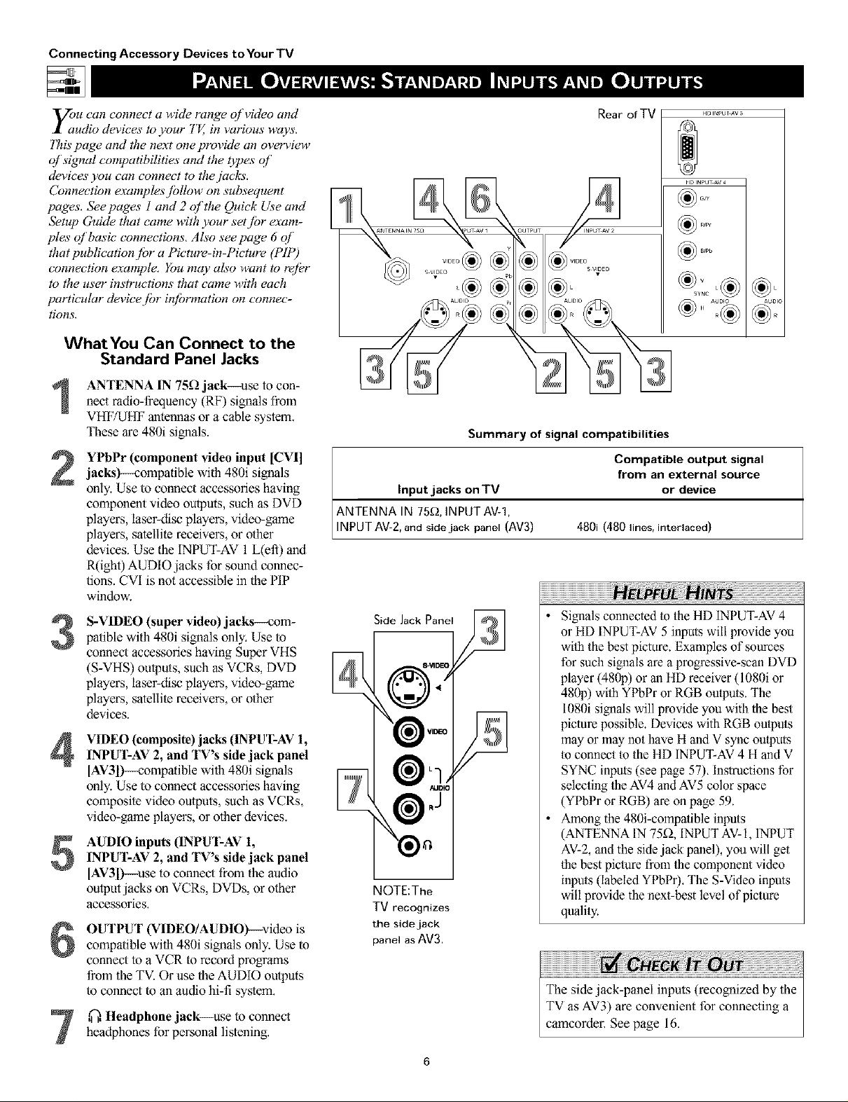
WhatYou Can Connect to the
Standard Panel Jacks
ANTENNA IN 75_ jack--use to con-nect radio-_quency (RF) signals from
VHF/UHF antennas or a cable system.
These are 480i signals.
YPbPr (component video input [CVI]jacks)--compatible with 480i signals
only. Use to connect accessories having
component video outputs, such as DVD
players, laser-disc players, video-game
players, satellite receivers, or other
devices. Use the INPUT-AV 1 L(efi) and
R(ight) AUDIO jacks for sound connec-
tions. CVI is not accessible in the PIP
window.
S-VIDEO (super video) jacks--com-
3
patible with 480i signals only. Use to
connect accessories having Super VHS
(S-VHS) outputs, such as VCRs, DVD
players, laser-disc players, video-game
players, satellile receivers, or other
devices.
VIDEO (composite) jacks (INPUT-AV 1,
4
INPUT-AV 2, and TV's side jack panel
[AV3l)--compatihle with 480i signals
only. Use to connect accessories having
composite video outputs, such as VCRs,
video-game players, or other devices.
AUDIO inputs (INPUT-AV 1,
5
INPUT-AV 2, and TV's fide jack panel
[AV3D--use to connect from the audio
output jacks on VCRs, DVDs, or other
accessories,
OUTPUT (VIDEO/AUDIO)--video is
6
compatiNe with 480i signals only. Use to
connect to a VCR to record programs
from the TV. Or use theAUDIO outputs
to connect toan audio hi-fi system,
Rear of TV
Summary of signal compatibilities
Compatible output signal
from an external source
Input jacks on TV or device
ANTENNA IN 75£_, INPUT AV-1,
INPUT AV-2, and side jack panel (AV3) 480i (480 lines, interlaced)
Side Jack Panel
NOTE:The
TV recognizes
the side jack
panel as AV3.
• Signals connected to the HD INPUT-AV 4
or HD INPUT-AV 5 inputs will provide you
wilh the best picture. Examples of sources
for such signals are a progressive-scan DVD
player (480p) or an HD receiver (1080i or
480p) wilh YPhPr or RGB ou/pu/s. The
1080i signals will provide you with the best
picture possible. Devices with RGB ou/pu/s
may or may not have H and V sync ou/puts
to connect to the HD INPUT-AV 4 H and V
SYNC inputs (see page 57). Instructions for
selecling/he AV4 and AV5 color space
(YPbPr or RGB) are on page 59.
• Among the 480i-compalible inpu/s
(ANTENNA IN 75fL INPUT AV-l, INPUT
AV-2, and the side jack panel), you will get
/he best piclure from/he component video
inpu/s (labeled YPhPr). The S-Video inputs
will provide the nexl-best level of picture
quali/y.
HD INPUT AV 5
_,o
,@,Headphone jack--use to connectheadphones for personal listening,

_jle HD INPUT-AV 4 and HD 1NPUT-AV 5
acks al!ow you to digital equipment with
1080i or 480p signal output.
Connecting Accessory Devices toYour TV
WhatYou Can Connect to the
High-definition Input Jacks
HD INPUT-AV 4_use to connect digi-
1
tal equipment with a 1080i or a 480p
signal output, such as HD receivers
(1080i or 480p) or DVD players with
progressive-acan capability (480p). You
can connect equipment with YPbPr
component video or RGB outputs to the
HD INPUT-AV 4 jacks, H and V Sync
connections may or may not he required
for RGB connections, (See page 57.)
Dedicated audio input jacks are located
with the HD INPUT-AV4 video jacks,
NOTE: The Pietare-in-Pictare (PIP) feature
is notavailable for use with AV4,
HD INPUT-AV _-use to connect digital
2
equipment with a 1080i or a 480p signal
outpul, such as HD receivers (1080i or
480p) or DVD players (480p), The HD
INPUT-AV 5 jack accepts a DB 15connec-
tor, Dedicated audio inputjacks are locat-
ed with lhe HD INPUT-AV 5 videojack,
NOTE: The Pictare-in-Pictare (PIP) feature
is notavailable for use with AV5.
Rear of TV
ANTENNA I_ _ 5_ I_UT AV 1 OUTPUT I_PUr AV
Summary of signal compatibilities
from an external source
Input jacks on TV or device
1080i (1080 lines, interlaced) or
Compatible output signal
HD INPUT-AV 4 and HD INPUT-AV 5 480p (480 line% progressive scan)
• The TV's default color-space setting for
HD INPUT-AV 4 is YPbPr, and for
HD INPUT-AV 5 it is RGB. if the picture
looks grossly incorrect, try changing the
color-space setting on either the digital
equipment or the TV, For more informa-
tion on setting the color space on the dig-
ital equipment, see the equipment's direc-
tions-for-use manual. To set the TV's
color space, see page 59 in this manual,
• This television is designed to be compatible
with high-definition signal standards 1080i
and 480p as specified by the Electronic
Industries Association standard EIA770.3.
Because output standards may v_ by man-
ufactarel; you may encounter some digital
equipment that will not properly display pic-
tures on the TV.
• The Picture-in-Picture (PIP) feature does
not function with the HD INPUT-AV 4 or
HD INPUT-AV 5 signal sources. AV4 and
AV5 cannot be displayed in the PIP win-
dow, nor can the PIP window be dis-
played when either AV4 or AV5 is being
viewed on the main screen,

Connecting Accessory Devices to Your TV
Tjhe TV _ audio/video (A V) irlputjacks provide
r directpicture and sound connections
bem'een the TV and accesso_ T devices such as
VCRs, D VD players, and others that have A V out-
putjack_.
7his example, which uses the INPUT-AV l jacks,
shows you one wuy you can connect a VCR to
your TE
R_@r to the directionszfbr-use manual./br your
VCRjbr fi_rther iqfiJmlation on connections.
7b make the connections show,n it1tbis example,
you will need:
• one coaxial cubic (75f2)
• one cablejbr a vMeo connection (standard
RCA connector)
• two cablesjbr audio connections (standard
RCA connectors) (only one cubic is needed /br
a nonstereo VCR).
NOTE: Hw cables are not supplied with your TE
You should be able to buy them at most stores
that sell electronics. Or you cun call our
Customer Cure Center at 1-800-531-0039
Connect a cable TV or antenna signal tothe ANT IN jack on the rear of the VCR.
of the VCP, to the ANTENNA IN 75D--
Connect from the OUT jack on the rear
jack on the rear of the TVI
Connect the VIDEO OUT jack on the
rear of the VCP, to the INPUT AV1
3
VIDEO jack on the rear of the TVI
Connect the audio output R(ight) and
4
L(eft) jacks on the lear of the VCR tothe
INPUT-AV 1AUDIO jacks on the real"of
the TV.
NOTE: if the VCP, is a mono (nonstereo)
unit, connect only the left audio cable,
which usually has a white connector.
Rear oIVCR
• (Example: Philips VCR
model VR674CAT)
[]
Coaxial Cable
Lead-in from
Cable TV Company
or VHF/UHF Antenna
N Pm,
To simplify making connections, audio and
video cables often have color-code connec-
tors. The jacks on your TV are likewise
color coded to match the connectors. The
coding is as follows:
• Yellow for video (composite)
• Red for the fight audio channel
• White for the left audio channel
NOTE: If your VCR is mono (non-
stereo), you will connect only one audio
cable. You must ensure that the TV is set
to MONO for the signal source to which
you've connected the VCR (INPUT-AV 1,
INPUT-AV2, or the side panel inputs
[AV3]). Otherwise, you will receive
sound from only one of the TV's speak-
ers. See page 36.
Press the AV button on the remote con-trol as many times as necessary to select
theAV1 source.
'l_rn the VCR on and press PLAY toview a videotape on the TV.
You can display the AV 1, AV2, or AV3 signal
sources in the PIP window. See pages 6 and 7
in the Quick Use and Setup Guide for infor-
mation on using/he Picture-in-Picture (PIP)
fealure. The VCR connection option shown in
/he Quick Use and Setup Guide will allow you
to use your VCR as a second, dedicated tuner
for viewing channels in the PIP window. Also
note that the PIP SWAP button allows you to
switch the main and PIP pictures.
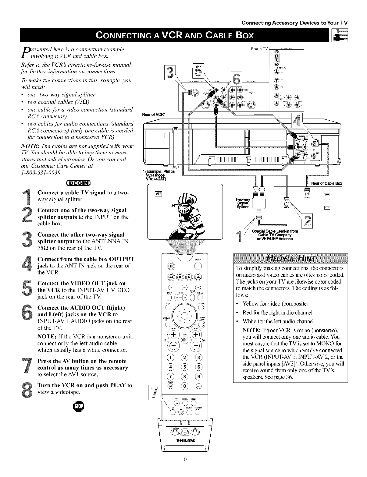
presented here is a connection example
invoh4ng a VCR and cable box.
R_ffbr to the VCR :_directionsJbr-use manual
fi_rjhrther #lfbrmation on connections.
lb make the connections in this example, you
will need."
• one, two-way signal splitter
• two coaxial cables (75£2)
• one cable.fbr a video connection lstandard
RCA connecto 0
• two cables/or audio connections (standard
RCA connectors) (only one cable is needed
jbr connection to a nonstereo VCR).
NOTE: 771e cables are not supplied with your
TE You should be able to buy them at most
stores that sell electronics. Or you can call
our Customer Care Center at
1-800-53!-0039.
cffga-
Connect a cable TV signal to a two-
1
way signal splitter,
Rear of VCR*
• Example: Philips
_CR model
VR674CA_
[]
Connecting Accessory Devices toYour TV
Rear of Cable Box
Connect one of the two-way signal
2
splitter outputs to the INPUT on the
cable box,
Connect the other two-way signalsplitter output to the ANTENNA IN
75_ on the rear of the TVI
Connect from the cable box OUTPUTjack to the ANT IN jack on the rear of
the VCR.
Connect the VIDEO OUT jack on
the VCR to the INF'UT-AV 1 VIDEO
jack on the rear of the TV,
Connect the AUDIO OUT R(ight)
and L(eft) jacks on the VCR to
INPUT-AV 1 AUDIO jacks on the rear
of the TV.
NOTE: if the VCR is a nonstereo unit,
connect only the left audio cable,
which usually has a white connector.
Press the AV button on the remotecontrol as many times as necessary
to select the AVI source,
Turn the VCR on and push PLAY to
view a videotape,
@
To simplify" malting connections, the connectors
on audio and video cables are often color coded.
The jacks on your TV are likewise color coded
Io match the connectors. The coding is as fol-
lows:
• Yellow for video (composite)
• Red for the right audio channel
• White for the left audio channel
NOTE: If your VCR is mono (nonstereo),
you will connect only one audio cable, You
must ensure that the TV isset io MONO for
the signal source to which you've connected
the VCR (INPUT-AV l, INPUT-AV 2, or the
side panel inputs [AV3]). Otherwise, you will
receive ,soundfrom only one of theTV's
speakers, Seepage 36.
PHILIPS 1,

Connecting Accessory Devices to Your TV
y_Jo u can use your TV_ AUDIO OU]PUY_ktcks
connect to an external audio kirfl system.
Fbllow [be simple steps below.
7b make these connections, you will need two
cables ]br audio connections (stumlard RCA).
NOTE: 7"becables are not supplied with your TE
You shouhl be able to buy them at most stores
that sell electronics. Or you cun call our
Customer Cure Center at 1-800-531-0039.
Connect from the L(eft)and R(ight)AUDIO OU'I PUTjacks onthe rear of the
TV tothe L(eft)and R(ight)AUX/TV
INPUTjacks on therearof thehi-fi system.
AUDIO OUT control,
See the section below on using the
After connecting the TV;_ AUDIO OU]7_UT
lacks to the AUDiO INPUT jacks on an
external hi:f! system, set the AUDIO OUT
control in the SOUND submenu to either
VARIABLE or FIXED to determine whether
you ac_]ust the volume at the TV or at the
external hizf! system. 7b change the volume at
llw TV using the TV'_ remote control, you must
select VARIABL£ 7b adjust the volume at the
stereo using the hizf!'s controls, you must select
FIXED. You can also use the SPEAKERS
control in the SOUND submenu to turn the
TV_Yspeakers q[_'
on the remote control to show the
Press the MENU/SELECT button
onscreen menu,
Press the CURSOR RING DOWN
once to highlight SOUND.
Press the CURSOR RING RIGHT
to enter the SOUND submenu.
3
Press the CURSOR RING DOWN
4
repeatedly until AUDIO OUT is high-
lighted,
Press the CURSOR RING LEFT or
RIGHT to set the AUDIO OUT to
5
either VARIABLE or FIXED,
If you want to turn the TV's internal
speakers off, press the CURSOR
6
RING DOWN repeatedly until
SPEAKERS is highlighted. Then press
the CURSOR RING LEFT or RIGHT
to turn the speakers off.
Press the STATUS/EXIT button to
exit the menu.
7
• PICTURE TREBLE
_:_ BASS
• FEATURES BALANCE
• INSTAL[ AVL
INCR'SURROUND
PHILIPS
Rear of TV
• BALANCE
• AV[
• INCR'SURROUND
t
SOUND
INCR.SNRRONND
• HEADPHONE
• SIEREO
• SAP
lldlllllUll ,_ ==
ltlllll[I [I ]=,ul[t[_t,
SOUND
NHEADPHONE
•SIEREO
• SAP
• AUDIOOUT
• 1_ i_ k{|! 131
I
i
i
ill
I
[]
iiiiiiiiiiiiiiiiiiiiiiiiiiiiiiiiiiiiiiiiiiiiiiiiiiiiiiiiiiiiiiiiiiiiiiiiiiiiiiiiiiiiiiiiiiiiiiiiiiH__ _I!I!!_IH!_I!_I_I_I_I_I_I_I_I_I_I_I_I_I_I_I_I_I_I_I_I_I_I_I_I_I_I_I_I_I_I_I_I_I_I_I_I_I_I_I_I_I_I_I_I_I_I_I
The sound ouqTuts from the TV to an exter-
nal hi-fi system are not afi'ec_ed or tailored
by the TREBLE, BASS, BALANCE, AVL,
INCR. SURROUND, and BASS BOOST
controls in the TV's SOUND submenu.
iO

C:mponent video inputs allow the highest pos-
ible color and picture resohttion in the play-
back of digital signals, such as those of DVD
players. 17re color dtfference signals (Pb, Pr) and
the luminance Or)sigmal are connected and
received separately. ITte result i_ better color
bandwidth in[brmation than is possible with com-
posite video (lubeled VIDEO on your TV_juck
panel) or S-Video connections.
7b make the connections show,n #_ this example,
you w,ill need:
• three cablesjbr video connections (stundurd
RCA connectors)
• two cablesjbr audio connections (standard
RCA connectors).
NOTE: The cables are not supplied with your TI_
You should be able to buy them at most stores
that sell electronics. Or you con call our
Customer Cure Center at 1-800-531-0039.
r-ffffgr
Connect the YPbPr (component)
1
VIDEO OUT jacks from the DVD player
to the INPUT-AV 1YPbPr (component
video) jacks on the rear of the TV.
NOTE: The INPUT-AV 1YPbPr jacks
will accept 480i (interlaced) output sig-
nals only. The connection example on this
page assumes the use ofa DVD player
with interlaced output. Some DVD play-
ers, howevel; have YPhPr outputs that can
be switched between interlaced and pm-
gessive scan. If you are attempting to use
a DVD player with progressive-scan
(480p output) capability to make the con-
nection shown in this exmnple, you must
be sure to switch the DVD player to inter-
laced. If necessau, refer to the DVD play-
er's directions-fol_use manual for help. if
you want to use the DVD player in pro_
_essive-scma mode, you must use the
HD INPUT-AV4 jacks (see page 12).
Connect the AUDIO OUT L(eft) andR(ight) jacks from the DVD player to the
INPUT-AV 1AUDIO jacks on the rear of
the TV:
Press the AV button on the remote con-trol as many times as necessary to select
the CVI (component video input) source
on the TV.
Connecting Accessory Devices toYour TV
*(Example: Philips DVD model DVD712)
[]
• To simplify making connections, the con-
nectors on audio and video cables are
often color coded. The jacks on your TV
are likewise color coded to match the
connectors.
• The names for ihe component video jacks
may differ depending on the DVD player
or accessory digital source equipment
used. For example, besides YPbPr, you
may see R-Y/B-Y/Y; or CrCbY. Although
abbreviations and termsmay vary, the let-
ters B and R stand for the blue and red
color component signal connectors, respec-
tively, and Y indicates the luminance sig-
nal. lfneces_ry, refer to the directions-for-
use manual for your DVD or digital acces-
sory for more information,
• You can also connect a satellite receiver
to the TV in a manner similar to the
example shown on this page. if you con-
nect a satellite receiver to the TV, you
will need to use the receiver's channel-
memorization system to store channels in
the receiver's memory,
• if you experience difficuliies receiving
sound with a DVD disc, check the sound
settings through the DVD disc's menu.
• CVI is not accessible in the PIP window,
See pages 6 and 7 in the Quick Use and
Setup Guide formore on the PiP feature,
Turn the DVD player on and pressPLAY to view the DVD program on the
TV.
I_HILIPS
11
Connecting Accessory Devices toYour TV
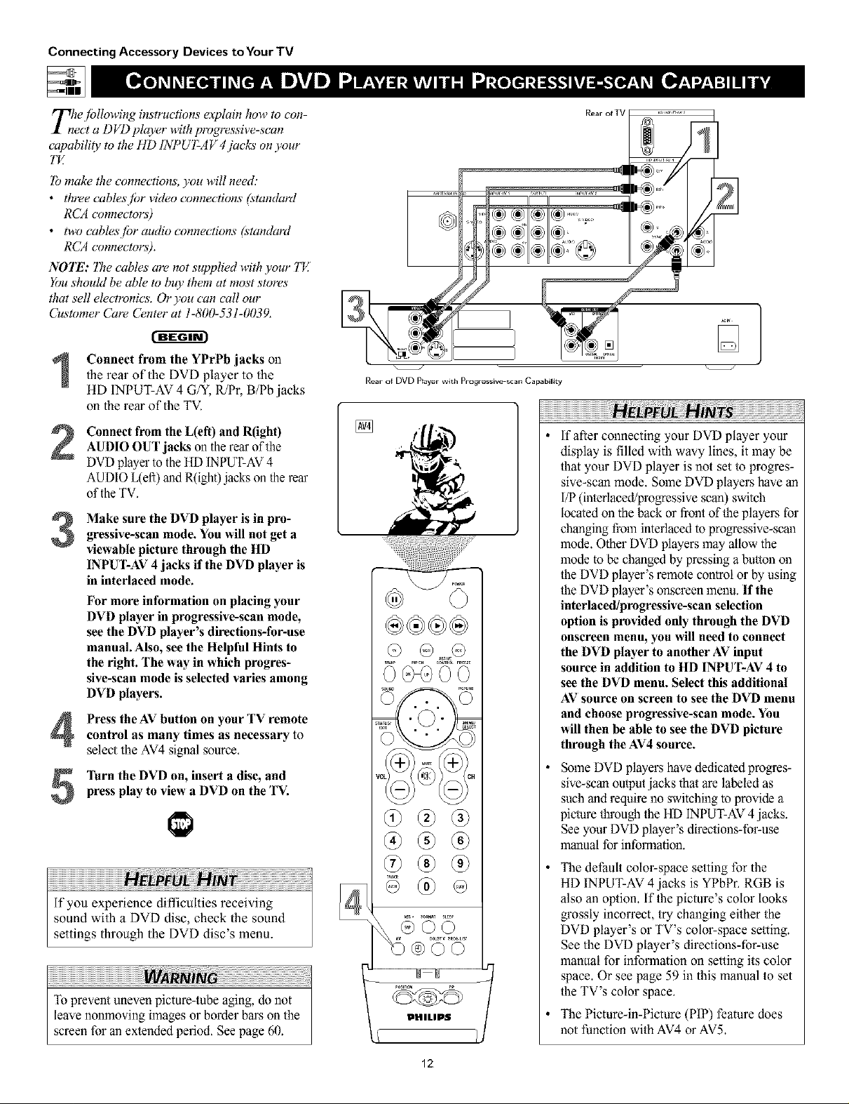
T_le./bllowing instructions explain how to con-
ect a DVD player w,ithp_vgressive-scan
capability to the HD [NPUT-A V 4jacks on your
"lbmake the connections, you w,ill need:
• three cables/br video connections (standurd
RCA connectors)
• two cablesjbr audio connections (standard
RCA connectors).
NOTE: Tbe cables are not supplied with your TI_
You should be able to buy them at most stores
that sell electronics. Or you con call our
Customer Cure Center at 1-800-531-0039.
]
Connect from the YPrPb jacks onthe rear of the DVD piayer to the
HD INPUT-AV 4 G/Y, R/Pr, B/Pb jacks
on the rear of the TV.
Connect from the L(efi) and R(ight)AUDIO OUT jacks on the rear of the
DVD playep to the HD INPUT-AV 4
AUDIO L(efi) and R(ight)jacks on the reap
of the TV.
Make sure the DVD player is in pro-
gressive-scan mode. You will not get a
3
viewable picture through the HD
IN PUT-AV 4 jacks if the DVD player is
in interlaced mode.
For more information on placing your
DVD player in progressive-scan mode,
see the DVD player's directions-for-use
manual. Also, see the Helpful Hints to
the right. The way in which progres-
sive-scan mode is selected varies among
DVD players.
Press the AV button on your TV remotecontrol as many times as necessary to
select the AV4 signal source.
press play to view a DVD on the TV.
Turn the DVD on, insert a disc, and
If you experience difficulties receiving
sound with a DVD disc, check the sound
settings through the DVD disc's menu.
Rear of DVD Prayer with Progressive scan Capability
ki_, ',
®
®
If after connecting your DVD player your
display is filled with wavy lines, it may be
that your DVD player is not set to progres-
sive-scan mode. Some DVD players have an
I/P (interlaced/progressive scan) switch
located on the back or front of the playel\s for
changing fiz)minterlaced to progressive-scma
mode. Other DVD players may allow the
mode to bechanged by pressing a button on
the DVD player's remote control or by using
the DVD player's onscreen menu. If the
interlaced/progressive-scan selection
option is provided only through the DVD
onscreen menu, you will need to connect
the DVD player to another AV input
source in addition to HD INPUT-AV 4 to
see the DVD menu. Select this additional
AV source on screen to see the DVD menu
and choose progressive-scan mode. You
will then be able to see the DVD picture
through the AV4source.
Some DVD players have dedicated progres-
sive-scan output jacks that are labeled as
such and require no switching to provide a
picture through the HD INPUT-AV4 jacks.
See your DVD player's directions-fol_use
manual for information.
The default colol_space setting for the
HD INPUT-AV 4 jacks is YPbPr. RGB is
also an option. If the picture's color looks
grossly incorrect, try changing either the
DVD player's or TV's color-space setting.
See the DVD player's directions-for-use
manual for information on setting its color
space. Or see page 59 in this manual to set
the TV's color space.
The Picture-in-Picture(PIP) feature does
not function with AV4 or AV5.
12

rlWhe S01per)-Fhleo connection on the rear (and
I side pa.el) qf the TV carl give you better pic-
ture detail aM clar#y.fbr the pluyback qf S-VHS
VCR tapes" or DVDs than the normal antenna
(RF signal) or Video (composite) picture connec-
tions. ]he example given connects a D VD/VCR
Cbmbi unit to the 1NPUT-AV2juck_ on the rear
qf the TE
NOTE: The accessory device must have an
S- VIDEO output jack to mak_ the connection
explained on this page.
]b make the connections, you w,illneed:
• one S-_'deo cable
• two cablesjbr audio connections (standard
RCA connectors).
NOTE: The cables are not supplied with your TE
You should be able to buy them at most stores
that sell electronics. Or you cun call our
Customer Cure Center at 1-800-531-0039.
Connecting Accessory Devices to Your TV
®
............................... :i
®_ ,_ _,
S-VIDEO Output*
(Example: Philips DVDNCR Combi model DV910VHS)
Connect the S-VIDEO OUT jack on therear of the accessory device with
S-VIDEO outputto theINPUT-AV 2
S-VIDEO jack on the rear of theTV.
Connect the DVD/VCR AUDIO OUTjacks on the rear of the accessory device
to the INPUT-AV2 AUDIO input jacks on
the rear of the TV.
Press the AV button on the remote con-trol as many times as necessary to select
the AV2 source on the TVI
]'urn the accessory device on and pressplay to view the video source material
(DVD or videotape, for example) on the
TV.
[]
To simplify making connections, audio
cables are often color coded: red for the
right channel, and while for the left chan-
nel, The jacks on your TV are likewise
color coded to match the connectors. To
make S-Video connections, you must use
an S-Video cable,
You can also connect a satellite receiver,
laser-disc player, video-game player, or
other accessory device with S-Video
capability to the TV in a manner similar
to example shown on this page.
if you connect a satellite receiver to the
TV, you will need to use the receiver's
channel-memorization system m store
channels in the receiver's memory,
Video sources tha_show a constant nonmoving
pattern on the TV screen can cause picture-tube
damage. When you are not using your video
accessory devices, tam them off:Also, regular-
ly allemate the use of accessory video sources
with normal TV viewing. See page 60.
13
Connecting Accessory Devices to Your TV
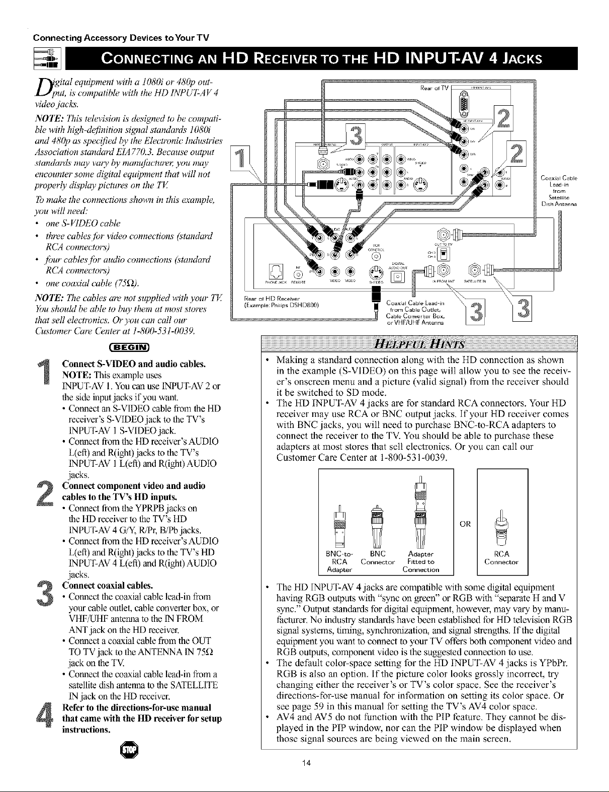
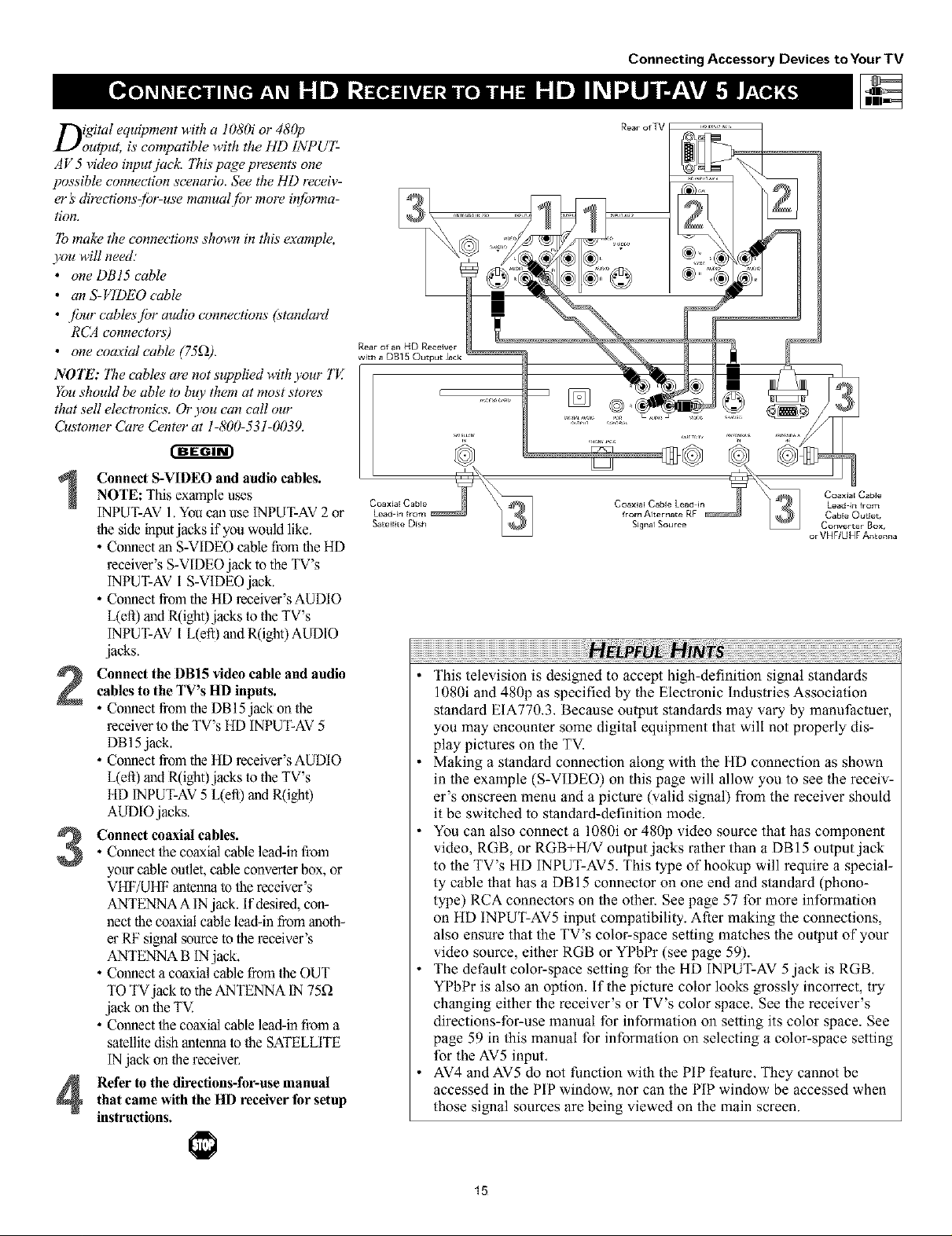
D;gital equipment w,ith a 1080i or 480p out-
ut, is compatible w,ith the HD INPUT-AV 4
video jacks.
NOTE: This television is desigmed to be compati-
ble with high-de/inition sigmal standards 1080i
and 480p as spec!fied by the Electronic Industries
Association standard E[A 770.3. Because output
standards may vao_ by mam(/hcture_; you may
encounter some digital equipment that w,ill not
properly display pictures on the TJ_
7b make the connections show,n #1 this example,
you will need:
• one S-VIDEO cable
• three cablesjbr video connections (standard
RCA connectors)
• fimr cablesjbr audio connections (standard
RCA connectors)
• one coaxial cable (75_2).
NOTE: "lT_ecables are not supplied with your TJ_
You should be able to buy them at most stores
that sell electronics. Or you can call our
Customer Cure Center at 1-800-531-0039.
Connect S-VIDEO and audio cables.NOTE: This example uses
INPUT-AV I. Youcan useINPUT-AV 2 or
the side inputjacks if you want
• Connect an S-VIDEO cable fi'om the HI)
receiver's S-VIDEO jack to the TV's
INPUT-AV 1 S-VIDEOjack.
• Connect from the HD receiver's AUDIO
l/eft) andR(igbt)jacksto the TV's
INPUT-AV 1l/eft) andR(ight)AUDIO
jacks.
(Example: Philips DSHDS00)
Making a standard connection along with the HD connection as shown
in the example (S-VIDEO) on this page will allow you to see the receiv-
er's onscrcen menu and a picture (valid signal) from the receiver should
it be switched to SD mode.
The HD INPUT-AV 4 jacks are for standard RCA connectors. Your HD
receiver may use RCA or BNC output jacks, if your HD receiver comes
with BNC jacks, you will need to purchase BNC-m-RCA adapters to
connect the receiver to the TV. You should be able to purchase these
adapters at most stores that sell electronics. Or you can call our
Customer Care Center at 1-800-531-0039.
w
Coaxia[ Cable
Lead-in
Connect component video and audiocables to the TV's HD inputs.
• Comaectfromthe YPRPB jacks on
the HD receiverto theTV's HI)
INPUT-AV4 G/Y,R/P_;B/Pb jacks.
• Comaectfrom the HD receiver's AUDIO
I/eft) and R(igbt)jacks to the TV's HI)
INPUT-AV4 l/eft) and R(ight)AUDIO
jacks.
• Connect the coaxial cable lead-in from
Connect coaxial cables.
your cable outlet, cable converter box, or
VHF/UHF antermato the IN FROM
ANTjack on the HI) receivel:
• Cormect a coaxial cable fl'om the OUT
TO TV jack to the ANTENNA IN 75_Q
jack on theTV.
• Cormect the coaxial cable lead-in from a
satellite disb antenna to the SATELLITE
INjack on the HD receiver.
Refer to the directions-for-usemanualthat came with the HD receiver for setup
instructions.
OR
BNC-to- BNC Adapter
RCA Connector Fitted to
Adapter Connection
RCA
Connector
The HD INPUT-AV 4 jaclcs arc compatible with some digital equipment
having RGB outputs with "sync on green" or RGB with "separate H and V
sync." Output standards for digital equipment, however, may vary by manu-
f:acturer.No industry standards have been established for HD television RGB
signal systems, timing, synchronization, and signal strengths. If the digital
equipment you want to connect to your TV offers both component video and
RGB outputs, component video is the suggested connection to use.
The default color-space setting for the HD INPUT-AV 4 jacks is YPbPr.
RGB is also an option. If the picture color looks grossly incorrect, try
changing either the receiver's or TV's color space. See the receiver's
directions-for-use manual for information on setting its color space. Or
see page 59 in this manual for setting the TV's AV4 color space.
AV4 and AV5 do not function with the PIP feature. They cannot be dis-
played in the PIP window, nor can the PIP window be displayed when
those signal sources are being viewed on the main screen.
14
Digital equipment with a 1080i or 480p
output, is compatible with the HD INPUT-
AV 5 video input jack. ]71ispage presents one
possible connection scenario. See the HI) receiv-
er's directionszf!Jr-use manual /br more in/brma-
tion.
]b makz_the connections shown in this exat_q)le,
you will need:
• one DBI5 cable
• anS-VIDEO cable
• /bur cables./br audio connections (standard
RCA connectors)
• one coaxial cable 175£2).
NOTE: "171ecables are not supplied with your TE
You shouM be able to buy them at most stores
that sell electronics. Or you can call our
Customer Care Center at 1-800-531-0039.
Connect S-VIDEO and audio cables.NOTE Th's example uses
INPUT-AV 1.You can use INPUT-AV 2or
the side inptajacks if you would like.
• Connect an S-VIDEO cable from theHD
receiver's S-VIDEOjack to the TV's
INPUT-AVi S-VIDEO jack.
• Connect from the HI) receiver's AUDIO
L(efi) aud R(ight)jacks to the TV's
INPUT-AV l L(eft) and R(ight) AUDIO
jacks.
Connect the DBI5 video cable and audiocables to the TV's HD inputs.
• Connect from the DB 15jack onthe
receiver to the TV'sHD INPUT-AV5
DB15jack.
• Connect from the HI) receiver's AUDIO
L(efi) madR(ight)jacks to the YV's
HI) INPUT-AV5 L(efl) madR(ight)
AUDIO jacks.
• Connect the coaxial cable lead-in from
Connect coaxial cables.
your cable outlet, cable converter box, or
VHF/UHF matennato the receiver's
ANTENNA A INjack. If desired, con-
nect the coaxial cable lead-in from maoth-
er RF signal ,sourceto the receiver's
ANTENNA B IN jack.
• Connect a coaxial cable from the OUT
TO TVjack to the ANTENNA IN 75£2
jack on the TV.
• Connect the coaxial cable lead-in from a
satellite dish antenna to the SATELLITE
INjack on the receiver.
Refer to the directions-for-use manualthat came with the HD receiverfor setup
instructions.
Connecting Accessory Devices to Your TV
or VHFIUHF Antenna
This television is designed to accept high-definition signal standards
1080i and 480p as specified by the Electronic Industries Association
standard EIA770,3, Because output standards may vary by manufiactuer,
you may encounter some digital equipment that will not properly dis-
play pictures on the TV.
Making a standard connection along with the HD connection as shown
in the example (S-VIDEO) on this page will allow you to see the receiv-
er's onscreen menu and a picture (valid signal) from the receiver should
it be switched to standard-definition mode.
You can also connect a 1080i or 480p video source that has component
video, RGB, or RGB+H/V output jacks rather than a DBI5 output jack
to the TV's HD INPUT-AV5. This type of hookup will require a special-
ty cable that has a DBI5 connector on one end and standard (phono-
type) RCA connectors on the other. See page 57 for more information
on HD INPUT-AV5 input compatibility. After making the connections,
also ensure that the TV's color-space setting matches the ouq_ut of your
video source, either RGB or YPbPr (see page 59).
The default color-space setting for the HD INPUT-AV 5 jack is RGB,
YPbPr is also an option, if the picture color looks grossly incorrect, try
changing either the receiver's or TV's color space, See the receiver's
directions-for-use manual for information on setting its color space. See
page 59 in this manual for information on selecting a color-space setting
for the AV5 input,
AV4 and AV5 do not function with the PIP feature, They cannot be
accessed in the PIP window, nor can the PIP window be accessed when
those signal sources are being viewed on the main screen.
15

Connecting Accessory Devices to Your TV
Tjbhe side panel jacks provide a convenient w,ay
r you to connect a camcorder to your TH
]he side paneljucks are recognized by your TV
as AV&
You cun obtairl S-VIDE()quulity with an S-VHS,
Hi-& or digital camcorder by connectiHg to the
S-VIDEO input insteud qf the V1DEO (composite)
iHput.
]b make the connections show,n in this example,
you will need."
• an S-VIDEO cable
• two cablesjbr audio connections (standard
RCA connectors).
NOTE: The cablex art, not supplied with your TH
You should be able to buy them at most stores
that sell electronics. Or you cun ca# our
C_stomer Cure Center at 1-800-531-0039.
Connect from the S-VIDEO output onthe camcorder to the S-VIDEO input in
the TV's side panel.
Connect from theAUDIO outputs on
the camcorder to the side panel AUDIO
L(eft) and R(ight) inputs.
H ,rut
To simplify making connections, the con-
nectors on audio cables are often color
coded: red for the right channel, and white
for the left channel. The jacks on your TV
are likewise color coded to match the con-
nectars, To make S-Video connections, you
must use an S-Video cable,
Press the AV button on the remote con-trol as many times as necessary to select
the AV3 source on the TV.
]'urn the camcorder on, insert a video-tape and press PLAY to view the tape
on the TV.
®®®®
Q @
(9@@
®®®
®®®
®®
16
Connecting Accessory Devices to Your TV
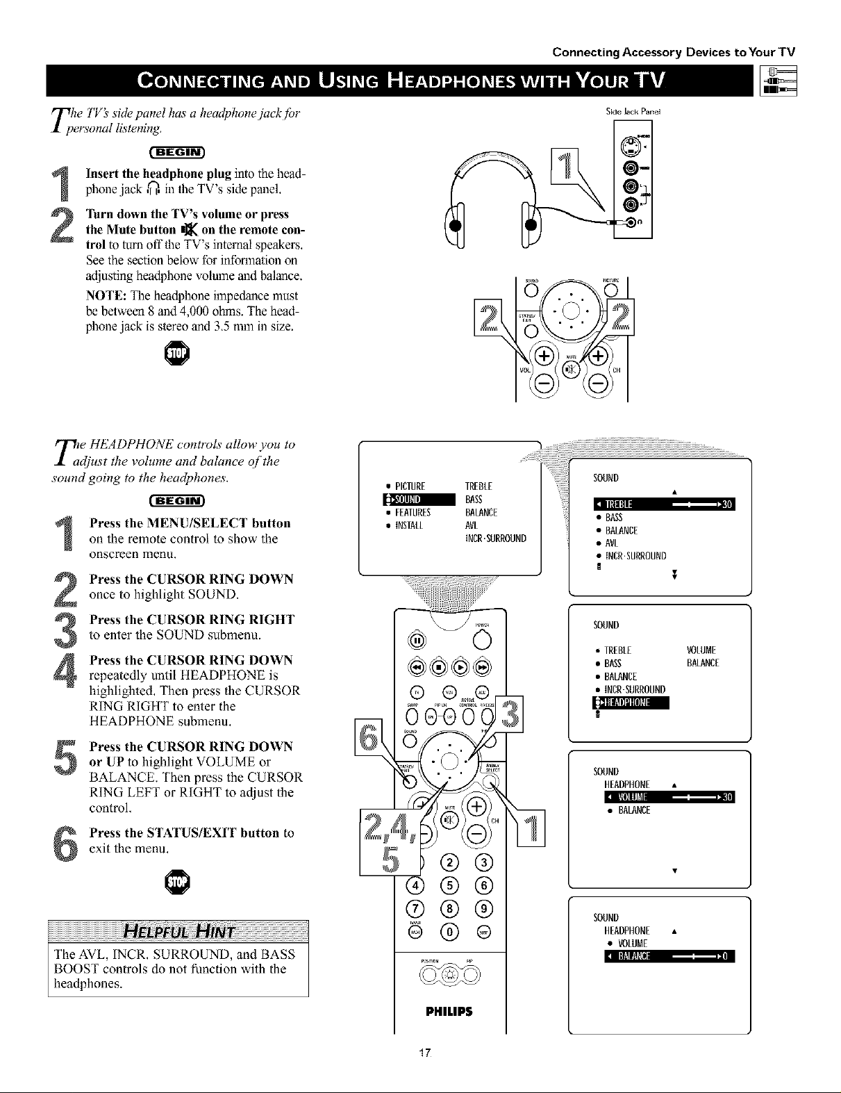
Tphe TV_ side panel has a headphonejuck flJr
ersonal listening.
Insert the headphone plug into the head-phone jack ,_, in the TV's side panel.
the Mute button _ on the remote con-
]'urn down the TV's volume or press
trol to turn offthe TV's internal speakers,
See the section below for infon_nationon
adjusting headphone volume and balance,
NOTE: The headphone impedance must
be between 8 and 4,000 ohms. The head-
phone jack is stereo and 3,5 mm in size.
T£e HEADPHONE controls allow you to
djust the volume and balance of the
sound going to the headphones.
on the remote control to show the
Press the MENU/SELECT button
onscreen menu.
Press the CURSOR RING DOWNonce to highlight SOUND.
Press the CURSOR RING RIGHT
to enter the SOUND submenu.
3
Press the CURSOR RING DOWN
4
repeatedly until HEADPHONE is
highlighted, Then press the CURSOR
RING RIGHT to enter the
HEADPHONE submenu,
• PICTURE TREBLE
BAg
• FEATURES BALANCE
• INSTALL AVL
{NCR.SURROUND
®®®®
Side Jack Panel
SOUND
• BASS
• BALANCE
• AVL
• INCR.SURROUND
$
SOUND
• TREBLE VOLUME
• BASS BALANCE
• BALANCE
• INCR'SURROUND
[:_BiIfllIoRPI
Press the CURSOR RING DOWN
5
or UP to highlight VOLUME or
BALANCE. Then press the CURSOR
RING LEFT or RIGHT to adjust the
control,
exit the menu,
Press the STATUS/EXIT button to
The AVL, INCR, SURROUND, and BASS
BOOST controls do not ffmction with the
headphones.
®®®
®®
PHILIPS
17
SOUND
HEADPHONE •
a IIil] Ill_ ,= II
• BALANCE
SOUND
HEADPHONE •
• VOLUME
:1I lti!!l
Using the Remote Control
y;ur TV remote is capable of working not
nly your TV but also other iq/?ared
remote (1R) controlled devices such as VCRs,
cable TV converter boxes, satellite receivers,
D VD players, and laser-disc players,
If you want to use your TV remote to oper-
ate a VCR or other accessory device, you
will need to perform this initial check
explained in this section. You may also need
to go W the sections on the "Code-entry
Method" and the "Search Method" in the
pages that fidlow.
mode button on the TV remote for
Press the VCR orACC(essory)
the desired accessory device category.
NOTE: Pressing the VCR mode button
allows access Io product codes for
VCRs, Pressing the ACC(essory) mode
button allows access Io lhe product
codes for cable TV converters, satellile
receivers, DVD players, and laser-disc
players,
Satellite R_zeiver
Cable Converter Box
DVD Player
VCR
Point the TV remote toward thedesired accessory device and press
the POWER button.
Does the remote turn the accessory
device on?
If yes, [_] and try other function but-
tons on _e TV remote. With a VCR,
for example, try the Play, Stop, and
Rewind buuons, for example. (See
page 23 for information on how the
remote bultons correspond with acces-
sory device functions.) If they also
work the accessory device, then the
remote is ready and no further steps
are needed.
If not, do the following:
Look up a four-digit remote code
number on pages 21 or 22 for your
brand of accessory device. Then go
through the simple steps for entering a
four-digit code as explained on
page 19.
®@@
@@@
®@@
iiiiiiiiiiiiiiiiiiiiiiiiiiiiiiiiiiiiiiiiiiiiiiiiiiiiiiiiiiiiiiiiiiiiiiiiiiiiiiiiiiiiiiiiiiiiiiiii iH ! !! !! !! i!i Hi i : i: i: i: i: i: i: i: i: i: i: i: i: i: i: i: i: i: i: i: i: i: i: i: i: i: i: i: i: i: i: i: i: i: i: i: i: i: i: i: i: i: i: i: i: i: :i
if more than one four-digit code number is
listed, you may have to try more than the
first number given to locate your device's
correct code,
PHILIPS
18

Using the Remote Control
Nd w that you have looked up the./bur-
igit remote-control Direct-entJ T Code
/or your brand q/accessory device, you are
read), to .follow the simple steps shown below
to program your "l'Vremote.
Please read through all the steps beJbre
beginning.
First, press and hold down the VCR
1
or ACC (for an accessory device
other than a VCR) mode button on
the TV remote, Then press and hold
down the MENUTSELECT button at
the same time for a brief moment,
Release the buttons, The TV remote
back light will switch on,
NOTE: For correct operation, you
must first press and hold the mode
butlon and then press and hold the
MEN U/SELECT button simultaneously.
Within 30 seconds of pressing the
2
VCR (or ACC) button and
MENU/SELECT button, enter a
four-digit code for the accessory
device (see pages 21 and 22),
if you make a mistake while atlempt-
ing to enler the four-digit code and
want io start again, press any button
other than one with a number, Then
relurn to step I to begin again.
Satelli'te Receiver
Cable Converter Box
DVD Player
Immim_l Immnmnm I
VCR
Point the remote at the accessorydevice. Then press the POWER but-
ton on the remote to turn the device
on,
If you do not enter a complete code within
30 seconds, you will need to perform step
1 of the Code-entry Method again.
If you enter more than four digits, the unit
will retain the first four digits entered.
If the procedure explained above does not
work the first time, repeat the steps using
the same remote code number.
• If after a second try the remote does not
operate your accessory device, and more
code numbers are listed for your brand,
use the next lisled code number.
• If after repeated attempts the Entry-code
Method does not allow you to work your
accessory device with your TV remole, try
the Search Method explained on the next
page,
®®®
®®®
®®®
®®®
PHILIPS
19
Using the Remote Control
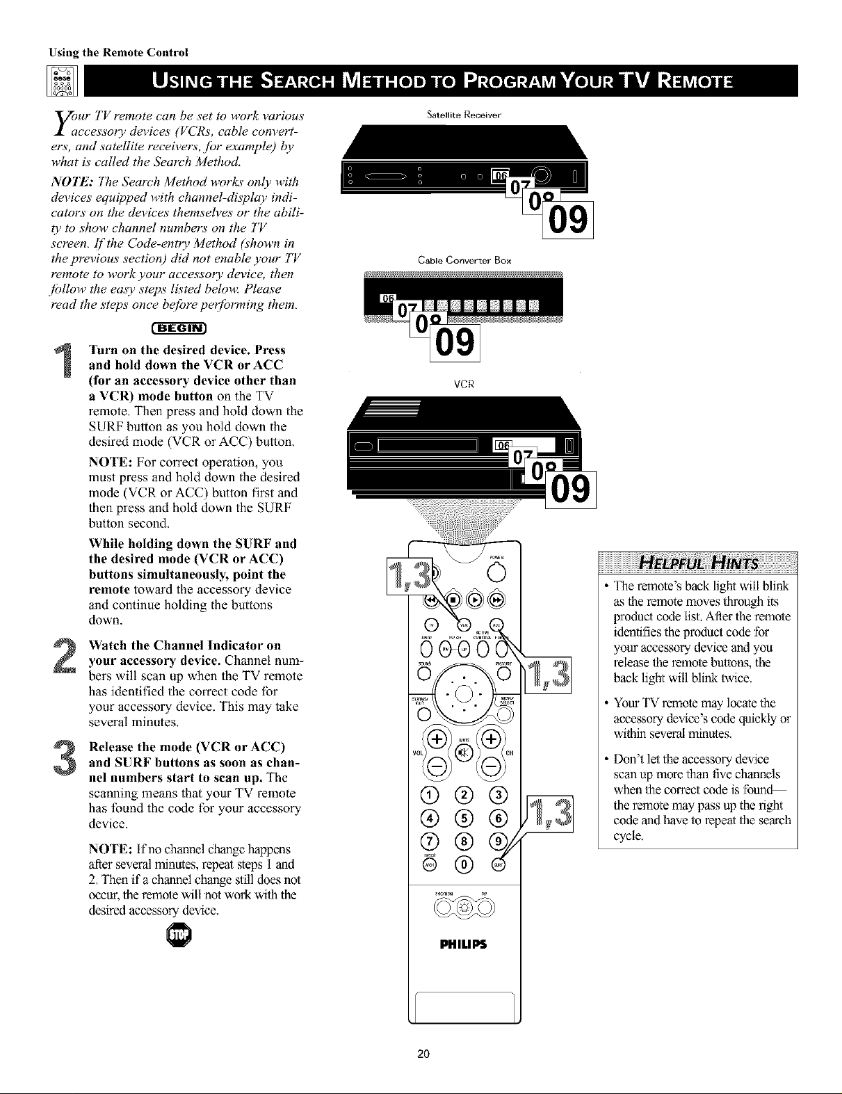
y;ur TV remote can be set to work various
ccessory devices (VCRs, cable com,ert-
ers, and satellite receivers, ./or example) 1)y
what is called the Search Method,
NOTE: The Search Method works" only with
devices equipped with channel-display indi-
cators on the devices themseh,es or the abili-
ty to show channel numbers on the TV
screen, If the Code-entry Method (shown in
the previous section) did not enable your TV
remote to work your accessory device, then
/ollow the emy steps listed beloua Please
read the steps" once bejbre per/brming them,
r-ffffffr
'lurn on the desired device. Press
and hold down the VCR or ACC
1
(for an accessory device other than
a VCR) mode button on the TV
remote, Then press and hold down the
SURF button as you hold down the
desired mode (VCR or ACC) button,
NOTE: For correct operation, you
must press and hold down the desired
mode (VCR or ACC) button first and
then press and hold down the SURF
button second.
While holding down the SURF and
the desired mode (VCR or ACC)
buttons simultaneously, point the
remote toward the accessory device
and continue holding the bunons
down.
Watch the Channel Indicator on
2
your accessory device. Channel num-
bers will scan up when the TV remote
has identified the correct code for
your accessory device. This may take
several minutes,
Release the mode (VCR or ACC)
and SURF buttons as soon as chan-
3
nel numbers start to scan up. The
scanning means that your TV remote
has found the code for your accessory
device.
NOTE: If no channel change happens
after several minutes, repeat steps 1 and
2, Then if a channel change stilldoes not
occur, theremole will not work wilh the
desired accessory device,
Satellite Receiver
Cable Convert_r Box
VCR
The remote's back light will blink
as the remote moves through its
product code list. After the remole
identifies the product code for
your accessory device and you
release the remole buttons, the
back light will blink twice.
Your TV remote may locate the
accessory device's code quickly or
within several minutes,
Don't let the accessory"device
scan up more than five channels
when the correct code is fotmd
1heremote may pass up the right
code and have 1orepeat 1hesearch
cycle,
2O
PHILIPS

ADMIRAL............... 0075, 0236
ADVENTURA ............. 0027
CODE NUMBER
AIKO .................. 0305
AIWA ................. 0334,0495, 0027, 0064
AKA=.................. 0133, 0080, 0068,0076,
..................... 0088,0183, 0269
AMERICAACTION ......... 0305
AMERICAN HIGH .......... 0062
ASHA ................. 0267
AUDIOVOX.............. 0064
BEAUMARK .............. 0267
BELL& HOWELL.......... 0131
BROKSONIC............. 0148,0211, 0029, 0236,
..................... 0238,0322, 0388, 0506
CCE .................. 0099,0305
CAUX ................. 0064
CANON ................ 0194, 0062, 0129
CAPEHART .............. 0047
CARVER ................ 0108
C]NERAL ............... 0305
CmZEN ................ 0305, 0064
COLT ................. 0099
CRAIG................. 0064, 0099, 0074,0267,
..................... 0298
CURTISMATHES.......... 0062, 006& 0087, 0189
CYBERNEX .............. 0078,0267
DAEWOO............... 0305,0588, 0047, 0072
DAYTRON.............. 0047
DEMON................ 0069
DYNATECH .............. 0027
[LECTROHOME ........... 0064
ELECTROPHONIC .......... 0064
[MEREX................ 0059
EMERSON............... 0211,0029, 0236, 0305,
..................... 0063,0148, 0238, 0588,
..................... 0235,0321, 0506, 0088,
..................... 0115,0239, 0027, 0064,
..................... 0070,0095, 0322, 0388,
..................... 0537
FISHER................. 0074,0131, 0081, 0093
FUJI................... 0060, 0062
FUNAI ................. 0027
GE ................... 0062, 0087, 0075,0092,
..................... 0229,0267
GARRARD .............. 0027
Go VIDEO .............. 0306, 0459, 0553,0259
GOLDSTAR.............. 0064, 0045, 0065,0498,
..................... 0507
GRADIENTE ............. 0035, 0027, 0435
GRUNDIG............... 0222
HI Q ................. 0074
HARLEY DAVEDSO N ........ 0027
HARMAN/KARDON ........ 0085, 0102, 0108
HARWOOD ............. 0095, 0099
HEADQUARTER........... 0073
HITACHI................ 0069,0193, 0132, 0092,
..................... 0027,0068, 0109
HUGHES NETWORK SYSTEMS .0069
JVC .................. 0094, 0035, 0233, 0234,
..................... 0068,0411
VCR
JENSEN ................. 0068
KEC .................. 0064, 0305
KLH .................. 0099
KENWOOD ............. 0068, 0094,0411,0065
KODAK ................ 0062, 0064
LXI ................... 0064
LLOYD'S................ 0027, 0235
LOGEK................. 0099
M61 .................. 0062
MGA ................. 0070, 0088, 0267
MGN TECHNOLOGY....... 0267
MTC ................. 0027, 0267
MAGNASONIC ............ 0305
MAGNAVOX ............. 0062, 0108, 0137,0130,
..................... 0027, 0066, 0176
MAGNIN ............... 0267
MARANrz .............. 0108, 0062
MARTA................. 0064
MATSUSHITA............. 0082, 0189, 0481
MEMOREX.............. 0131,0074, 0506, 0027,
..................... 0084, 0075, 0062, 0073,
..................... 0287, 0334, 0066, 0189,
..................... 0236, 0481,0828, 0829
MINOLTA............... 0132, 0069
MITSUBISHI .............. 0200, 0088, 0102,0241,
..................... 0269, 0070, 0075, 0094,
..................... 0470
MOTOROLA............. 0062, 0075
M ULTITECH ............. 0027, 0099
MAD ................. 0085
NEC .................. 0065, 0067,0068, 0077,
..................... 0094, 0109, 0131
N_KKO ................. 0064
N_KON ................ 0081,0280
NOBLEX ............... 0267
OLYMPUS............... 0082, 0253
OPTIMUS............... 0189, 0481,0827, 082&
..................... 0075, 0085, 0829, 0064,
..................... 0131,0459
OPTONICA .............. 0089
ORION ................ 0508, 0029,0211, 0236,
..................... 0322
PANASONJC............. 0082, 0189,0828,0481,
..................... 0253, 0104, 0405, 0829,
..................... 0129, 0252, 0254, 0273,
..................... 0827
PENNEY................ 0082, 0267,0064, 0069,
..................... 0085, 0067, 0081
PENTAX................ 0089, 0092, 0132
PHmCO................ 0082, 0238,0506
PHmmS................. 0108, 0062,0089,0137,
..................... 0830, 0831
PILOT ................. 0064
PIONEER ............... 0085, 0195, 0094
POLKAUDIO ............ 0108
PORTLAND .............. 0047
PROFITRO NIC ............ 0267
PROSCAN............... 0087, 0229
PROTEC................ 0099
PULSAR................ 0086, 0078
QUARTER ............... 0073
Using the Remote Control
QUARTZ ............... 0073
QUASAR ............... 0062,0189, 0104, 0481,
..................... 0828
RCA .................. 0087,0176,0229,0069,
..................... 0132,0085,0062,0075,
..................... 0092,0104,0133,0267,
..................... 0304
RADIO SHACK ........... 0027
RADIX ................. 0064
RANDEX ............... 0064
REALiSTiC ............... 0027,0131,0074,0075,
..................... 0064,0062,0089,0073,
..................... 0093
RICOH ............. 0061,0280
RUNCO ............ 0086
8T8 .............. 0069
SALORA ............ 0102
SAMSUNG ........... 0072,0078,0080,0267
SANKY ............. 0066,0075
SANSUl ............ 0088,0508,0027,0094,
..................... 0109,0236,0298
8ANYO ................. 0074,0073,0131,0267
SCOTT ................. 0211,0238,0148,0070,
..................... 0072,0237,0239
SEARS ................. 0081,0132,0084,0069,
..................... 0027,0082,0073,0074,
..................... 0093,0131
8EMP .................. 0072
SHARP ................. 0075,0089
8HiNTOM ............... 0099
SHOGUN ............... 0078,0267
SINGER ................ 0099
SONY ................. 0060,0061,0059,0280,
..................... 0027,0038,0062
SUNPAK ................ 0280
SYLVANIA ............... 0062,0108,0027,0070,
..................... 0130,0137
SYMPHONIC ......... 0027
TMK ............. 0063,0235,0267
TATUNG ............ 0088
TEAC .............. 0027,0068
TECHNICS .......... 0062,0189,0273
TEKNIKA ........... 0027,0062,0064,0079
THOMAS ........... 0027
TOSHBA ........... 0072,0237,0239,0070,
..................... 0093,0393
TOTEWSlON ........... 0064,0267
UNITECH ............. 0267
VECTOR .............. 0072
VECTOR RESEARCH ....... 0065,0067
VIDEO CONCEPTS ....... 0067,0072,0088,0248
VIDEOSONIC ........... 0267
WARDS .............. 0062,0087,0089,0027,
..................... 0074,0239,0267,0069,
..................... 0075,0099,0108,0176
WH]TE WEST[NGHOUSE..... 0099,0305,0236
XR 1000 .............. 0099,0027,0062
YAMAHA ............... 0085
ZENITH ................ 0066,0027,0060,0061,
..................... 0236,0506
DENON ................ 0859
CODE NUMBER
GE ................... 0862
HARMAN/KARDON........ 0871
HITACHI................ 0870
JVC .................. 0868
KENWOOD ............. 0865
MAGNAVOX ............. 0860
DVD PLAYER
MARANTZ .............. 0866
MITSUBISHI .............. 0861
ONKYO ................ 0860
OPTIMUm ............... 0869
PANASONIC ............. 0859
PHILIPS ................. 0866, 0860
PIONEER............... 0869, 0863
PROSCAN............... 0862
21
RCA .............. 0862,0869
8AMSUNG ........... 0870
SONY ............. 0864
TECHNICS .......... 0859
THETADIGITAL ....... 0869
TOSHIBA........... 0860
YAMAHA ........... 0859,0867
ZENITH ............ 0872,0860
SEE THE NEXT PAGE FOR MORE CODES.
 Loading...