

Magnavox 55PL9523, 44PL9523 Owner’s Manual

Your Television's
Directions for Use
44PL9523
55PL9523
Highlights
• Liquid-crystal-on-silicon (LCOS) High-definition
Imaging
• High-resolution Displaymt280 x 720 pixels
Features
Digital Natural Modon TM
Digital Crystal Clear TM
Active Contro[TM--analyzes and adlusts incoming signal
Two-tuner, Double-window PiP (Picture-in-Picture)
Dolby_Virtual Surround, 40-watt RMS
3DY/C Comb Filter
HD Component and DVI Input
Center Channel Audio input
Side AV Convenience Jacks
Matching stand and swivel available
Refer to the Quick Use and Setup Guide (supplied wlth yourTV)
for information on basic connections, remote control button
descriptions, on-screen menu language, and Autoprogram.
3135 035 2;301
PHILIP$

Once your PHILIPS purchase is registered, you're eligible to receive all the privileges
of owning a PHILIPS product. So complete and return the Warranty Registration
Card enclosed with your purchase at once. And take advantage of these important benefits.
Congratulations on your purchase,
and welcome to the "family!"
Dear PHILIPS product owner:
Thank you for your confidence in PHILIPS.You've selected one of the best-built, best-backed produ
today. And we'll do everything in our power to keep you happy with your purchase for many years to come.
As a member of the PHILIPS "family;' you're entitled to protection by one of the most comprehensive war-
ranties and outstanding service networks in the industry.
What's more, your purchase guarantees you'll receive all the information and special offers for which
you qualify,plus easy accessto accessories from our convenient home shopping network
And most importantly, you can count on our uncompromising commitment to your total satisfaction.
All of this is our way of sayingwelcome-and thanks for investing in a PHILIPS product.
Sincerely,
Lawrence J. Blanford
President and Chief Executive Officer
PHILIPS
P.S. Remember, to get the most from your
PHILIPS product, you must return your
Warranty Registration Card within 10
days. So please mail it to us right now!
Know these
safetysymbols
_, This "bolt of lightning" indicatesuninsulatedmaterial within your unit maycausean elec-
trical shock. For the safetyof everyone in your household,please do not remove product cov-
_The "exclamationpoint" callsattention to featuresfor which you should readthe enclosed
literature closely to prevent operating and maintenanceproblems.
WARNING:TO PREVENTFIREOR SHOCK HAZARD, DO NOT EXPOSETHISEQUIPMENT
TO RAIN OR MOISTURE.
CAUTION:To prevent electric shock,match wide bladeof plug to wide slot, andfully insert.
ATTENTION: Pour _viter les chocs _lectriques, introduirelalame laplus large de la fiche dans
la borne correspondante de la prise et pousser jusqu'au fond.
IMPORTANT SAFETY INSTRUCTIONS
Read before operating equipment
L Read these instructions. 16.
2. Keep these instructions.
3. Heed all warnings.
4. Follow all instructions.
5. Do not use this apparatus near water.
6. Clean only with a dry cloth.
7. Do not Mock any of the ventilation openings. Install in accordance
with the manufacturers instructions.
8. Do not install near any heat sources such as radiators, heat regis-
ters, stoves, or other apparatus (including amplifiers) that produce
heat_
9. Do not defeat the safety purpose of the polarized or grounding-
type plug. A polarized plug has two blades wifh one wider than
the other. A grounding type plug has two blades and 1bird ground-
ing prong, The wide blade or third prong are wovided for your
safety. When the provided plug does not fit into your outlet, con-
sult an electrician for replacement of the obsolete outlet.
10. Protect the power cord from being walked on or pinched particu-
larly at plugs, convenience receptacles, and 1he point where they
exit from the apparatus.
11. Only use attachments/accessories specified by the manufacturer.
12. _ Use only with a cart, stand, tripod, bracket, or table
specified by the manufacturer, or sold with the ap-
paratus. When a cart is used, use caution when moving
the cari]apparatus combination to avoid injury from tip-over.
13. Unplug this apparatus during lightning storms or when unused for
long periods of time.
14. Refer all servicing to qualified service personnel. Servicing is
required when the apparatus has been damaged in any way, such
as power-supply cord or plug is damaged, liquid has been spilled
or objects have fallen into apparatus, the apparatus has been
exposed to rain or moisture, does not operate normally, or has
been dropped.
15. This product may contain lead and mercury. Disposal of these
materials may be regulated due to environmental considerations.
For disposal or recycling information, please contact your local
authorities or the Electronic Industries Alliance: www.eiae.org
17. Tilt/Stability - All televisions must comply with recommended
18. Wall or Ceiling Meunting - The appliance should be mounted to
19. Power Lines - An outdoor antenna should be located away from
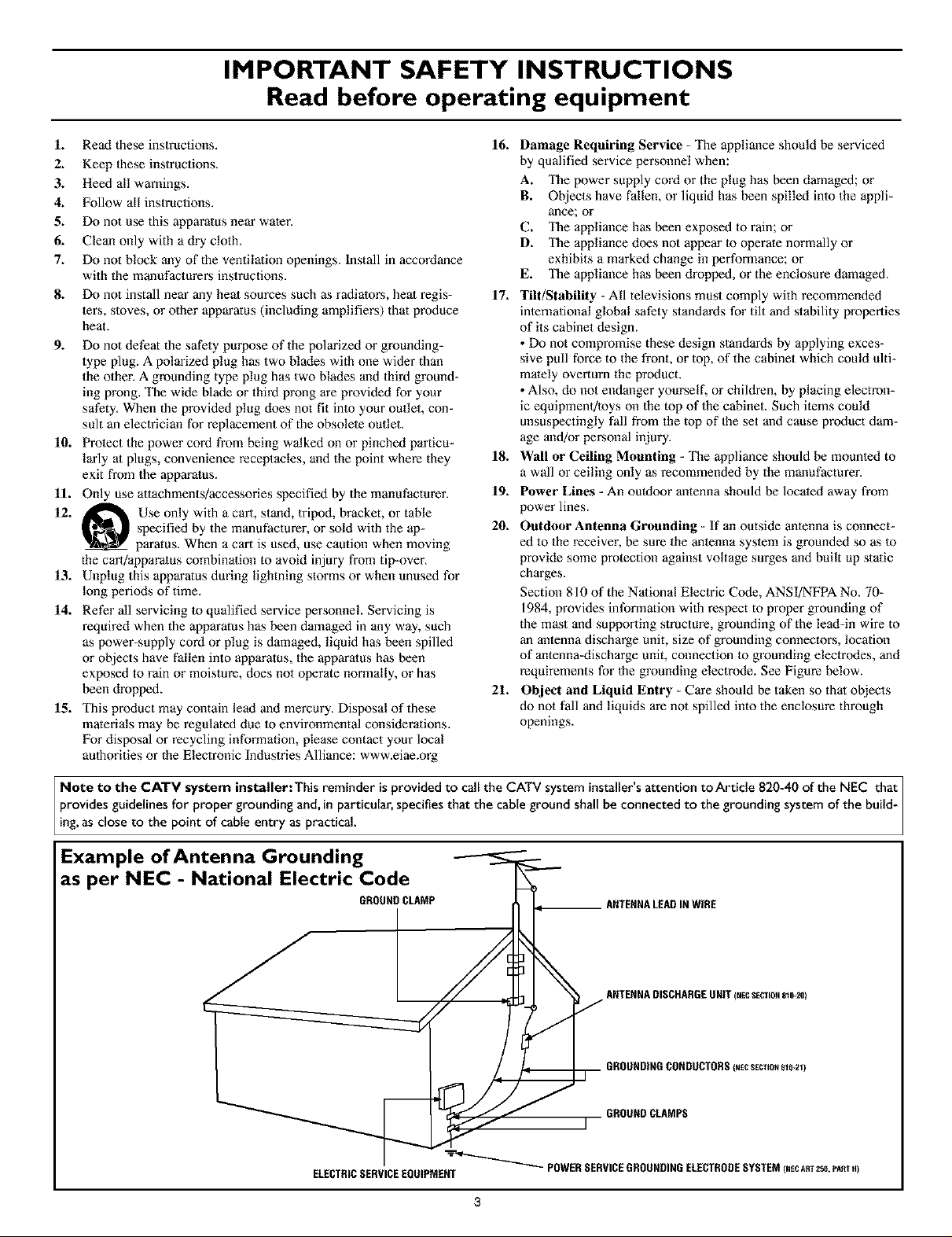
20. Outdoor Antenna Grounding - If an outside antenna is connect-
21. Object and Liquid Entry - Care should be taken so that objects
Damage Requiring Service - The appliance should be serviced
by qualified service personnel when:
A. The power supply cord or the plug has been damaged; or
B. Objects have fallen, or liquid has been spilled into the appli-
ance; or
C. The appliance has been exposed to rain; or
D. The appliance does not appear m operate normally or
exhibits a marked change in performance; or
E. The appliance has been dropped, or the enclosure damaged.
international global safety standards for tilt and stability properties
of its cabinet design.
• Do not compromise these design standards by applying exces-
sive pull force to the front, or top, of the cabinet which could ulti-
mately overturn lhe product.
• Also, do not endanger yourself, or children, by placing electron-
ic equipmenffloys on the top of the cabinet. Such items could
unsuspectingly fall from the top of the set and cause product dam-
age and/or personal injury.
a wall or ceiling only as recommended by the manufacturer.
power lines.
ed to the receiver, be sure the antenna system is grounded so as to
provide some protection against voltage surges and built up static
charges.
Section 810 of the National Electric Code, ANSI/NFPA No. 70-
1984, provides information with respect to proper grounding of
the mast and supporting structure, grounding of the lead-in wire to
an antenna discharge unit, size of grounding connectors, location
of antenna-discharge unit, connection to grounding electrodes, and
requirements for the grounding electrode. See Figure below.
do not fall and liquids are not spilled into the enclosure through
openings.
Note to the CATV system installer: This reminder isprovided to call the CATV system installer'sattention to Article 820-40 of the NEC that i
provides guidelines for proper grounding and, in particular, specifiesthat the cable ground shall be connected to the grounding system of the build-
ing,as c ose to the point of cabe entry as practica.
Example of Antenna Grounding
as per NEC - National Electric Code
GROUNDCLAMP
ELECTRICSERVICEEQUIPMENT
POWERSERVICEGROUNDINGELECTRODESYSTEMINECART258,PA_TH)
ANTENNALEADINWIRE
INTRODUCTION
Welcome/Registration of Your TV ................. 2
Safety/Precautions .............................. 2-3
Features ........................................ 5
_ CONNECTING ACCESSORYDEVICES
TO YOUR TV
InformationaboutTV Signals ........................ 6
Descriptions ofJacks,Cables,and Connectors ........... 7
PanelJackCompatibility Information .................. B
Pre-connectionRecommendations ................... 9
Connecting aVCR ............................... 10
Connecting aVCR and Cable Box ................... 11
Connecting an S-VideoDevice ..................... 12
Connecting a StandardDVD Player .................. 13
Connecting a Progressive-scanDVD Player ............ 14
Connecting an HD SatelliteReceivertoYPbPr ......... 15
Connecting an HD SatelliteReceiver to DVI ........... 16
Connecting SurroundSoundEquipment .............. 17
Connecting to the SideInputs:VideoGameSystem...... 18
Labelingthe Audio/Video InputSources............... 19
USING THE REMOTE CONTROL
Programming the Remote Control ................ 20-21
[]Setup Codes for Accessory Devices ......... 22-23
Using the TV Remote'sVCR-specific Buttons ..... 24
UsingActive Control TM Plus ....................... 25
Using the Zoom Control .......................... 26
USING THE ON-SCREEN MENUS
PICTURE
Adjusting/Setting the Picture Controls ................ 27
Setting the TV for Stereo Programming ............... 41
Turning theAVL (Audio Volume Leveler) on or off ...... 42
Adjusting the DeltaVotume ........................ 43
Selecting anAutoSound TM Option ................... 44
FEATURES
Using Closed Captioning .......................... 45
_ Setting the Sleeptimer ...................... 46
Setting the On Timer ....................... 47
CHANNELS
Using the Channel List............................ 48
[_ Removing Channelsfrom the Channel List ....... 49
Using Lock Channel ........................ 50
Using Lock After ................................ 51
Blocking Programming Basedon TV Ratings ........... 52
Blocking Programming Basedon Movie Ratings ......... 53
Turning the Antenna Attenuator on or off ............. 54
GENERAL
Turning the Menu Background on or off .............. 55
[]Using Surf ................................ 56
Using Dual Screen and PIP.................... 57
ChangingChannels or Input Sources in Dual Screen/PIP . .58
Selecting a Picture Freeze Option ................... 59
Resetting the Audio/Video Settingsto Factory
DefaultValues ................................. 60
Selecting an On-screen DisplayOption ............... 61
Selecting aTime Zone and Setting the Daylight
SavingsControl ................................ 62
Setting up or Changinga PIN (Personal
Identification Number) .......................... 63
Setting the Subwoofer Control ..................... 64
[]Selecting a Digital Processing Option ......... 28
Selecting a Dynamic Contrast Option ........ 29
Selecting a DNR (Dynamic Noise Reduction) Option . .30
Turning on Color Enhancement ..................... 31
Selecting an AutoPicture TM Option .................. 32
Selecting a Picture Format Option ................ 33-34
SOUND
Adjusting the TV and Headphone Volume ............. 35
_ Selecting aTV Equalizer Option ............... 36
Adjusting TV Speaker Balance ................. 37
Turning Loudness on or off ........................ 38
Selecting a Sound Mode Option .................... 39
Using Alternate Audio (SAP) ....................... 40
ADDITIONAL INFORMATION
Cleaning the TV ................................. 65
Cleaning or Replacingthe Filters ............ 66-67
Replacingthe Lamp ...................... 68-69
Resetting the Lamp'sLifetime Counter ............... 70
Troubleshooting .............................. 71-72
Product Specifications ............................ 73
Index ......................................... 74
Factory Service Locations ...................... 75-76
Limited Warranty ................................ 78
4
Compact design with low weight
The unique Philips single-panel liquid-crystal-on-silicon (LCOS)
technology allows for a large screen TV with a very low depth
and low weight. This TV will find a place in any living room
without occupying a large area, and it can be easily handled by
two persons.
Philips Single-panel, LCOS Imaging System
The Philips single-panel LCOS technology produces unmatched
high-resolution and flicker-free video with superb brightness.
This technology enables a large-screen-size TV with low weight
and shallow depth without any concerns for convergence or
image retention.
Digital Natural Motion TM
Digital Natural Motioff rMoffers razor-sharp reproduction of
movement and motion. Its unique and highly advanced process-
ing calculates motion trajectories of moving picture elements. It
corrects jerky movement from both studio programs or movie
material.
Digital CrystalClear TM
Digital CrystalClear'rM--with Dynamic Contrast, comb filter,
9-bit processing, luminance enhancements, and color enhance-
merits---offers a crisp and natural picture from any type or quali-
ty of source. The comb filter supports the picture demands of
DVD players and other advanced high-resolution video sources.
Active Control TM Plus+
Active Conlrof rM Plus+ atttomatically analyzes the incoming sig-
nals from the Tuner, AV 1, AV2, and Side video inputs 50 times
per second and adjusts key picture settings. In addition to meas-
uring picture noise, this feature uses an ambient light sensor to
Miust the picture settings accor_fing to viewing conditions in the
room.
Dolby* Virtual Surround
Dolby processing circuitry provides an enhanced cinema sur-
round sound effect without the need for rear speakers.
Double-window, Two-Tuner PIP
Your TV features double-window, two-ttmer PIP with second
tuner double window. The TV also has single PIP (free position-
ing), as well as threefold and sixfold side PIPs. In addition, you
get photo finish, freeze Main, and freeze PIR Replay lets you
play back the previous few seconds in a PIP screen--if you
missed the action, replay it as much as you want.
Audio/Video (A/V) Jack Panel
The A/V jack panel allows direct connections with VCRs,
DVDs, high-definition receivers, or other devices, provirfing
quality TV picture and sound playback.
AudioVolume Leveler (AVL) Control
AVL keeps the TV sound at an even level. Peaks and valleys that
occur at commercial breaks or during program changes are
reduced, provkfing a more consistent, comfortable sound.
V-Chip (with Channel Lock)
The V-Chip feature (with Channel Lock) will allow you to block
the viewing of channels or programs with certain ratings, and thus
prevent your children from watching inappropriate materials.
Autoprogramming
The TV's Autoprogram feature scans (when activated) for all
available channels from regular antenna or cable signals and
stores active broadcast stations in the TV's memory.
Surf Button
Philips Auto Surf rMallows you to easily switch between only the
channels lhat are of interest to you. Surf allows two-channel
surfing or nine-channel surfing.
As you unpack your TV, please note the included items:
• Quick Use and Setup Guide to help you set up your new TV.
• Directions]br Use manual--contains information on safety,
set maintenance, Factory Service Center locations, and prod-
uct warranty
• Warranty Registration Card
• Remote Control (with supplied batteries).
Please take a few minutes to complete your registration card.
The serial number for the TV is on the rear of the set. For
your future reference, please write down the serial and
model number of this television in the space provided on the
warranty page at the back of this manual. (In the unlikely
event you should need to place a service call, these numbers
will be needed.)
Your new television and its packing contain materials that can
be recycled and reused. Specialized companies can recycle
your product to increase the amount of reusable materials and
minimize the amounts that need to be properly disposed of.
Your product also uses batteries that should not be thrown
away when depleted, but should be handed in and disposed of
as small chemical waste.
When you replace your existing equipment, please find out
about the local regulations regarding disposal of your old tel-
evision, batteries, and packing materials.
Star_ Partner, Consumer
_As an Energy Philips
Energy Star_ is a U.S. registered mark, Using products with the
Energy Star_ label can save energy. Saving energy reduces air pol-
lution and lowers utility bills.
*Manufactured under license from Dolby Laboratories. "Dolby" and
the double-D symbol are trademarks of Dolby Laboratories.
Active Conlrol, AutoPicture, AutoSound, AutoSurf, Cineos, Digital
Crystal Clear, Digital Natural Motion, and Pixel Plus are trademarks
of Philips Consumer Eleclronics. Copyright 2003 Philips Consumer
Electronics. All rights reserved.
Electronics has determined this product meets the
Energy Star® guidelines for energy efficiency.
5

Over the Air
Analog
Signal
Digital
Signal
Satellite Sa_llites
TV
Antenna
atYour
Home
Cable
Cable TV
Company
[
S_elliteTV
Compa_
Satellite
Dish
Home
Telephone Line
CableTV Signal(Analog)
Satellite
Receiver
atYour
Home
For Direct Connection
toYour TV or to a
Cable Box,VCR, or
Satellite Receiver
Your High-definition-ready Set
m
High-definition television offers a picture with unprecedented crispness and clarity. The TV broadcast industry is moving toward high definition as
the signal standard. Currently, the number of programs being broadcast in high definition is limited, but this is changing. To view high-definition plograms on
your TV, you will need to connect a satellite receiver, cable box, or set-top box that can decode HD signals.
6
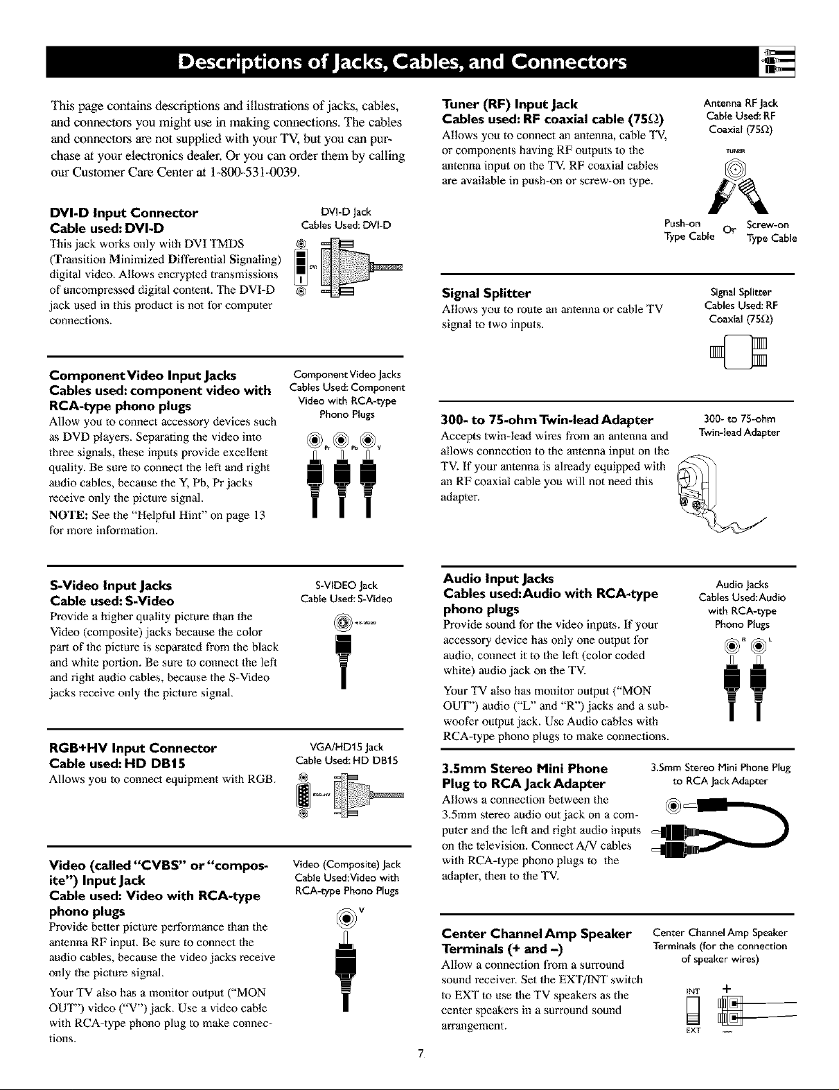
This page contains descriptions and illustrations of jacks, cables,
and connectors you might use in making connections, The cables
and connectors are not supplied with your TV, but you can pur-
chase at your electronics dealer. Or you can order them by calling
our Customer Care Center at 1-800-531-0039.
Tuner (RF) Input Jack
Cables used: RF coaxial cable (75_)
Allows you to connect an antenna, cable TV,
or components having RF outputs to the
antenna input on the TV. RF coaxial cables
are available in push-on or screw-on type.
Antenna RFJack
Cable Used:RF
Coaxial (75D)
DVI-D Input Connector
Cable used: DVI-D
This jack works only with DVI TMDS
(Transition Minimized Differential Signaling)
digital video, Allows encrypted transmissions
of uncompressed digital conlent. The DVI-D
jack used in this product is not for computer
connections.
Component Video Input Jacks
Cables used: component video with
RCA-type phono plugs
Allow you to connect accessory devices such
DVI-D Jack
Cables Used: DVI-D
Component Video Jacks
Cnbles Used: Component
Video with RCA-type
Phono Plugs
as DVD players. Separating the video into
three signals, these inputs provide excellent
quality. Be sure to connect the left and right
audio cables, because the Y, Pb, Pr jacks
receive only lhe picture signal.
NOTE: See the "Helpful Hint" on page 13
for more information.
S-Video Input Jacks
Cable used: S-Video
Provide a higher quality picture than 1he
Video (composile) jacks because the color
part of the picture is separaled from the black
and while portion. Be sure to connect 1he left
and right audio cables, because the S-Video
jacks receive only the picture signal.
S-VIDEO Jack
Cable Used: S-Video
T
RGB+HV Input Connector VGA/HD15Jack
Cable used: HD DBt5 CaNeUsed:HD DB1S
Allows you to connect equipment with RGB.
Video (called "CVBS" or"compos-
ite") Input Jack
Cable used: Video with RCA-type
Video (Composite) Jack
Cable Used:Video with
RCA-type Phono Plugs
phono plugs
Provide better picture performance than the
antenna RF input. Be sure to connect the
audio cables, because the video jacks receive
only the picture signal.
Your TV also has a monitor output ("MON
OUT") video ("V') jack. Use a video cable
with RCA-type phono plug to make connec-
tions.
Push-on Or Screw-on
Type Cable Type Cable
Signal Splitter
Allows you to mule an antenna or cable TV
signal to two inputs.
300- to 75-ohm Twin-lead Adapter
Accepts twin-lead wires from an antenna and
allows connection to the antenna input on the
TV. If your antenna is already equipped with
an RF coaxial cable you will not need 1his
adapter.
Audio Input Jacks
Cables used:Audio with RCA-type
phono plugs
Provide sound for the video inputs. If your
Signal Splitter
Cables Used: RF
Coaxial (75£_)
300- to 75-ohm
Twin-lead Adapter
Audio Jacks
C_bles Used:Audio
with RCA-type
Phono Plugs
accessory device has only one oulput for
audio, connect it to the left (color coded
while) audio jack on the TV.
Your TV also has monitor oulput ("MON
OUT") audio ("L" and "R") jacks and a sub-
woofer output jack. Use Audio cables with
RCA-type phono plugs to make connections.
3.Smm Stereo Mini Phone 3.5ram Stereo Mini Phone Plug
Plug to RCA Jack Adapter to RCA JackAdapter
Allows a connection between the _h _L._.._
3.5mm stereo audio out jack on a com-
puter and the left and right audio inputs
on the television. Connect A/V cables
with RCA-type phono plugs m the
adapter, then to the TV.
Center Channel Amp Speaker
Terminals (+ and -)
Allow a connection from a SUlTOUnd
sound receiver. Set the EXT/INT switch
to EXT to use the TV speakers as the
cenler speakers in a surround sound
arrangement.
Center Channel Amp Speaker
Terminals (for the connection
of speaker wires)
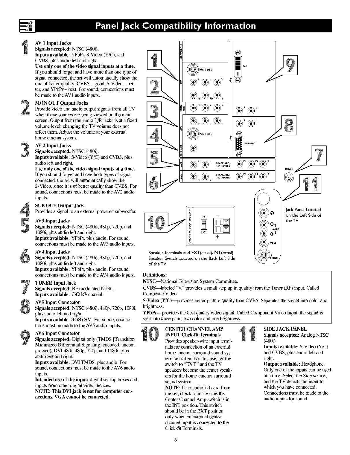
AV 1 Input Jacks
Signals accepted: NTSC (4800.
Inputs available: YPbPr, S-Video (Y/C), and
CVBS, plus audio left and right.
Use only one of the video signal inputs at a time.
If you should forget and have more than one type of
signal connected, the set will automatically show the
one of better quality: CVBS--good, S-Video--bet-
ter, and YPbPr--best. For sound, connections must
be made to the AVI audio inputs.
MON OUT Output Jacks
2
Provide video and audio output signals from all TV
when those sources are being viewed on the main
screen. Output from the audio L_ jacks is at a fixed
vc;lume level; changing the TV volume does not
_ect them. Adjust the volume at your external
home cinema system.
AV 2 Input Jacks
Signals accepted: NTSC (480i),
3
Inputs available: S-Video (Y/C) and CVBS, plus
audio left and right.
Use only one of the video signal inputs at a time.
If you should forget and have both types of signal
connected, the set will automatically show the
S-Video, since it is of better quality than CVBS. For
sound, connections must be made to the AV2 audio
inputs.
SUB OUT Output Jack
Provides a signal to an external powered subwoofer.
4
AV3 Input Jacks
Signals accepted: NTSC (4800, 480p, 720p, and
1080i, plus audio left and right.
Inputs available: YPbPr, plus audio. For sound,
connections must be made to the AV3 audio inputs.
AV4 Input Jacks
Signals accepted: NTSC (4800, 480p, 720p, and
1080i, plus audio left and right.
Inputs available: YPbPr, plus audio. For sound,
connections must be made to the AV4 audio inputs.
TUNER Input Jack
Signals accepted: RF modulated NTSC.
Inputs available: 75_ RF coaxial.
AV5 Input Connector
Signals accepted: NTSC (4800, 480p, 720p, I080i,
plus audio left and right.
Inputs available: RGB+HV. For sound, connec-
tions must be made to the AV5 audio inputs.
AV6 Input Connector
Signals accepted: Digital only (TMDS [Transition
Minimized Differential Signaling] encoded, uncom-
pressed); DVI 480i, 481_p, 720p, and 1080i, plus
audio left and right.
Inputs available: DVI TMDS, plus audio. For
sound, connections must be made to the AV6 audio
inputs.
Intended use of the input: digital set-top boxes and
inputs from other digital video devices.
NOTE: This DVI jack is not for computer con-
nections. VGA cannot be connected.
llllll _1
I
®
@
((e)) Ilq
EXT
+
SpeakerTerminals and EXT(ernal)/INT(ernal)
SpeakerSwitch Located on the Back Left Side
of the TV
Definitions:
NTSC--National Television System Committee.
CVBS--labeled "V," provides a small step up in quality from the "t_ner (RF) input. Called
Composite Video.
S-Video (Y/C)--provides better picture quality than CVBS. Separates the signal into color and
brightness.
YPbPr-_rovides the best quality video signal. Called Component Video Input, the signal is
split into three paris, two color and one brightness.
CENTER CHANNEL AMP
INPUT Click-fit Terminals
Provides speaker-wire input termi-
nals for connection of an external
home-cioema surround-sound sys-
tem amplifier. For Ihis use, set the
switch to "EX'I;" and the "IV
speakers become the center speak-
ers for the home-cinema surround-
sound system.
NOTE: If no audio is heard from
the set, check to make sure the
Center Channel Amp switch is in
the tNT position. This switch
should be in the EXT position
only when an external center
channel input is connected to the
Click-fit Terminals.
((e))l
tklI) ) Ivim
SIDE JACK PANEL
Signals accepted: Analog NTSC
(4800.
Inputs available: S-Video (Y/C)
and CVBS, plus audio left and
right.
Output available: Headphone.
Only one of the inputs can be used
at a time. Select the Side source,
and Ihe 'IV detects the input to
which you have connected.
Connections must be made to the
audio inputs for sound.
on the Left Side of
the TV
8

Positioning the TV
Before connecting accessory devices--VCR,
DVD player, or HD satellite receiver, for exam-
pie--please keep the following in mind:
• Place the TV on a flal surface. An unlevel sur-
face may adversely affect picture pertormance.
• Do not place the TV on shag carpet or any sur-
face that will block the ventilation openings at
the Ix)ttom of the set. Blockage will cause the
TV to overheat and shut down.
• Allow 4 to 6 inches of space behind the TV
for ventilation.
• An optional swivel and an optional stand are
available for use with your TV. See your elec-
tronics dealer.
• Test various locations in the room to find the
optimal spot to locate the set for best viewing.
• Do not place the TV in direct sunlight or near
a heating appliance.
• Do not expose the TV to rain or moisture.
• To prevent any unsafe situations, do not place
objects on top of the TV.
Providing Protection Against Power
Surges
• Connect all accessory devices before you plug
any of their power cords into the wall outlet or
power strip. NEVER plug your TV into an
outlet that is controlled by a wall switch.
• Turn off the TV and/or accessory devices
betore you connect or disconnect any cables.
• Ensure that all antennas and cables are proper-
ly grounded. See page 3, "Important Safety
Instructions."
Protecting Accessory Devices from
Overheating
• Arrange accessory devices so that air can cir-
culate freely around them.
• Don't stack the accessory devices. Arrange
them to allow tor good ventilation. The
optional Philips stand provides enough room
for two accessory devices, side by side.
• If you connect an audio receiver or amplifier,
place it on the top shelf so the heated air from
it will not flow around other components.
Connecting Cables
Be sure to insert each cable firmly into Ihe cor-
rect jack.
Using the Connection Examples in
This Manual
The accessory device jack panels shown are fur
example purpose only. The jack panels on your
accessory devices may look difterent. Also, note
that connections can be made in various ways.
The examples are presented only as guides.
For safety, do not
set objects on top
of the TV,
Place the TV on
a flat surface,--------_
Optional
Optional Stand
it will not be exposed
to heat or moisture.
_ Situate the TV where
X
Allow 4 to 6 inches
behind the TV for
venti|alion.
Do not place 1he TV on a surface that will block
1he air filters localed underneath the set,
9
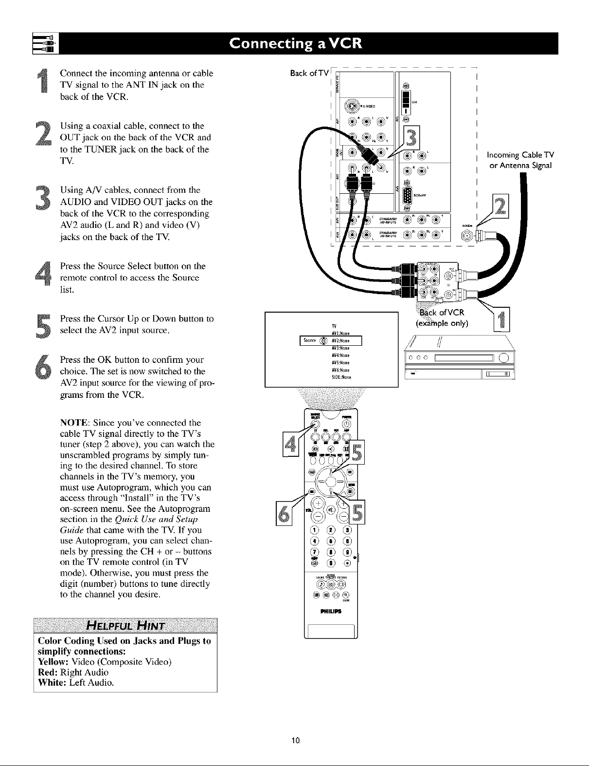
Connecttheincomingantennaorcable
TVsignaltotheANTINjackonthe
backoftheVCR.
Usingacoaxialcable,connecttothe
OUTjackonthebackoftheVCRand
totheTUNERjackonthebackofthe
TV.
Using A/V cables, connect from the
3
AUDIO and VIDEO OUT jacks on die
back of the VCR to the corresponding
AV2 audio (L and R) and video (V)
jacks on the back of lhe TV.
remote control to access the Source
Press the Source Select button on the
list.
Back ofTV F
®
@
IncomingCaNe TV
or Antenna Signal
Press the Cursor Up or Down button to
select the AV2 input source.
Press the OK button to confirm your
choice. The set is now swilched to the
AV2 input source for the viewing of pro-
grams from the VCR.
NOTE: Since you've connected the
cable TV signal directly to the TV's
tuner (slep 2 above), you can walch the
unscrambled programs by simply tun-
ing to the desired channel. To store
channels in the TV's memory, you
must use Autoprogram, which you can
access through "Install" in the TV's
on-screen menu. See the Autoprogram
section in the Quick Use and Setup
Guide that came with the TV. If you
use Autoprogram, you can select chan-
nels by pressing the CH + or - buttons
on the TV remote control (in TV
mode). Otherwise, you must press the
digit (number) buttons to tune directly
to the channel you desire.
N
®
MnLII_
(example only)
\
/ \
\
\
Color Coding Used on Jacks and Plugs to
simplify connections:
Yellow: Video (Composite Video)
Red: Right Audio
White: Left Audio,
10

NOTE: A cable box with AUDIO OUT jacks
such as the one used in the example on this
page might pass stereo sound to the TV. Check
with your cable TV company. The RF jack out-
put jack on a cable box (commonly labeled
"OUT TO TV," "OUTPUT," or "OUT") will
not pass stereo sound to your TV.
Connect the incoming cable TV signal
to a two-way signal splitter. The signal
splitter enables you to route the cable
signal to the TV without using the
OUT TO TV jack on the cable box,
which will not pass stereo sound to the
TV.
Using a coaxial cable, connect to one
of the connectors on the signal splitter
and to the TUNER jack on the back of
the TV.
Using a coaxial cable, connect to the
other connector on the signal splitter
and to the CABLE IN jack on the back
of the cable box.
Backof TV
Incoming
Cable TV
Signal
Splitter
Signal
Using Audio/Video cables, connect to
4
the AUDIO and VIDEO OUT jacks on
the back of the cable box and to the
corresponding AUDIO and VIDEO IN
jacks on the back of the VCR.
Using Audio/Video cables, connect to
the AUDIO and VIDEO OUT jacks on
the back of the VCR and to the corre-
sponding AV2 audio (L and R) and
video (V) input jacks on the back of
the TV.
Press the Source Select button on the
remote control to access the Source
list.
Press the Cursor Up or Down button to
select the AV2 input source.
Press the OK button to confirm your
choice. The set is now switched to the
AV2 input source for the viewing of pro-
grams from the cable box or the VCR.
Color Coding Used on ,lacks and Plugs to
simplify connections:
Yellow: Video (Composite Video)
Red: Right Audio
White: Left Audio.
O00 [
NOTE: Since you've connected the
cable TV signal directly to the TV's
tuner (step 2 above), you can watch
the unscrambled programs by sim-
ply tuning to the desired channel. To
store channels in the TV's memory,
you must use Autoprogram, which
you can access through "Install" in
the TV's on-screen menu. See the
Autoprogram section in the Quick
Use and Setup Guide that came with
the TV. If you use Autoprogram,
you can select channels by pressing
the CH + or - buttons on the TV
remote control (in TV mode).
Otherwise, you must press the digit
(number) buttons to tune directly to
the channel you desire.
11

UsinganS-Videocable,connecttothe
S-Videooutputonthebackofthe
S-VideodeviceandtotheAV2S-
VIDEOinput.
UsingStereoAudiocables,connectto
theAUDIOOUTjacksonthebackof
theS-Videodeviceandtothecorre-
spondingAV2audioinputs(LandR).
PresstheSourceSelectbuttononthe
remotecontroltoaccesstheSource
list.
Press the Cursor Up or Down button to
select the AV2 input source.
Press the OK button to confirm your
choice. The set is now switched to the
AV2 input source for the viewing of pro-
grams from the S-Video device.
ii!!i!ii!iiiil iiil¸i+iiii!i¸ii!i ,i
To simplify making connections, the connec-
tors on audio and video cables are often color
coded lo match the colors on TV jacks, red for
right, and white for left.
Back ofTVF
I
I
I
I
I
m
Back
only)
\
\
\
000 I
I _
II
J
PHIMPS
12
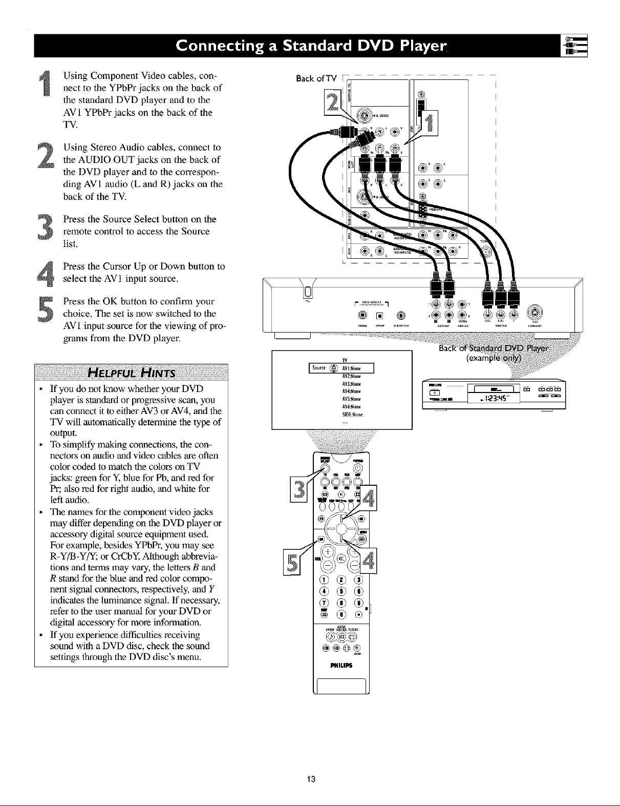
Using Component Video cables, con-
nect to the YPbPr jacks on the back of
the standard DVD player and to the
AV 1 YPbPr jacks on the back of the
TV.
Using Stereo Audio cables, connect to
2
the AUDIO OUT jacks on the back of
the DVD player and to the correspon-
ding AV 1 audio (L and R) jacks on the
back of the TV.
Press the Source Select button on the
remote control to access the Source
3
list,
Press the Cursor Up or Down button to
4
select the AVI input source.
Press the OK button to confirm your
choice, The set is now swilched to the
AVI input source for the viewing of pro-
grams from the DVD player.
Back ofTV
® [] ®
ii!!i!ii!iiiil,ii il¸iiii ii!i¸ii!i¸iiiiii!i ii!ili)ii!i iiiiii!i ii!iliN i ili!i!!ii i i i!ii ii!!ilil¸!iii!!iii ;i!iiiil¸ii!ili)ii!i iiiiii!i ii!ili!i ii!iiii!i¸ii
• If you do not know whether your DVD
player is standard or progressive scan, you
can connect it to either AV3 or AV4, and the
TV will automaJically determine the lype of
output,
• To simplify making connections, the con-
nectors on audio and video cables are often
color coded to match lhe colors on TV
jacks: green for Y, blue for Pb, and red for
Pr; also red for right audio, and white for
left audio.
• The names for the component video jacks
may differ depending on the DVD player or
accessory digital source equipment used,
For example, besides YPbPr, you may see
R-Y/B-Y/Y; or CrCbY, Although abbrevia-
lions and terms may vary, the letters B and
R stand for the blue and red color compo-
nent signal connectors, respectively, and Y
indicates the luminance signal, If necessary,
refer to the user manual for your DVD or
digital accessory for more information.
• If you experience difficulties receiving
sound with a DVD disc, check the sound
settings through the DVD disc's menu.
lV2:H_ne
lV3:H_ne
lV4:H_ne
lV_:H_ne
AV6:None
SlOE:None
2q: ?
®
13
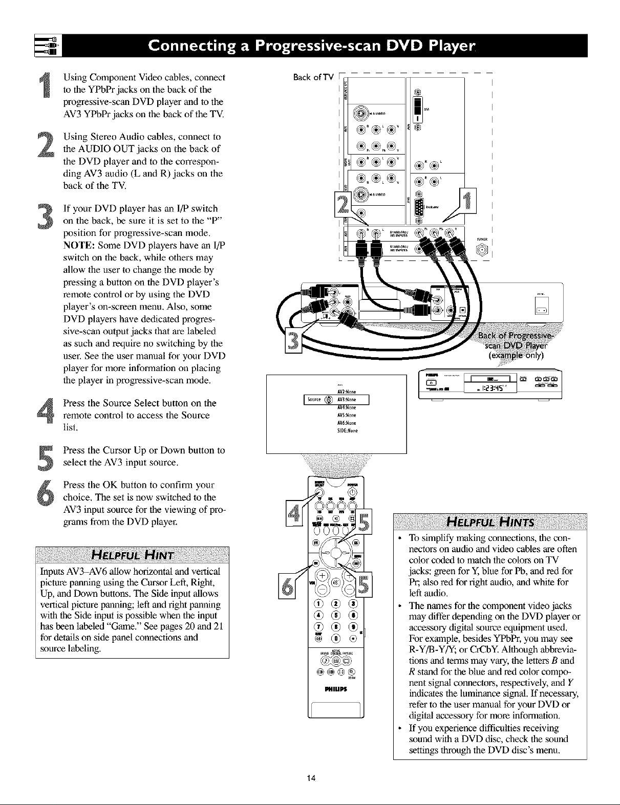
Using Component Video cables, connect
to the YPbPr jacks on the back of the
progressive-scan DVD player and to the
AV3 YPbPr jacks on the back of the TV.
Using Stereo Audio cables, connect to
2
the AUDIO OUT jacks on the back of
the DVD player and to the correspon-
ding AV3 audio (L and R) jacks on the
back of the TV.
If your DVD player has an I/P switch
3
on the back, be sure it is set to the "P"
position for progressive-scan mode.
NOTE: Some DVD players have an I/P
switch on the back, while others may
allow the user to change the mode by
pressing a button on the DVD player's
remote control or by using the DVD
player's on-screen menu. Also, some
DVD players have dedicated progres-
sive-scan output jacks that are labeled
as such and require no switching by the
user. See the user manual for your DVD
player for more information on placing
the player in progressive-scan mode.
Back ofTV F
Press the Source Select button on theremote control to access the Source
list.
Press the Cursor Up or Down button to
select the AV3 input source.
Press the OK button to confirm your
choice, The set is now switched lo the
AV3 input source for the viewing of pro-
grams from the DVD player,
iii iill¸i!iiii!ilJiiiiii!i!ill¸ IJiiiiiii!iiiii!ii!iii iiii:! i¸i!ii!iiii!!ill¸ii¸!iiiiiiiii!!N ! !:ii!i!Ni i ii!!i i!iii!i i¸i!ii!iiii!!i :!!;ii!ii!iiii!!ill¸ii¸!iiiiiii!i!i!iiii!!ill¸ii¸!iiiiiii!i!i!iiii!!ii
Inputs AV3-AV6 allow horizontal and vertical
picture panning using the Cursor Left, Right,
Up, and Down buttons. The Side input allows
vertical picture panning; left and right panning
with the Side input is possible when the input
has been labeled "Game," See pages 20 and 21
for details on side panel connections and
source labeling.
®
II#ILI_S
To simplify making connections, the con-
nectors on audio and video cables are often
color coded to match the colors on TV
jacks: green for Y, blue for Pb, and red for
Pr; also red for right audio, and white for
left audio.
The names for the component video jacks
may differ depending on the DVD player or
accessory digital source equipment used,
For example, besides YPbPr, you may see
R-Y/B-Y/_, or CrCbY, Although abbrevia-
tions and terms may vary, the letters B and
R stand for the blue and red color compo-
nent signal cormectors, respectively, and Y
indicates the luminance signal. If necessary,
refer to the user manual for your DVD or
digital accessory for more informalion.
If you experience difficulties receiving
sound with a DVD disc, check the sound
sethngs through the DVD disc's menu.
14
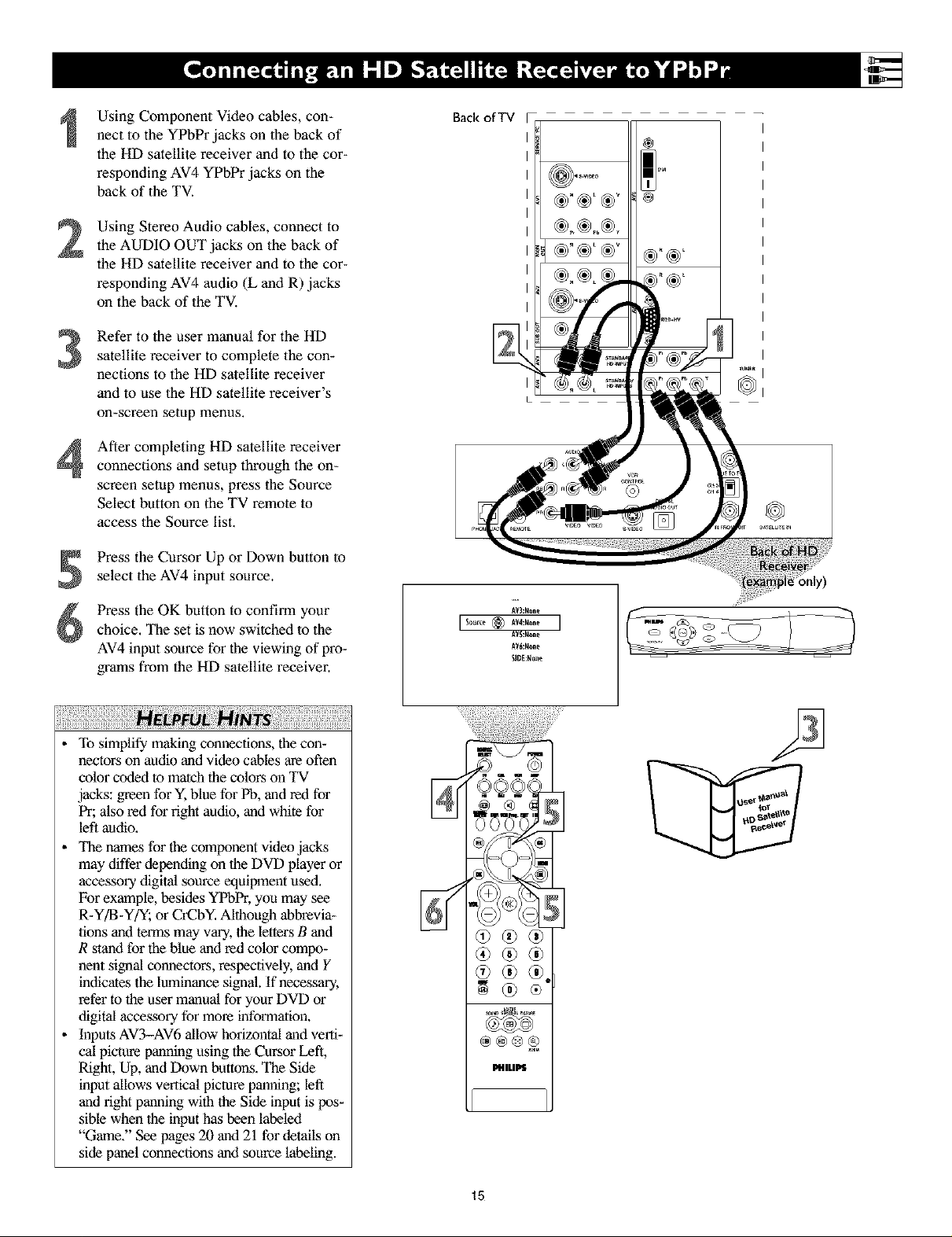
Using Component Video cables, con-
nect to the YPbPr jacks on the back of
the HD satellite receiver and to the cor-
responding AV4 YPbPr jacks on the
back of the TV.
Using Stereo Audio cables, connect to
2
the AUDIO OUT jacks on the back of
the HD satellite receiver and to the cor-
responding AV4 audio (L and R) jacks
on the back of the TV.
Refer to the user manual for the HD
3
satellite receiver to complete the con-
nections to the HD satellite receiver
and to use the HD satellite receiver's
on-screen setup menus.
After completing HD satellite receiver
4
connections and setup through the on-
screen setup menus, press the Source
Select button on the TV remote to
access the Source list.
Press the Cursor Up or Down button to
select the AV4 input source.
Backof TV
®
Press the OK button to confirm your
choice. The set is now switched to the
AV4 input source for the viewing of pro-
grams from the HD satellite receiver.
!ili i¸ii!i!iiiii!i ¸iiiiii!ii!i!i!ili!i!i!ili!i!i!ili i!i!ili i!i!ili!i!i
To simplify making connections, the con-
hectors on audio and video cables are often
color cotlex.tto match the colors on TV
jacks: green for Y, blue for Pb, and rexl for
Pr; also red for right audio, and white for
left audio,
_llaenames for the component video jacks
may differ depending on the DVD player or
accessory digital source equipment used,
For example, besides YPbPr, you may see
R-Y/B-Y/Y; or CrCbY, Although abbrevia-
tions anti terms may vary, the letters B and
R stand for the blue and red color compo-
nent signal cormectors, respectively, and Y
intricates the luminance signal. If necessary,
refer to the user manual for your DVD or
digital accessory for more informalion.
Inputs AV3-AV6 allow horizontal and verti-
cal picture panning using the Cursor Left,
Right, Up, and Down buttons. The Side
input allows vertical picture panning; left
and right panning with the Side input is pos-
sible when the input has been labeled
"Game." See pages 20 and 21 for details on
side panel connections and source labeling.
®®®
®
PfllLIPS
15

Using a DVI cable, connect to the DVI
jack on the back of the HD satellite
receiver and to the corresponding AV6
DVI jack on the back of the TV.
Back ofTV
Using Stereo Audio cables, connect to
2
the AUDIO OUT jacks on the back of
the HD satellite receiver and to the
corresponding AV6 audio (L and R)
jacks on the back of the TV.
Refer to the user manual for the HD
3
satellite receiver to complete the con-
nections to the HD satellite receiver
and to use the HD satellite receiver's
on-screen setup menus.
After completing HD satellite receiver
4
connections and setup through the on-
screen setup menus, press the Source
Select button on the TV remote to
access the Source list.
Press the Cursor Up or Down button to
select the AV6 input source.
Press the OK button to confirm your
choice. The set is now switched to the
AV6 input source for the viewing of
programs from the HD satellite receiver.
®"®_I
To simplify making connections, the con-
nectors on audio cables are often color
coded lo match the colors on TV jacks: red
for fight audio, and white for left audio.
Because DVI is such new technology, the
electronics industry is still working
toward a decision on one standard.
Philips testing has determined that com-
patibility issues exist with respect to a
limited number of high-definition
receivers when they are connected to the
DVI input on this television. If you
should experience difficulties, please
contact our Customer Care Center at 1-
800-53l -0039.
Inputs AV3-AV6 allow horizontal and verti-
cal picture panning using the Cursor Left,
Right, Up, and Down buttons. The Side
input allows vertical picture panning; left
and fight panning with the Side input is
possible when the input has been labeled
"Game." See pages 20 and 21 for details on
side panel connections and source labeling.
®@
®®@
®
LIHILIPS
16

2
3
Using speaker wires, connect to the
Center Speaker oulput terminals
(+, -) on the back of the surround
sound receiver and to the correspon-
ding (+, -) CENTER CHANNEL
AMP terminals on 1he back of 1he TV.
Set the CENTER CHANNEL AMP
INPUT switch to EXT. This allows
the TV cabinet speakers to be used
as the center speakers in a surround
sound arrangement.
Using Stereo Audio cables, connect
to the MON OUT L and R jacks on
the back of the TV and to the corre-
sponding TV IN jacks on 1he back of
the receiver.
Using an Audio cable, connect to the
SUB OUT jack on the back of the
TV and to the Audio Input jack on
the back of a powered subwoofer.
Using speaker wires, connect to the
R and L Front Speakers terminals
and to the corresponding terminals
on the backs of the front speakers.
Using speaker wires, connect to the
Surround Speakers terminals (+, -)
on the back of the receiver and to the
corresponding terminals (+, -) on 1he
back of the surround speakers,
Back of'IV
Powe_d
Subwoo_r
Front
Speakers
Press the Menu button on the remote
control to display the on-screen
menu.
Press the Cursor Down button to
select "Settings."
Press the Cursor Right button to
select "General."
Press the Cursor Down button
repeatedly untd Subwoofer is
selected.
Press the Cursor Right or Left button
to select "Yes."
NIN
"Yes" must be activated for the Subwoofer
menu selection before the SUB OUT jack
will supply output. This is because 1he sub-
woofer's low frequencies are redirected to the
main TV speakers when "No" is selected.
_neral
Da_ight _avlng
ChangePIN
Subw_0ter N0 * Yes
Set_ng_
Lamp
tamp replaced
17
Back of Receiver
(example only)
General
Settings
Daylight saving
Cha_e PiN
S_wonfer y_s* R_
To simplify making connections,
the com]ectors on audio cables are
often color coded to match the col-
ors on TV jacks: red for right audio,
and white for left audio.
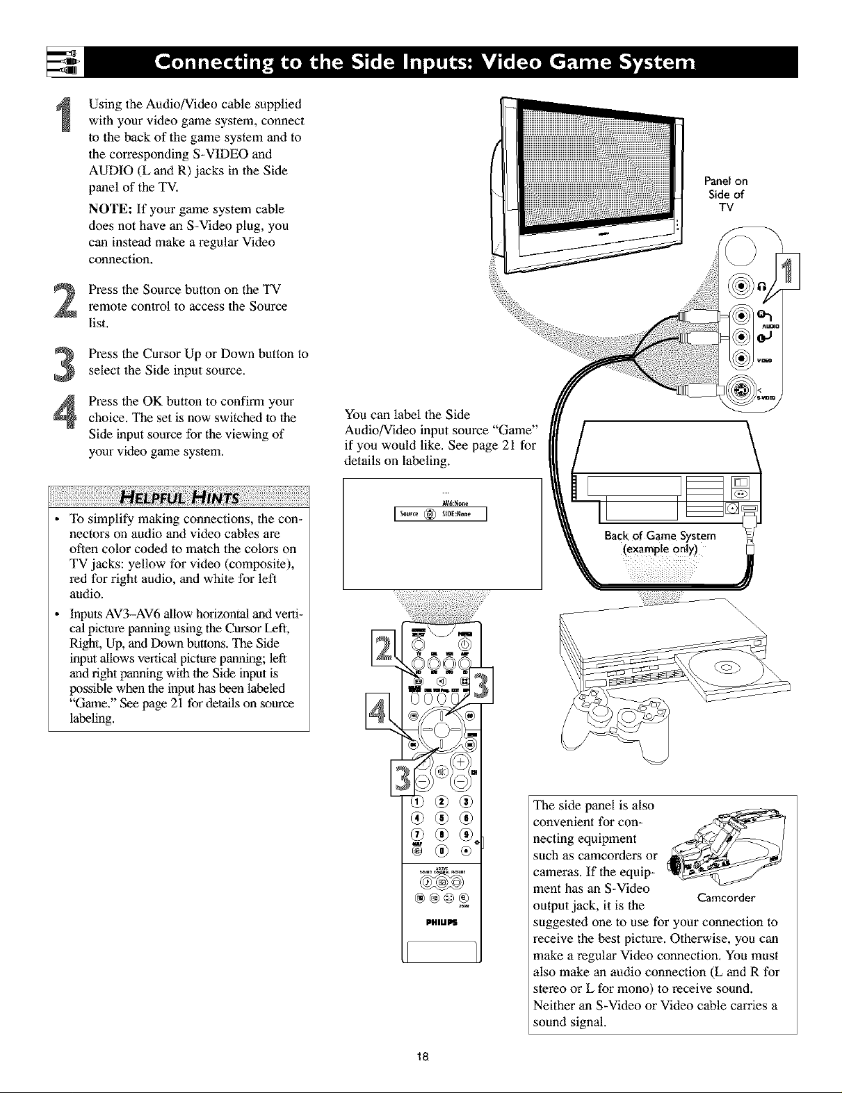
Using the Audio/Video cable supplied
with your video game system, connect
to the back of the game system and to
the corresponding S-VIDEO and
AUDIO (L and R) jacks in the Side
panel of the TV.
NOTE: If your game system cable
does not have an S-Video plug, you
can instead make a regular Video
connection.
Press the Source button on the TV
2
remote control to access the Source
list.
Press the Cursor Up or Down button to
3
select the Side input source.
Panel on
Side of
TV
Press the OK button to confirm your
4
choice. The set is now switched to the
Side input source for the viewing of
your video game system.
!ilil¸ii!i!iiiii!i¸ii!i!i!i!iiii!i!i!iiii!i!i!iiii!i!i!iiii!i!i!iiii!i!ii! i¸iiii!i ¸i!;ii¸iiil¸iiii!ii!iii!ii!iii!ii!iii!ii!iii!ii!iii!ii!i¸ii
To simplify making connections, the con-
nectors on audio and video cables are
often color coded to match the colors on
TV jacks: yellow for video (composite),
red for right audio, and white for left
audio.
Inputs AV3-AV6 allow horizontal and verti-
cal picture panning using the Cursor Left,
Right, Up, and Down buttons. The Side
input allows vertical picture panning; left
and fight panning with the Side input is
possible when the input has been labeled
"Game." See page 21 for details on source
labeling.
You can label the Side
Audio/Video input source "Game"
if you would like, See page 21 for
details on Labeling.
AV6:_one
\\\
\
®®®
PHIUPS
18
®
The side panel is also
convenient for con-
necting equipment
such as camcorders or
cameras. If the equip-
ment has an S-Video
output jack, it is the
suggested one to use for your connection to
receive the best picture. Otherwise, you can
make a regular Video connection. You must
also make an audio connection (L and R for
stereo or L for mono) to receive sound.
Neither an S-Video or Video cable carries a
sound signal.
Camcorder
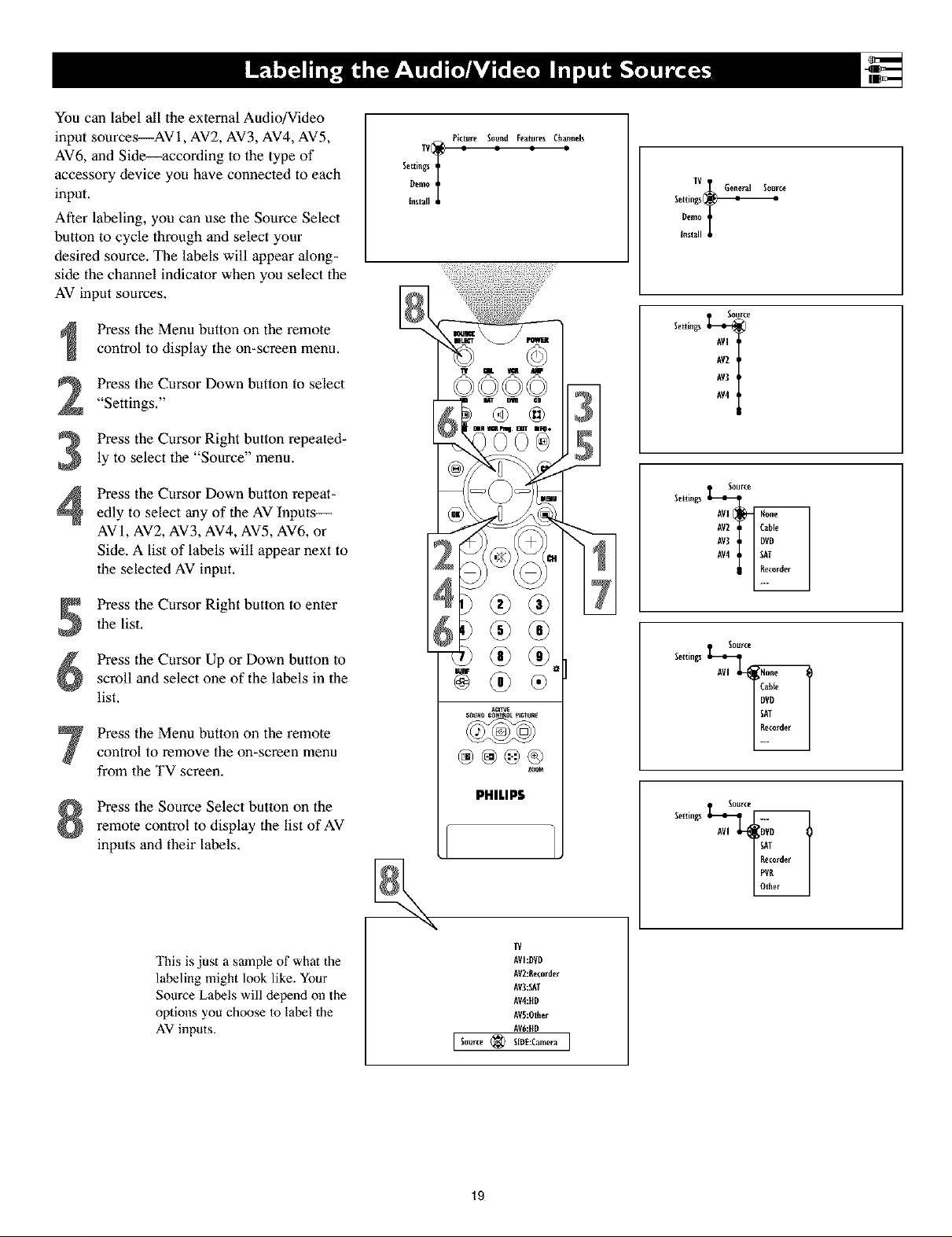
YoucanlabelalltheexternalAudio/Video
inputsources--AVi,AV2,AV3,AV4,AV5,
AV6,andSide--accordingtothetypeof
accessorydeviceyouhaveconnectedtoeach
input.
Afterlabeling,youcanusetheSourceSelect
buttontocyclethroughandselectyour
desiredsource.Thelabelswill appearalong-
sidethechannelindicalorwhenyouselectthe
AVinputsources.
PresstheMenubuttonontheremote
controltodisplaytheon-screenmenu.
PresstheCursorDownbuttontoselect
"Settings."
PresstheCursorRightbuttonrepeated-
lytoselectthe"Source"menu.
PresstheCursorDownbuttonrepeat-
edlytoselectanyoftheAVInputs--
AV1,AV2,AV3,AV4,AV5,AV6,or
Side.Alistoflabelswill appearnextto
theselectedAVinput.
Picture Sound Features Cha_nels
IV(_ = = : =
Settings
Oemo
1
Install
IV General Source
Setting_Dev,_
Install
Source
Settings _AV3AV2AVI
Source
Settings _AV3AV2AV]
PresstheCursorRightbuttontoenter
thelist.
PresstheCursorUporDownbuttonto
scrollandselectoneofthelabelsinthe
list.
PresstheMenubuttonontheremote
controltoremovetheon-screenmenu
fromtheTVscreen.
PresstheSourceSelectbuttononthe
remotecontroltodisplaythelistofAV
inputsandtheirlabels.
This is just a sample of what the
labeling might look like. Your
Source Labels will depend on the
options you choose to label the
AV inputs.
@@@@
PHILIPS
I Source _ SIDE:Can_era I
zl]w
IV
AVI:DVD
AV2:Eecorde_
AV3:SAT
AV4:ffD
AVS:Other
AV6:HD
Settings _AVI
Source
Settings
19
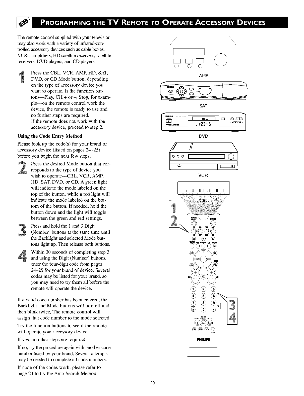
The remote control supplied with your television
may also work with a variety of infrared-con-
trolled accessory devices such as cable boxes,
VCRs, amplifiers, Hi) satellite receivers, satellite
receivers, DVD players, and CD players.
Press the CBL, VCR, AMP, HD, SAT,
DVD, or CD Mode button, depending
on the type of accessory device you
want to operate. If the function but-
tons--Play, CH + or -, Stop, for exam-
ple--on the remote control work the
device, the remote is ready to use and
no further steps are required.
If the remote does not work with the
accessory device, proceed to step 2.
Using the Code Entry Method
Please look up the code(s) for your brand of
accessory device (listed on pages 24-25)
before you begin the next few steps.
Press the desired Mode button that cor-
responds to the type of device you
wish to operate--CBL, VCR, AMP,
HD, SAT, DVD, or CD. A green light
will indicate the mode labeled on the
top of the button, while a red light will
indicate the mode labeled on the bot-
tom of the button. If needed, hold the
button down and the light will toggle
between the green and red settings.
AMP
SAT
....................L-,:23mDI ........
DVD
VGFI
Press and hold the 1 and 3 Digit
(Number) buttons at the same time until
the Backlight and selected Mode bet-
tons light up. Then release both buttons.
Within 30 seconds of completing step 3
and using the Digit (Number) buttons,
enter the four-digit code from pages
24-25 for your brand of device. Several
codes may be listed for your brand, so
you may need to try them all before the
remote will operate the device.
If a valid code number has been entered, the
Backlight and Mode buttons will turn off and
then blink twice. The remote control will
assign that code number to the mode selected.
Try the function buttons to see if the remote
will operate your accessory device.
If yes, no other steps are required.
If no, try the procedure again with another code
number listed by your brand. Several attempts
may be needed to complete all code numbers.
If none of the codes work, please refer to
page 23 to try the Auto Search Method.
2O
@®@
@@@®
PHILIPS
z_M
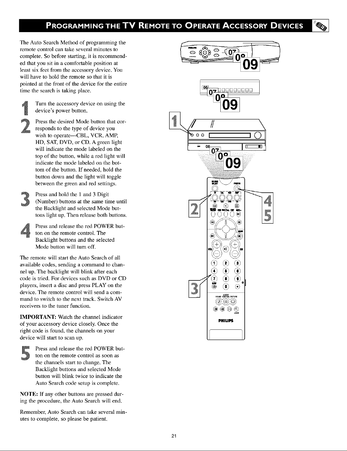
The Auto Search Method of programming the
remote control can take several minutes to
complete. So before starting, it is recommend-
ed that you sit in a comfortable position at
least six feet from the accessory device. You
will have to hold the remote so that it is
pointed at the front of the device for the entire
time the search is taking place.
Turn the accessory device on using the
device's power button,
Press the desired Mode button that cor-
2
responds to the type of device you
wish to operate--CBL, VCR, AMR
HD, SAT, DVD, or CD. A green light
will indicate the mode labeled on the
top of the button, while a red light will
indicate the mode labeled on the bot-
tom of the button. If needed, hold the
button down and the light will toggle
between the green and red settings.
Press and hold the 1 and 3 Digit
(Number) buttons at the same time until
the Backlight and selected Mode but-
tons light up. Then release both buttons.
Press and release the red POWER but-
ton on the remote control, The
Backlight buttons and the selected
Mode button will turn off.
The remote will start the Auto Search of all
available codes, sending a command to chan-
nel up. The backlight will blink after each
code is tried. For devices such as DVD or CD
players, insert a disc and press PLAY on the
device. The remote control will send a com-
mand to switch to the next track. Switch AV
receivers to the tuner function.
IMPORTANT: Watch the channel indicator
of your accessory device closely, Once the
right code is found, the channels on your
device will start to scan up.
Press and release the red POWER but-
ton on the remote control as soon as
the channels start to change. The
Backlight buttons and selected Mode
button will blink twice to indicate the
Auto Search code setup is complete,
PHILIPS
NOTE: If any other buttons are pressed dur-
ing the procedure, the Auto Search will end.
Remember, Auto Search can take several min-
utes to complete, so please be patient,
21
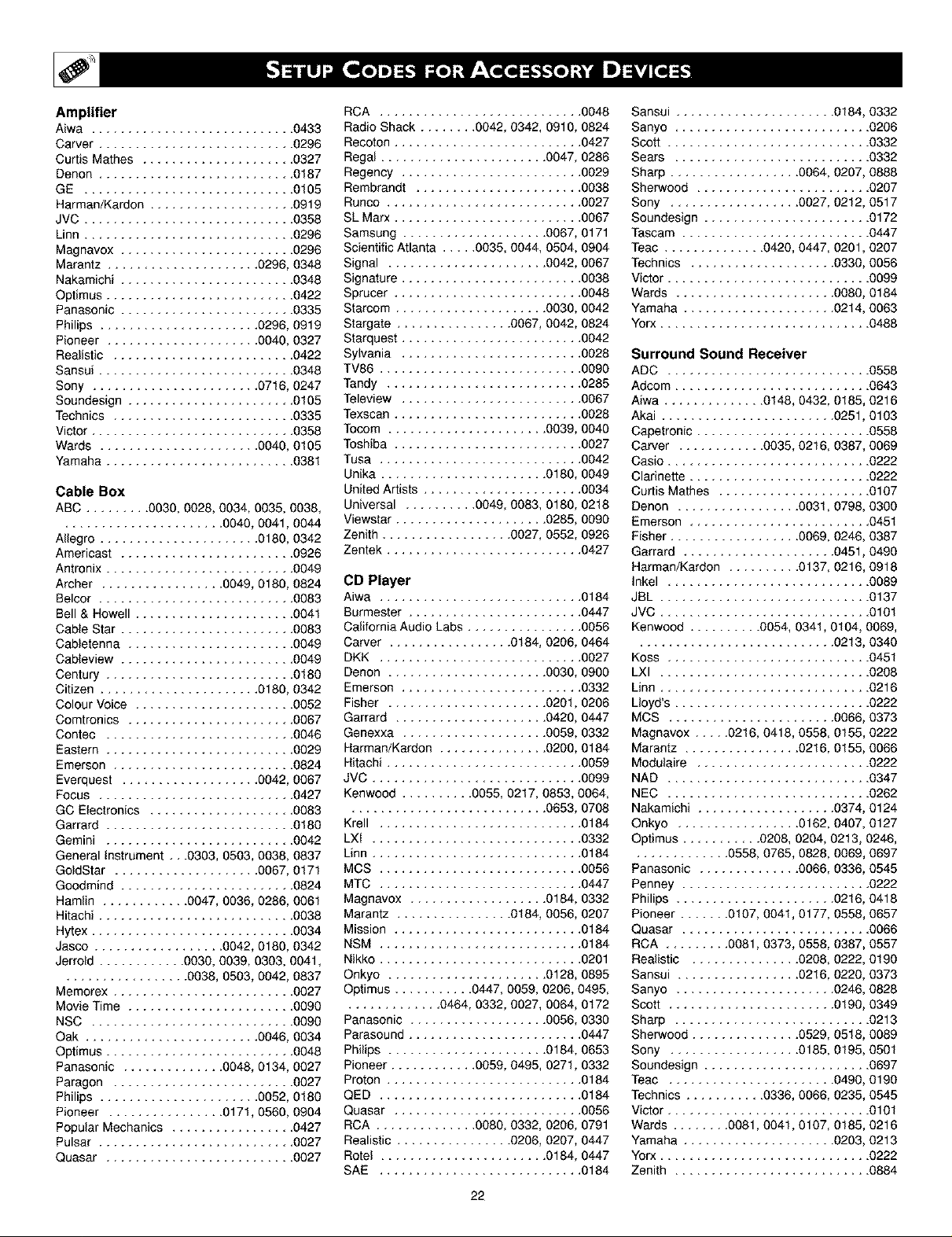
Amplifier
Aiwa ............................ 0433
Carver .............
Curtis Mathes .......
Denon .............
GE ...............
Harman/Kardon ......
JVC ...............
Linn ...............
Magnevox ..........
Marantz ..................... 0296, 0348
Nakamichi ........................ 0348
Optimus .......................... 0422
Panasonic ........................ 0335
Philips ...................... 0296, 0919
Pioneer ..................... 0040, 0327
Realistic ......................... 0422
Sansui ........................... 0348
Sony ....................... 0716, 0247
Soundesign ....................... 0105
Technics ......................... 0335
Victor ............................ 0358
Wards ...................... 0040, 0105
Yamaha .......................... 0381
Cable Box
ABC ......... 0030, 0028, 0034, 0035, 0038,
...................... 0040, 0041, 0044
Allegro ...................... 0180, 0342
Americast ........................ 0926
Antronix .......................... 0049
Archer ................. 0049, 0180, 0824
Belcor ........................... 0083
Bell & Howell ...................... 0041
Cable Star ........................ 0083
Cabletenna ....................... 0049
Cableview ........................ 0049
Century .......................... 0180
Citizen ...................... 0180, 0342
Colour Voice ...................... 0052
Comtronics ....................... 0067
Contec .......................... 0046
Eastern .......................... 0029
Emerson ......................... 0824
Everquest ................... 0042, 0067
Focus ........................... 0427
GO Electronics .................... 0083
Garrard .......................... 0180
Gemini .......................... 0042
General instrument ,, .0303, 0503, 0038, 0837
GoldStar .................... 0067, 017t
Goodmind ........................ 0824
Hamlin ............ 0047, 0036, 0286, 0061
Hitachi ........................... 0038
Hytex ............................ 0034
Jasco .................. 0042, 0180, 0342
Jerrold ............ 0030, 0039, 0303, 0041,
................. 0038, 0503, 0042, 0837
Memorex ......................... 0027
Movie Time ....................... 0090
NSC ............................ 0090
Oak ........................ 0046, 0034
Optimus .......................... 0048
Panasonic .............. 0048, 0134, 0027
Paragon ......................... 0027
Philips ...................... 0052, 0180
Pioneer ................ 0171, 0560, 0904
Popular Mechanics ................. 0427
Pulsar ........................... 0027
Quasar .......................... 0027
.......... 0296
.......... 0327
.......... 0187
.......... 0105
.......... 0919
.......... 0358
.......... 0296
.......... 0296
RCA ............................ 0048
Radio Shack ........ 0042, 0342, 0910, 0824
Recoton .......................... 0427
Regal ....................... 0047, 0286
Regency ......................... 0029
Rembrandt ....................... 0038
Runco ........................... 0027
SL Marx .......................... 0067
Samsung .................... 0067, 0171
Scientific Atlanta ..... 0035, 0044, 0504, 0904
Signal ...................... 0042, 0067
Signature ......................... 0038
Sprucer .......................... 0048
Starcom ..................... 0030, 0042
Stargate ................ 0067, 0042, 0824
Starquest ......................... 0042
Sylvania ......................... 0028
TV86 ............................ 0090
Tandy ........................... 0285
Teleview ......................... 0067
Texscan .......................... 0028
Tocom ...................... 0039, 0040
Toshiba .......................... 0027
Tusa ............................ 0042
Unika ....................... 0180, 0049
United Artists ...................... 0034
Universal .......... 0049, 0083, 0180, 0218
Viewstar ..................... 0285, 0090
Zenith .................. 0027, 0552, 0926
Zentek ........................... 0427
CD Player
Aiwa ............................ 0184
Burmester ........................ 0447
California Audio Labs ................ 0056
Carver ................. 0184, 0206, 0464
DKK ............................ 0027
Denon ...................... 0030, 0900
Emerson ......................... 0332
Fisher ...................... 0201, 0206
Garrard ..................... 0420, 0447
Genexxa .................... 0059, 0332
Harman/Kardon ............... 0200, 0184
Hitachi ........................... 0059
JVC ............................. 0099
Kenwood .......... 0055, 0217, 0853, 0064,
........................... 0653, 0708
Krell ............................ 0184
LXI ............................. 0332
Linn ............................. 0184
MCS ............................ 0056
MTC ............................ 0447
Magnavox ................... 0184, 0332
Marantz ................ 0184, 0056, 0207
Mission .......................... 0184
NSM ............................ 0184
Nikko ............................ 0201
Onkyo ...................... 0128, 0895
Qptimus ........... 0447, 0059, 0206, 0495,
............. 0464, 0332, 0027, 0064, 0172
Panasonic ................... 0056, 0330
Parasound ........................ 0447
Philips ...................... 0184, 0653
Pioneer ............ 0059, 0495, 0271, 0332
Proton ........................... 0184
QED ............................ 0184
Quasar .......................... 0056
RCA .............. 0080, 0332, 0206, 0791
Realistic ................ 0206, 0207, 0447
Rotel ....................... 0184, 0447
SAE ............................ 0184
22
Sansui ...................... 0184, 0332
Sanyo ........................... 0206
Sco_ ............................ 0332
Sears ........................... 0332
Sharp .................. 0064, 0207, 0888
Sherwood ........................ 0207
Sony .................. 0027,0212,0517
Soundesign ....................... 0172
Tascam .......................... 0447
Teac .............. 0420, 0447, 0201, 0207
Technics .................... 0330, 0056
ViGor ............................ 0099
Wards ...................... 0080, 0184
Yamaha ..................... 0214,0063
Yorx ............................. 0488
Surround Sound Receiver
ADC ............................ 0558
Adcom ........................... 0643
Aiwa .............. 0148,0432,0185,0216
Akai ........................ 0251, 0103
Capetronic ........................ 0558
Carver ............ 0035,0216,0387,0069
Casio ............................ 0222
Clarine_e ......................... 0222
Curtis Mathes ..................... 0107
Denon ................. 0031, 0798, 0300
Eme_on ......................... 0451
Fisher .................. 0069, 0246, 0387
Garrard ..................... 0451, 0490
Harman/Kardon .......... 0137, 0216, 0918
Inkel ............................ 0089
JBL ............................. 0137
JVC ............................. 010t
Kenwood .......... 0054, 0341, 0t04, 0069,
........................... 0213,0340
Koss ............................ 045t
LXI ............................. 0208
Linn ............................. 0216
Lloyd's ........................... 0222
MCS ....................... 0066,0373
Magnavox ..... 0216,0418,0558,0t55,0222
Marantz ................ 02t6, 0t55, 0066
Modulaire ........................ 0222
NAD ............................ 0347
NEC ............................ 0262
Nakamichi ................... 0374, 0124
Onkyo ................. 0162,0407,0127
Optimus ........... 0208, 0204, 0213, 0246,
............. 0558,0765,0828,0069,0697
Panasonic .............. 0066, 0336, 0545
Penney .......................... 0222
Philips ...................... 0216, 0418
Pioneer ....... 0t07, 0041, 0177, 0558, 0657
Quasar .......................... 0066
RCA ......... 0081,0373,0558,0387,0557
Realistic ............... 0208, 0222, 0190
Sansui ................. 02t6, 0220, 0373
Sanyo ...................... 0246, 0828
Sco_ ....................... 0t90, 0349
Sharp ........................... 0213
Sherwood ............... 0529, 0518, 0089
Sony .................. 0185, 0t95, 050t
Soundesign ....................... 0697
Teac ....................... 0490, 0190
Technics ........... 0336, 0066, 0235, 0545
ViGor ............................ 0101
Wards ........ 0081, 004t, 0107, 0t85, 0216
Yamaha ..................... 0203,0213
Yorx ............................. 0222
Zenith ........................... 0884
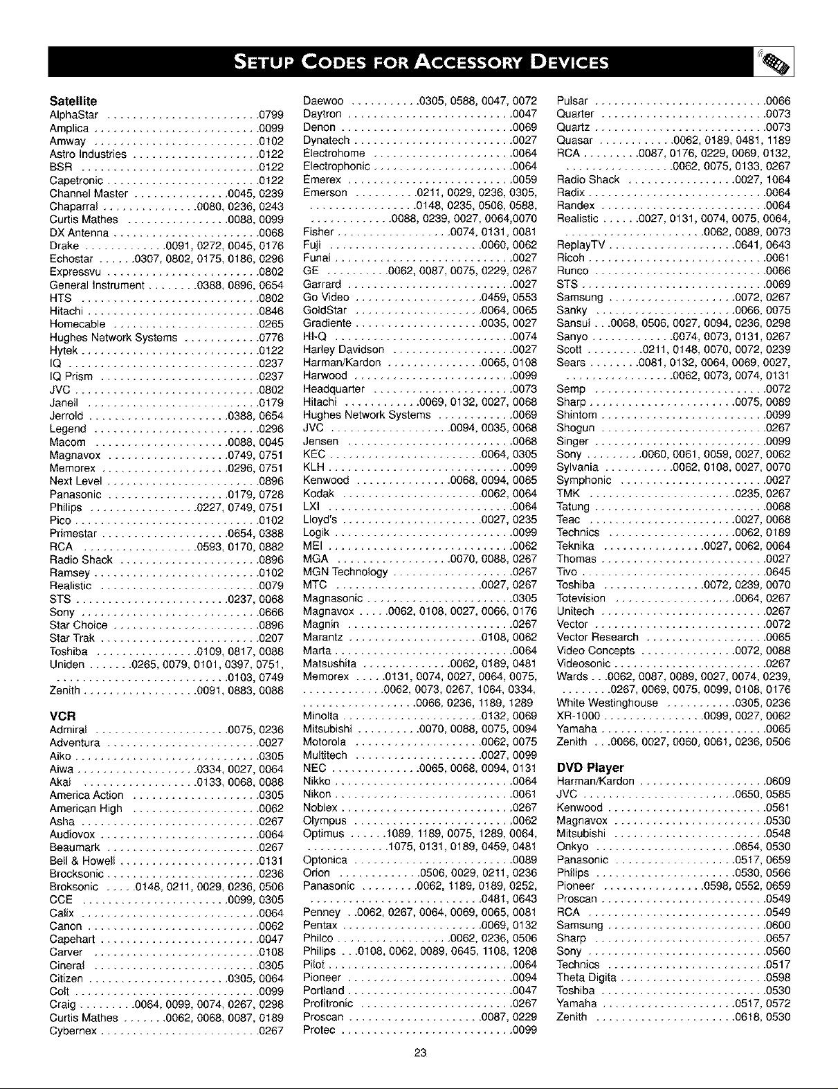
Satellite
AlphaStar ........................ 0799
Amplica .......................... 0099
Amway .......................... 0102
Astro Industries .................... 0122
BSR ............................ 0122
Capetronic ........................ 0122
Channel Master ............... 0045, 0239
Chaparral ............... 0080, 0236, 0243
Curtis Mathes ................ 0088, 0099
DX Antenna ....................... 0068
Drake ............. 0091, 0272, 0045, 0176
Echostar ...... 0307, 0802, 0175, 0186, 0296
Expressvu ........................ 0802
General Instrument ........ 0388, 0896, 0654
HTS ............................ 0802
Hitachi ........................... 0846
Homecable ....................... 0265
Hughes Network Systems ............ 0776
Hytek ............................ 0122
IQ .............................. 0237
IQ Prism ......................... 0237
JVC ............................. 0802
Janeil ........................... 0179
Jerrold ...................... 0388, 0654
Legend .......................... 0296
Macom ..................... 0088, 0045
Magnavox ................... 0749, 0751
Memorex .................... 0296, 0751
Next Level ........................ 0896
Panasonic ................... 0179, 0728
Philips ................. 0227, 0749, 0751
Pico ............................. 0102
Primestar .................... 0654, 0388
RCA .................. 0593, 0170, 0882
Radio Shack ...................... 0896
Ramsey .......................... 0102
Realistic ......................... 0079
STS ........................ 0237, 0068
Sony ............................ 0666
Star Choice ....................... 0896
Star Trak ......................... 0207
Toshiba ................ 0109, 0817, 0088
Uniden ....... 0265, 0079, 0101, 0397, 0751,
........................... 0103, 0749
Zenith .................. 0091, 0883, 0088
VCR
Admiral ..................... 0075, 0236
Adventura ........................ 0027
Aiko ............................. 0305
Aiwa ................... 0334, 0027, 0064
Akai .................. 0133, 0068, 0088
America Action .................... 0305
American High .................... 0062
Asha ............................ 0267
Audiovox ......................... 0064
Beaumark ........................ 0267
Bell & Howell ...................... 0131
Brocksonic ........................ 0236
Broksonic ..... 0148, 0211, 0029, 0236, 0506
CCE ....................... 0099, 0305
Calix ............................ 0064
Canon ........................... 0062
Capehart ......................... 0047
Carver .......................... 0108
Cineral .......................... 0305
Citizen ...................... 0305, 0064
Colt ............................. 0099
Craig ......... 0064, 0099, 0074, 0267, 0298
Curtis Mathes ....... 0062, 0068, 0087, 0189
Cybernex ......................... 0267
Daewoo ........... 0305, 0588, 0047, 0072
Daytron .......................... 0047
Denon ........................... 0069
Dynatech ......................... 0027
Etectrohome ...................... 0064
Electrophonic ...................... 0064
Emerex .......................... 0059
Emerson .......... 0211, 0029, 0236, 0305,
................. 0148, 0235, 0506, 0588,
............. 0088, 0239, 0027, 0064,0070
Fisher .................. 0074, 0131, 0081
Fuji ........................ 0060, 0062
Funai ............................ 0027
GE .......... 0062, 0087, 0075, 0229, 0267
Garrard .......................... 0027
Go Video .................... 0459, 0553
GoldStar .................... 0064, 0065
Gradiente .................... 0035, 0027
HFQ ............................ 0074
Harley Davidson ................... 0027
Harman/Kardon ............... 0065, 0108
Harwood ......................... 0099
Headquarter ...................... 0073
Hitachi ............ 0069, 0132, 0027, 0068
Hughes Network Systems ............ 0069
JVC ................... 0094, 0035, 0068
Jensen .......................... 0068
KEC ........................ 0064, 0305
KLH ............................. 0099
Kenwood ............... 0068, 0094, 0065
Kodak ...................... 0062, 0064
LXI ............................. 0064
Lloyd's ...................... 0027, 0235
Logik ............................ 0099
MEI ............................. 0062
MGA .................. 0070, 0088, 0267
MGN Technology ................... 0267
MTC ....................... 0027, 0267
Magnasonic ....................... 0305
Magnavox ..... 0062, 0108, 0027, 0066, 0176
Magnin .......................... 0267
Marantz ..................... 0108, 0062
Marta ............................ 0064
Matsushita .............. 0062, 0189, 0481
Memorex ..... 0131, 0074, 0027, 0064, 0075,
............. 0062, 0073, 0267, 1064, 0334,
.................. 0066, 0236, 1189, 1289
Minolta ...................... 0132, 0069
Mitsubishi .......... 0070, 0088, 0075, 0094
Motorola .................... 0062, 0075
Multitech .................... 0027, 0099
NEC .............. 0065, 0068, 0094, 0131
Nikko ............................ 0064
Nikon ............................ 0061
Noblex ........................... 0267
Olympus ......................... 0062
Optimus ...... 1089, 1189, 0075, 1289, 0064,
............. 1075, 0131, 0189, 0459, 0481
Optonica ......................... 0089
Orion ............. 0506, 0029, 0211, 0236
Panasonic ......... 0062, 1189, 0189, 0252,
........................... 0481, 0643
Penney , ,0062, 0267, 0064, 0069, 0065, 0081
Pentax ...................... 0069, 0132
Philco .................. 0062, 0236, 0506
Philips ...0108, 0062, 0089, 0645, 1108, 1208
Pilot ............................. 0064
Pioneer .......................... 0094
Portland .......................... 0047
Profitronic ........................ 0267
Proscan ..................... 0087, 0229
Protec ........................... 0099
23
Pulsar ........................... 0066
Quarter .......................... 0073
Quartz ........................... 0073
Quasar ............ 0062, 0189, 0481, 1189
RCA ......... 0087, 0176, 0229, 0069, 0132,
................. 0062, 0075, 0133, 0267
Radio Shack ................. 0027, 1064
Radix ............................ 0064
Randex .......................... 0064
Realistic ...... 0027, 0131, 0074, 0075, 0064,
...................... 0062, 0089, 0073
ReplayTV .................... 0641, 0643
Ricoh ............................ 0061
Runco ........................... 0066
STS ............................. 0069
Samsung .................... 0072, 0267
Sanky ...................... 0066, 0075
Sansui...0068, 0506, 0027, 0094, 0236, 0298
Sanyo ............. 0074, 0073, 0131, 0267
Scott ......... 0211, 0148, 0070, 0072, 0239
Sears ........ 0081, 0132, 0064, 0069, 0027,
................. 0062, 0073, 0074, 0131
Semp ........................... 0072
Sharp ....................... 0075, 0089
Shintom .......................... 0099
Shogun .......................... 0267
Singer ........................... 0099
Sony ......... 0060, 0061, 0059, 0027, 0062
Sylvania ........... 0062, 0108, 0027, 0070
Symphonic ....................... 0027
TMK ....................... 0235, 0267
Tatung ........................... 0068
Teac ....................... 0027, 0068
Technics .................... 0062, 0189
Teknika ................ 0027, 0062, 0064
Thomas .......................... 0027
Tivo ............................. 0645
Toshiba ................ 0072, 0239, 0070
Totevision ................... 0064, 0267
Unitech .......................... 0267
Vector ........................... 0072
Vector Research ................... 0065
Video Concepts ............... 0072, 0088
Videosonic ........................ 0267
Wards...0062, 0087, 0089, 0027, 0074, 0239,
........ 0267, 0069, 0075, 0099, 0108, 0176
White Westinghouse ........... 0305, 0236
XR-1000 ................ 0099, 0027, 0062
Yamaha .......................... 0065
Zenith ,, .0066, 0027, 0060, 0061, 0236, 0506
DVD Player
Harman/Kardon .................... 0609
JVC ........................ 0650, 0585
Kenwood ......................... 0561
Magnavox ........................ 0530
Mitsubishi ........................ 0548
Onkyo ...................... 0654, 0530
Panasonic ................... 0517, 0659
Philips ...................... 0530, 0566
Pioneer ................ 0598, 0552, 0659
Proscan .......................... 0549
RCA ............................ 0549
Samsung ......................... 0600
Sharp ........................... 0657
Sony ............................ 0560
Technics ......................... 0517
Theta Digita ....................... 0598
Toshiba .......................... 0530
Yamaha ..................... 0517, 0572
Zenith ...................... 0618, 0530
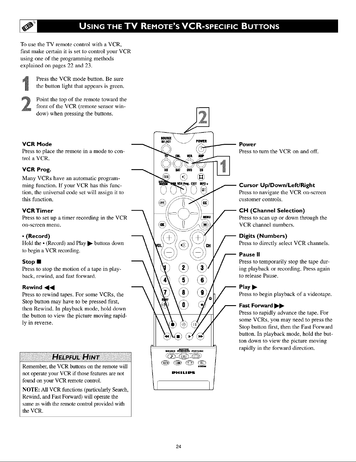
To use the TV remote control with a VCR,
first make certain it is set to control your VCR
using one of lhe programming methods
explained on pages 22 and 23.
Press lhe VCR mode button. Be sure
the button light thai appears is green.
Point the top of the remote toward thefront of the VCR (remote sensor win-
dow) when pressing the buttons.
VCR Mode
Press to place the remote in a mode to con-
trol a VCR.
VCR Prog.
Many VCRs have an automatic program-
ming function. If your VCR has this func-
tion, the universal code set will assign it to
this function.
VCRTimer
Press to set up a timer recording in the VCR
on-screen menu.
• (Record)
Hold the • (Record) and Play _ buttons down
to begin a VCR recording.
Stop •
Press to stop the motion of a tape in play-
back, rewind, and fast forward.
Rewind _1_1
Press to rewind tapes. For some VCRs, the
Stop button may have to be pressed first,
then Rewind. In playback mode, hold down
the button to view the picture moving rapid-
ly in reverse.
Power
Press in turn the VCR on and off.
Cursor Up/Down/Left/Right
Press to navigale the VCR on-screen
customer controls.
CH (Channel Selection)
Press to scan up or down through the
VCR channel numbers,
Digits (Numbers)
Press in directly select VCR channels,
Pause II
Press in temporarily stop the tape dur-
ing playback or recording. Press again
to release Pause.
Play I_
Press in begin playback of a videotape.
Fast Forward
Press to rapidly advance the tape. For
some VCRs, you may need to press the
Stop button first, then the Fast Forward
button. In playback mode, hold the but-
ton clown to view lhe picture moving
rapidly in the forward direction.
Remember, the VCR buttons on the remote will
not operate your VCR if those features are not
found on your VCR remote control.
NOTE: All VCR functions (particularly Search,
Rewind, and Fast Forward) will operate the
same as with the remote control provided with
the VCR.
24
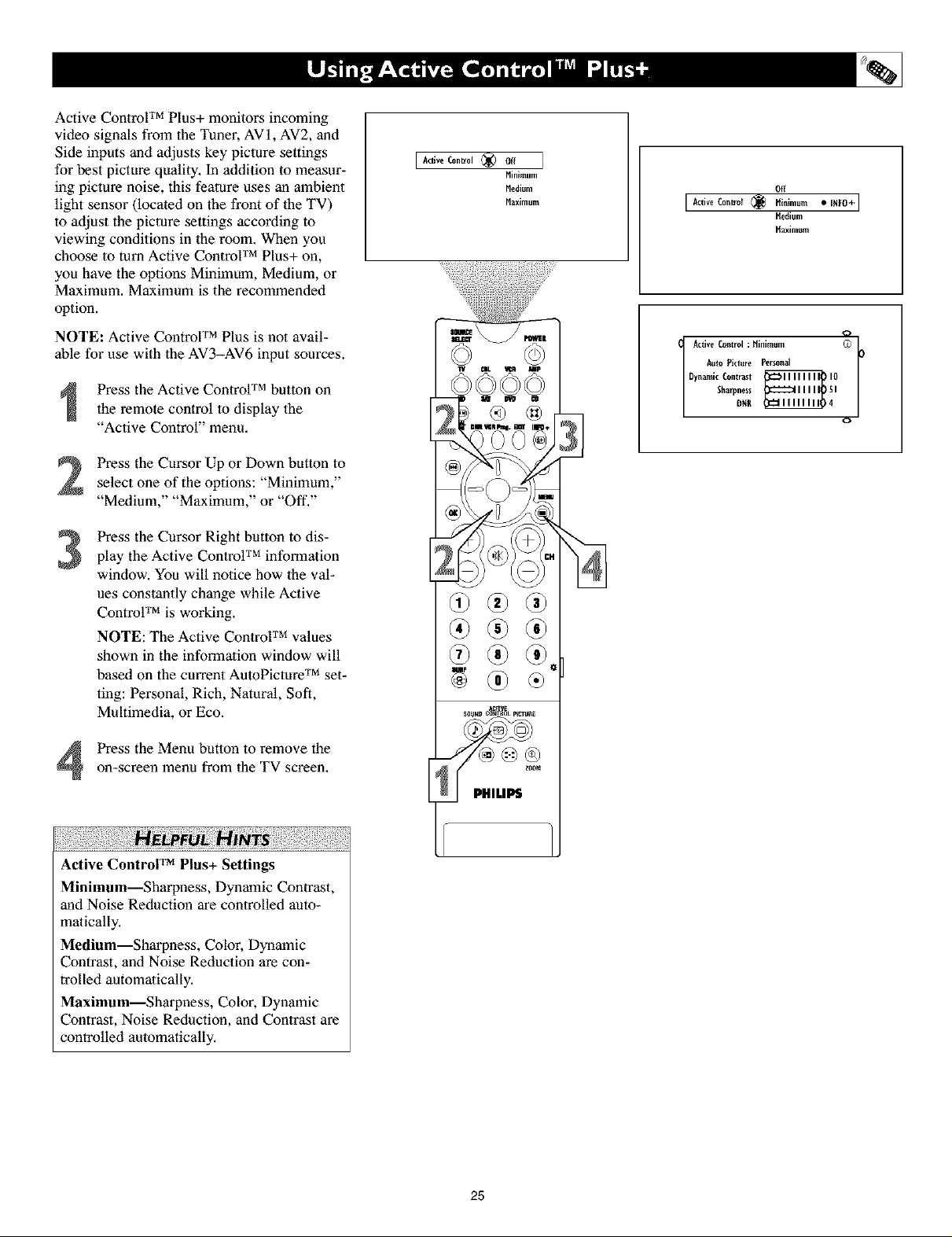
Active Control TM Plus+ monitors incoming
video signals from the Tuner, AVI, AV2, and
Side inputs and adjusts key picture settings
for best picture quality. In addition to measur-
ing picture noise, this feature uses an ambient
light sensor (located on the front of 1heTV)
to adjust the picture settings according to
viewing conditions in the room. When you
choose to turn Active Control TM Plus+ on,
you have the options Minimum, Medium, or
Maximum. Maximum is the recommended
option.
NOTE: Active Control TM Plus is not avail-
able for use with the AV3-AV6 input sources.
Press the Active Control TM button on
the remote control to display the
"Active Control" menu,
Press the Cursor Up or Down button to
select one of the options: "Minimum,"
"Medium," "Maximum," or "Off,"
Press the Cursor Right button to dis-
3
play the Active Control TM information
window. You will notice how the val-
ues constantly change while Active
ControF M is working.
NOTE: The Active Control TM values
shown in the information window will
based on the current AutoPicmre TM set-
ting: Personal, Rich, Natural, Soft,
Multimedia, or Eco.
I Active Control (_) off
[
E
Minimum
Medium
Maximum
Off
[ Active Control (_ [_inimum • _Nt0+]
Active Control : Hinimum (O L*
A_to Picture Personal
Sharpness I
DynamicContlast _ !0
[_edium
[_aximum
o
Press the Menu button to remove theon-screen menu from the TV screen.
Active Control TM Plus+ Settings
Minimum--Sharpness, Dynamic Contrast,
and Noise Reduction are controlled auto-
malically,
Medium--Sharpness, Color, Dynamic
Contrast, and Noise Reduction are con-
trolled automatically,
Maximum--Sharpness, Color, Dynamic
Contrast, Noise Reduction, and Contrast are
controlled automatically,
E
25
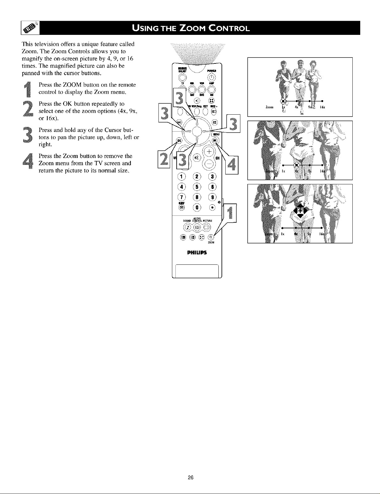
This television offers a unique feature called
Zoom. The Zoom Controls allows you to
magnify the on-screen picture by 4, 9, or 16
times. The magnified picture can also be
panned with the cursor buttons.
Press the ZOOM button on the remote
control to display the Zoom menu.
Press the OK button repeatedly to
select one of the zoom options (4x, 9x,
or 16x).
Press and hold any of the Cursor but-tons to pan the picture up, down, left or
right.
Zoom menu from the TV screen and
Press the Zoom button to remove the
return the picture to its normal size.
ACm_
_Nl_l[t Cl]_H{IL pI_T_IE
PHILIPS
Zoom
Z00_
26
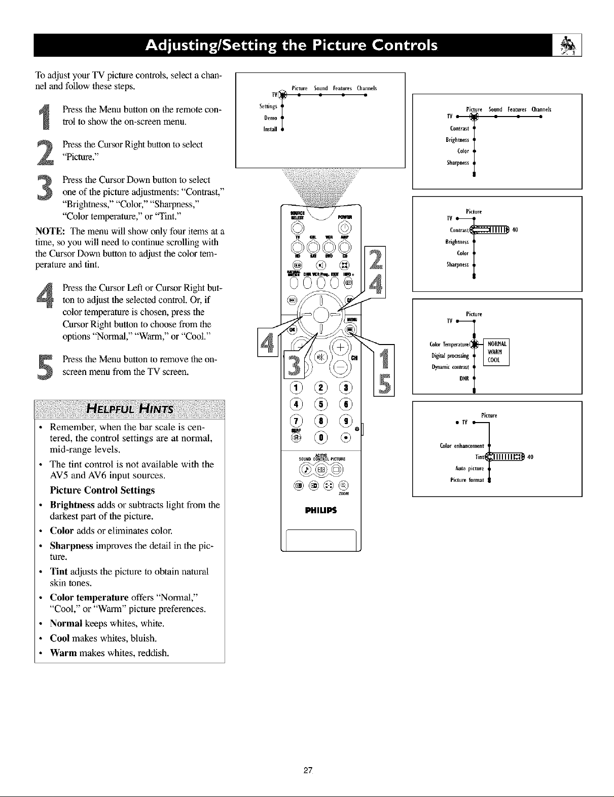
To adjust your TV picture controls, select a chan-
nel and follow these steps.
Picture Sound Features Channels
Press the Menu button on the remote con-
trol to show the on-screen menu.
Press lhe Cursor Right button to select
"Picture."
Press the Cursor Down button to select
one of the picture adjustments: "Contrast,"
"Brigbmess," "Color," "Sharpness,"
"Color temperature," or '_fint."
NOTE: The menu will show only four items at a
time, so you will need to continue scrolling with
the Cursor Down button to at[just the color tem-
perature and tint.
Press the Cursor Left o1"Cursor Right but-
4
ton to adjust the selected control. Or, if
color temperature is chosen, press the
Cursor Right button to choose from the
options "Normal," "Warm," or "Cool."
Press the Menu button to remove the on-
screen menu from the TV screen.
Demo
Settings T
Install
Picture Sound Features Channelx
Brighmes_
Color
C°n_lalt I
Sharpness
Picture
Contr_xt 40
Brighmesx
Color
Sha
Picture
TV
Oigimlprocesslng
Colorler_ramm(
Dym_nlkcon_t I
DR[Ii
• Remember, when the bar scale is cen-
tered, the control settings are at normal,
mid-range levels.
• The tint control is not available with the
AV5 and AV6 input sources.
Picture Control Settings
• Brightness adds or subtracts light from lhe
darkest part of the picture.
• Color adds or eliminates color.
• Sharpness improves lhe detail in the pic-
ture.
• Tint adjusts lhe picture to obtain natoral
skin tones.
• Color temperature offers "Normal,"
"Cool," or "Warm" picture preferences.
• Normal keeps whites, white.
• Cool makes whites, bluish.
• Warm makes whites, reddish.
Picture
Colorenh_ncement
lint 40
Auto pictur_
Pict_ I
zoom
PHILIPS
27
 Loading...