

Page 1
M
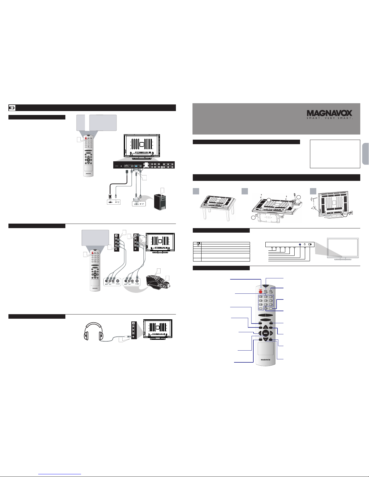
uch like the AV jacks, the SIDE/AV jacks allow for extra accessory
device connections for items such as cameras or gaming stations.
The SIDE/AV Input Jacks are located on the rear of the TV. NP
1
Connect the VIDEO (yellow) adapter cable to the VIDEO AV2 in jack
on the side of the TV. Connect the other end of the VIDEO (yellow)
cable to an RCA type VIDEO Cable. Connect that cable to the VIDEO
OUT jack on the back of the accessory device being used. Note: An
S-Video cable can be used in place of the S-Video cable if your
device is equiped with an S-Video Output. S-Video provides better
video playback.
2
Connect the AUDIO (red and white) adapter cableto an RCA type Audio
Cable. Connect the other ends of the AUDIO (red and white) cables to
the AUDIO (left and right) OUT jacks on the rear of the accessory device
being used.
3
Turn the accessory device and the TV ON.
4
Press the SOURCE button on the remote control to show the Source menu
on the CVBS side or S-Video side under AV2 mode.
5
With the accessory device ON, press the PLY button to activate the playback
on the television.
PC with VGA
OUTPUT
R
L
EARPHONE
SVIDEO-
VIDEO
-
( )
RS232C
FORUPDATE
/ANT
ATSCNTSC
DVIINPUT
LR/
PCINPUT
VGA
LR/
AV
3COMPONENT INPUT
Y
PbCb/
PrCr/
R
L
AV
4COMPONENT INPUT
Y
PbCb/
PrCr/
R L
SVIDEO-
AV1
INPUT
VIDEO
R
L
AV1
INPUT
VIDEO
R
L
AV
INPUT
VGA
BASIC TV OPERATION
First, assemble the TV using the steps below:
TELEVISION
This television has a set of controls located on the side of the cabinet for use when the
remote control is not needed.
REMOTE CONTROL BUTTONS
PC (MONITOR ) INPUTS
HOOKING UP THE TELEVISION
SIDE/AV INPUTS
HEADPHONE CONNECTIONS
VGA
CABLE
HEADPHONE CABLE
1 2 3
C
Jack Panel Bottom of TV
AV2
CVBS SIDE
OR
AV2
S-VIDEO SIDE
2
DVI CABLE
PC with DVI
OUTPUT
PC-
D
OR
To PC
AUDIO IN
English
Quick Setup Guide
B
4
R
L
EARPHONE
SVIDEO-
VIDEO
OR
R
L
EARPHONE
SVIDEO-
VIDEO
2
⑦
⑥
⑤
④
③
②
①
- CH + - VOL +
MENU MODE
①
IR: Remote Control Sensor
②
Power switch: Press to power on or power off the TV set.
③
●
LED: Power Indicator.
④ MODE
Mode: Press to select input signal modes or use as Enter in Menu operation.
⑤ MENU
Menu: Press to enter Menu or exit Menu.
⑥ - VOL +
Left: Press to decrease the sound volume level or move Left in Menu operation.
Right: Press to increase the sound volume level or move Right in Menu operation.
⑦ - CH +
Down: Press to select the next lowe r Pro gramm e numb er or m ove D own in Menu o pera tion.
Up: Press to select the next higher Programme number or move up in Menu operation.
CONTENTS
Important Notice/Warning ........................................ 1
Stand Assembly ...........................................................
1
Basic TV Operation ......................................................
1
Remote Control Button Descriptions ..................... 1
Hooking up the Television
Remote Control Battery Installation......................... 2
Basic Cable/Cable Box TV Connections.................. 2
Basic Antenna TV Connections................................. 2
AV Input Connections ................................................ 3
Component Video Input Connections ................. 3
High Definition Input Connections ........................ 3
PC (Monitor) Input Connections............................. 4
Rear/SVHS Input Connections................................. 4
Headphone Connections........................................... 4
IMPORTANT
NOTE:This owner’s manual is used with several different
television models. Not all features(and drawings) discussed
in this manual will necessarily match those found with your
television set. This is normal and does not require that you
contact your dealer or request service.
WARNING: TO PREVENT FIRE OR SHOCK HAZARD DO
NOT EXPOSE THIS UNIT TO RAIN OR EXCESSIVE
MOISTURE.
A
T
his TV can be used as a PC Monitor. Your computer will
have to be equipped with a VGA (or DVI type video output)
and VGA cable (or a DVI cable).
.
1
Connect one end of the VGA Video cable to the Monitor
(video) output on the computer to the VGA jack
on the bottom of the TV.
OR
if your computer comes with DVI video output, you can
use a DVI cable to connect from the computer's
DVI output to the PC-D input on the bottom of the TV.
2
The TV can reproduce the computer's audio. Using a 3.5mm
Stereo Plug cable, connect the Stereo plug
to the Audio output jack on the computer (if available) while
connecting the PC AUDIO IN on the bottom of the TV.
.
3
Turn the TV and the computer ON.
4
Press the source button on the remote control to show the
SOURCE menu on VGA or DVI mode.
The eadphone jack can be used to connect to a headphone. If connected
to a headphone, there will be no sound from the TV speakers. The sound
will come fom the audio system of the headphone.
1
Connect Headphone jack located on the right rear of the TV to your
headphone set.
2
Turn the TV and headphone ON. TV sound can be heard through the
headphone.
2
3
5
4
1
1
1
3
1
4
“POWER”
To switch TV set between
power on and standby modes.
“MUTE”
To mute the audio output.
“MENU”
To enter
Menu mode.
“ENTER”
To enter sub Menu or sub
item.
“MTS”
To
select audio program
options.
“CC”
To
select close caption options
(CC1, CC2 ...)
“VOL- ( )/ VOL+( )”
To
decrease or increase the
sound volume. Also to navigate
left or right the Menu.
“0~9 number”
To enter TV channel number.
“LAST”
To switch to the previously
viewed channel.
“EPG”
To
enter or exit Electronic
Program Guide.
“SOURCE”
To select input source.
“SLEEP”
To
Adjust sleep timer options.
“•(dot)”
To enter sub channel number.
“CH+ ( )/ CH – ( )”
To select the next higher or
lower channel
.
Also to navigate
up or down the Menu.
“Exit”
To
exit Menu or other OSD.
Page 2
-
( )
RS232C
FORUPDATE
/ANT
ATSCNTSC
DVIINPUT
LR/
PCINPUT
VGA
LR/
AV
3COMPONENT INPUT
Y
PbCb/
PrCr/
R
L
AV
4COMPONENT INPUT
Y
PbCb/
PrCr/
R L
SVIDEO-
AV1
INPUT
VIDEO
R
L
AV1
INPUT
VIDEO
R
L
AV
INPUT
Jack Panel Back of Cable
Boxwith A/V Outputs
C
1
2
3
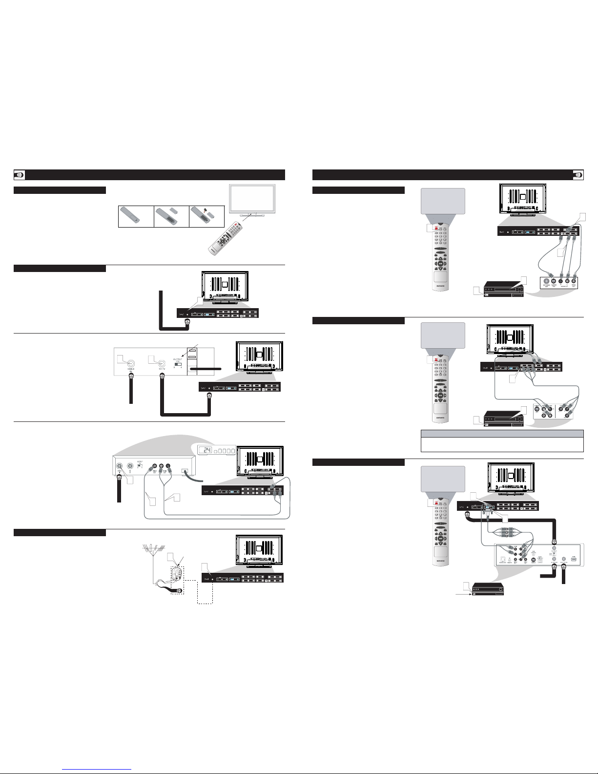
Cable Box (w/Audio/Video Outputs):
This connection will supply Stereo sound to the TV.
Connect the open end of the round Cable Company
supplied cable to the cable signal IN(put) plug on the back
of the Cable Box.
Using an RCA type Video Cable, connect one end of the
cable to the Video (yellow) (or ANT, your cable box may
belabeled differently) Out jack on the cable box and the
other end to the Video In jack on the bottom of the TV.
Using an RCA type Audio Left and Right Cable , connect
one end to the left and right Audio Out L & R jacks (red
& white) on the cable box and the other ends to the Audio
In L & R jacks on the bottom of the TV.
NOTE: Use the AV+ button and the CURSOR DOWN/RIGHT
on the TV remote control to tune to the AV channel for the
cable box signal. Once tuned, change channels at the cable
box, not the television.
Y
our Cable TV input into your home may be a single (75 ohm)
cable or use a cable box decoder: In either case the connection
is very simple. Follow the steps below to connect your cable
signal to your new television.
Direct Cable Connections:
This connection will supplytereo sound to the TV.
1
Connect the open end of the round Cable Company supplied
cable to the 75 input on the bottom of the TV. Screw it down
figer tight.
-
( )
RS232C
FORUPDATE
/ANT
ATSCNTSC
DVIINPUT
LR/
PCINPUT
VGA
LR/
AV
3COMPONENT INPUT
Y
PbCb/
PrCr/
R
L
AV
4COMPONENT INPUT
Y
PbCb/
PrCr/
R L
SVIDEO-
AV1
INPUT
VIDEO
R
L
AV1
INPUT
VIDEO
R
L
AV
INPUT
-
( )
RS232C
FORUPDATE
/ANT
ATSCNTSC
DVIINPUT
LR/
PCINPUT
VGA
LR/
AV
3COMPONENT INPUT
Y
PbCb/
PrCr/
R
L
AV
4COMPONENT INPUT
Y
PbCb/
PrCr/
R L
SVIDEO-
AV1
INPUT
VIDEO
R
L
AV1
INPUT
VIDEO
R
L
AV
INPUT
-
( )
RS232C
FORUPDATE
/ANT
ATSCNTSC
DVIINPUT
LR/
PCINPUT
VGA
LR/
AV
3COMPONENT INPUT
Y
PbCb/
PrCr/
R
L
AV
4COMPONENT INPUT
Y
PbCb/
PrCr/
R L
SVIDEO-
AV1
INPUT
VIDEO
R
L
AV1
INPUT
VIDEO
R
L
AV
INPUT
Jack Panel Bottom of TV
Rear/AV INPUTS
T
HOOKING UP THE TELEVISION
COMPONENT (CVI) INPUTS
32
REMOTE CONTROL BATTERY
2
HOOKING UP THE TELEVISION
CABLE /CABLE BOX TV
Cable Box (w/RF In/Outputs):
This connection will NT supply Stereo sound to the TV . The
sound from the cable box will be mono.
1
ANTENNA TV
HD (HIGH DEFINITION) INPUTS
Be sure to point the remote
control at the remote sensor
window on the front of the
television when using the remote
control to operate the television.
Direct Cable Connection:
Jack Panel Bottom of TV
Cable Box with RF Inputs and Outputs Connection:
Jack Panel Back of Cable Box
Cable Box with Audio/Video Outputs Connection:
Cable Signal IN
from the Cable
Company
Audio Cables L & R
(Red,White)
Antenna Connection:
Outdoor or Indoor Antenna
(Combination VHF/UHF).
The combination antenna
receives normal broadcast
channels 2-13 (VHF) and
14-69 (UHF).
Twin Lead
Wire
Round 75
Coaxial Cable
from Antenna
300 to 75-ohm
Adapter
AUDIO IN
(RED/WHITE)
VIDEO IN (YELLOW)
VCR (or accessory device)(EQUIPPED
WITH VIDEO AND AUDIO OUTPUT JACKS)
COMPONENTVIDEO CABLES
(Green,Blue,Red)
AUDIO CABLES
(RED/WHITE)
ACCESSORY DEVICE EQUIPPED
WITH COMPONENT VIDEO OUTPUTS.
HELPFUL HINT
The description for the component video connectors may differ depending on the DVD player or accessory digital
source equipment used (for example,Y,Pb,Pr;Y,B-Y,R-Y;Y,Cr,Cb).Refer to your DVD player or digital accessory
owner's manual for definitions and connection details.
Analog
Connection
COMPONENT
VIDEO CABLES
(Green, Blue, Red)
Rear of HD Receiver
(Illustration is for
reference only. Your
HD Receiver's jack
panel may be labeled
differently.
Coxial Cable
Lead-in from
Cable Outlet,
Cable Converter
Box, or VHF/
UHF Antenna
Coaxial cable
Lead-in from
Satellite Dish
or Antenna
HD RECEIVER
EQUIPPED WITH
COMPONENT
VIDEO OUTPUTS.
S.
AUDIO
CABLES
Jack Panel Bottom of TV
Cable Signal IN from
the Cable Company
Output Channel Switch
Round 75
Coaxial Cable
1
2
Audio Cables
(Yellow)
1
3
Jack Panel Bottom of TV
1
Jack Panel Bottom of TV
3
5
AV3
COMPONENT1
OR
AV4
COMPONENT2
CVBS REAR
OR
AV1
S-VIDEO REAR
Jack Panel
Bottom of TV
3
5
1
VGA
1
2
3
Cable signal coming from
Cable Company (Round
75 coaxial cable)
1
2
-
( )
RS232C
FORUPDATE
/ANT
ATSCNTSC
DVIINPUT
LR/
PCINPUT
VGA
LR/
AV
3COMPONENT INPUT
Y
PbCb/
PrCr/
R
L
AV
4COMPONENT INPUT
Y
PbCb/
PrCr/
R L
SVIDEO-
AV1
INPUT
VIDEO
R
L
AV1
INPUT
VIDEO
R
L
AV
INPUT
-
( )
RS232C
FORUPDATE
/ANT
ATSCNTSC
DVIINPUT
LR/
PCINPUT
VGA
LR/
AV
3COMPONENT INPUT
Y
PbCb/
PrCr/
R
L
AV
4COMPONENT INPUT
Y
PbCb/
PrCr/
R L
SVIDEO-
AV1
INPUT
VIDEO
R
L
AV1
INPUT
VIDEO
R
L
AV
INPUT
-
( )
RS232C
FORUPDATE
/ANT
ATSCNTSC
DVIINPUT
LR/
PCINPUT
VGA
LR/
AV
3COMPONENT INPUT
Y
PbCb/
PrCr/
R
L
AV
4COMPONENT INPUT
Y
PbCb/
PrCr/
R L
SVIDEO-
AV1
INPUT
VIDEO
R
L
AV1
INPUT
VIDEO
R
L
AV
INPUT
To load the supplied battery into the remote:
1
.
Press and open the cover.
2
Align the batter according to the (+) and (-) as
indicated inside the case.
If television does not respond to the remote control, check the
battery in the remote control:
1
Remove the battery compartment door on the back of the
remote.
Check that the (+) end of the battery (3V) face up correctly.
Reattach the battery compartment door.
Connect the open end of the round Cable Company
supplied cable to the cable signal IN(put) plug on the back
of the Cable Box.
2
Using an RCA type Video Cable, connect one end of the
cable to the Video (yellow) (or ANT, your cable box may
belabeled differently) Out jack on the cable box and the
other end to the Video In jack on the bottom of the TV.
3
Using an RCA type Audio Left and Right Cable , connect
one end to the left and right Audio Out L & R jacks (red
& white) on the cable box and the other ends to the Audio
In L & R jacks on the bottom of the TV.
A
combination antenna receives normal broadcast channels
(VHF 2–13 and UHF 14–69). Your connection is easy because
there is only one 75 (ohm) antenna plug on the back of your
TV's where the antenna goes.
1
If your antenna has a round cable (75 ohm) on the end,
then you're ready to connect it to the TV.
If your antenna has (300 ohm), you first need to attach
the antenna wires to the screws on a 300- to 75-ohm
adapter.
2
Push the round end of the adapter (or antenna) onto the
75(ohm) plug on the bottom of the TV. If the roundend of
the antenna wire is threaded, screw it down finger tight.
4
he audio/video input jacks on the bottom panel of theTV are
for direct picture and sound connections between the TV and
a VCR (or similar device) that has audio/video output jacks.
1
Using an RCA type Video cable, connect one end of the cable
to the Video (yellow) Out jack on the VCR or accessory device
and the other end to the AV Video In jack on the bottom of the TV.
NOTE: A S-Video cable can be used in place of the yellow video
cable if your device is equipped with an S-Video Output. S-Video
provides better video playback.
2
Using an RCA type Audio Left and Right cable, connect one end
to the left and right Audio Out L & R jacks (red & white) on the
VCR or accessory device and the other ends to the Audio In L
& R jacks on the bottom of the TV.
3
Turn the VCR or accessory device and the TV on.
4
Press the SOURCE button on the remote control to show the Source
List menu on the CVBS rear or S-Video rear under AV1 mode.
5
With the VCR (or accessory device)ON and a prerecorded tape
(CD, DVD, etc.) inserted, press the PLAY button to view the tape
on the television.
omponent Video inputs provide the highest possible color and
picture resolution in the playback of digital signal source
material, such as DVD players.
1
Connect the Component (YPbPr1/YPbPr2) Video OUT jacks
from the DVD player (or similar device) to the CVI-1VIDEO Input
(Y green,Pb blue, Pr, red) jacks on the bottom of the TV.
2
Connect the red and white AUDIO CABLES on the rear of the TV
to the Audio (left and right) output jacks on the rear of the
accessory device.
3
Turn the TV and the DVD player (or digital accessory device)
ON.
4
Press the SOURCE button on the remote control to show the Source
List menu on the AV3(YPbPr1) or AV4(YPbPr2).
5
Insert a DVD disc into the DVD player and press the PLAY
button on the DVD Player.
I
f you are using a High Definition receiver that can transmit high
definition programming, the TV can accept those signals through
the HD Inputs located on the bottom of the TV.
1
For Analog Connection, use Component Video cables to connect
the Component ( Y, Pb, Pr) Video Out jacks of the HD Receiver
(or similar device) to the VGA adapter (supplied with the TV ).
Connect the other end of the adapter to the VGA Input jacks on
the bottom of the TV.
2
Connect the red and white audio cable to RCA type Audio
Cables. Connect the audio adapter to the PC Audio In L & R
jacks on the bottom of the TV.
3
Turn the TV and the HD Receiver ON.
4
Press the SOURCE button on the remote control to show the
Source on the VGA mode.
4
3
Replace the cover.
1
4
2
2
 Loading...