

Page 1

R
S
E
R
Owner’s Manual
7
Manuel du Propriétaire
Manual del Propietario
3
LCD TV
1-866-341-3738
3
1-866-341-3738
Necesita ayuda
inmediata?
1-866-341-3738
English
Français Español
MODEL NUMBE
ERIAL NUMB
Page 2

2
t
R
S
b
M4 x 0.629” (16mm)
()
T
g
.
F
the Wall M
k.
F
to y
B
.
The Wall M
.
F
.
I
ll.
y
y.
D
p
t
.
t
.
F
M
.
D
hil
y
l
.
Wh
T
1
s
B
3
s
(
)
www.magnavox.com/support today to get the very most from your purchase.
Return your Product Registration Card or register online at
Registering your model with MAGNAVOX makes you eligible for all of the valuable benefits listed below, so don't miss out. Complete and
return your Product Registration Card at once, or register online at www.magnavox.com/support to ensure:
*Product Safety Notification *Additional Benefits
By registering your product, you'll receive notification
- directly from the manufacturer - in the rare case of
a product recall or safety defect.
Know these
safetysymbols
CAUTION
RISK OF ELECTRIC SHOCK
CAUTION: TO REDUCE THE RISK OF ELECTRIC SHOCK, DO NOT
INSIDE. REFER SERVICING TO QUALIFIED SERVICE PERSONNEL.
WARNING: To reduce the risk of fire or electric shock, this apparatus should not be exposed to rain or moisture and objects filled
with liquids, such as vases,should not be placed on this apparatus.
CAUTION: To prevent electric shock, match wide blade of plug to wide slot, fully insert.
ATTENTION: Pour éviter les choc électriques, introduire la lame la plus large de la fiche dans la borne correspondante de la prise et
pousser jusqu’au fond.
Wall Mount Bracket Ki
ecommended Wall Mount Bracket Kit:
Brand:SANU
Do NOT use screws packed
with Wall Mount Bracket Kit.
Recommended Screw dimension when purchased:
he recommended Wall Mount Bracket Kit (sold separately)
allows the mountin
or detailed information on installing the wall mount, refer to
ount Instruction Boo
unai is not responsible for any damage to the product or injury
ourself or others if you elect to install the TV Wall Mount
racket or mount the TV onto the Bracket on your own
ount Bracket must be installed by experts
DO NOT OPEN
REMOVE COVER (OR BACK). NO USER-SERVICEABLE PARTS
Visit our World Wide Web Site at www.magnavox.com/support
Model #:San25
of the TV on the wall
Registering your product guarantees that you'll
receive all of the privileges to which you're
entitled, including special money-saving offers.
This “bolt of lightning” indicates uninsulated material
within your unit may cause an electrical shock.For the
safety of everyone in your household, please do not
remove product covering.
The “exclamation point” calls attention to features for
which you should read the enclosed literature closely to
prevent operating and maintenance problems.
unai not liable for these types of accidents or
injury noted below
nstall the Wall Mount Bracket on a sturdy vertical wa
If installed onto a ceiling or slanted wall, the TV and Wall
Mount Bracket ma
o not use screws that are longer or shorter than their
ecifi ed length. If screws too long are used this may cause
s
mechanical or electrical damage inside the TV set. If screws
oo short are used this may cause the TV set to fall
Do not fasten the screws by excessive force; this may damage
he product or cause the product to fall, leading to an injury
or safety reasons use 2 people to mount the TV onto a Wall
ounting Bracket
o not mount the TV onto the Wall Mounting Bracket w
our TV is plugged in or turned on. It may result in an electrica
shock injury
en installing the unit on the wall, allow this much space.
op:
Left and right side: 5.9 inche
ottom:
fall which could result in a severe injur
1.8 inches(30cm)
(15cm)
.9 inche
10cm
e
Page 3

h
IMPORTANT SAFETY INSTRUCTIONS
t
pgqp
.
.
.
.
.
.
.
)
th
.
r
d
d
r
.
d
w
.
t
.
s
y,
pply
liquid has
t
lly
d.
ppli
:
;
ppli
;
ppli
lly or
;
ppli
d.
y prop
.
pplying
which
.
g
d
y.
ppli
iling
.
is
.
A
r
f
,
r
t
.
t
.
y
dily injury, prop
,
:
ligned as
.
d
).
g
time.
p
l
.
e
)
)
)
A
E
S
ead before operating equipmen
. Read these instructions
2. Keep these instructions
. Heed all warnings
4. Follow all instructions
. Do not use this apparatus near water.
6. Clean only with a dry cloth
. Do not block any of the ventilation openings
Install in accordance with the manufacturer’s instructions
8. Do not install near any heat sources such as radiators, heat
registers, stoves, or other apparatus (including amplifiers
at produce heat
9. Do not defeat the safety purpose of the polarized o
rounding-type plug. A polarized plug has two blades with
one wider than the other. A grounding type plug has two
ades and third grounding prong. The wide blade or thir
rong are provided for your safety. When the provide
lug does not fit into your outlet, consult an electrician fo
replacement of the obsolete outlet
0. Protect the power cord from being walked on or pinche
articularly at plugs, convenience receptacles, and the point
here they exit from the apparatus
1. Only use attachments/accessories specified by the
manufacturer.
se only with a cart, stand, tripod, bracket, or table
specified by the manufacturer, or sold with the appara-
us. When a cart is used, use caution when moving the
cart/apparatus combination to avoid injury from tip-over.
3. Unplug this apparatus during lightning storms or when un-
used for long periods of time
4. Refer all servicing to qualified service personnel. Servicing i
required when the apparatus has been damaged in any wa
such as power-su
been spilled or objects have fallen into apparatus, the appara-
us has been exposed to rain or moisture, does not operate
norma
5. Damage Requiring Service - The a
A. The power supply cord or the plug has been damaged
B. Objects have fallen, or liquid has been spilled into the
C. The appliance has been exposed to rain
D. The a
E. The a
, or has been droppe
serviced by qualified service personnel when
a
ance
exhibits a marked change in performance
cord or plug is damaged,
ance should be
ance does not appear to operate norma
ance has been dropped, or the enclosure damage
6. Tilt/Stability - All televisions must comply with recommended
nternational global safety standards for tilt
and stabilit
• Do not compromise these design standards by a
xcessive pull force to the front, or top, of the cabinet
• Also, do not endanger yourself, or children, by placin
electronic equipment/toys on the top of the cabinet. Such
tems could unsuspectingly fall from the top of the set an
ause product damage and/or personal injur
7. Wall or Ceiling Mounting - The a
mounted to a wall or ce
manufacturer.
8.
ower Lines- An outdoor antenna should be located
away from power lines
9.
utdoor Antenna Grounding - If an outside antenna
s connected to the receiver, be sure the antenna system
rounded so as to provide some protection against voltage
surges and built up static charges
ection 810 of the National Electric Code, ANSI/NFP
o. 70-1984, provides information with respect to prope
rounding of the mast and supporting structure, ground-
ng of the lead-in wire to an antenna discharge unit, size o
rounding connectors, location of antenna-discharge unit
connection to grounding electrodes, and requirements fo
he grounding electrode. See Figure below
20.
bject and Liquid Entry - Care should be taken so
hat objects do not fall and liquids are not spilled into the
enclosure through openings
Battery Usage CAUTION - To prevent batter
eakage that may result in bo
or damage to the unit
• Install all batteries correctly, with + and - a
arked on the unit
• Do not mix batteries (old and new or carbon an
alkaline, etc.
• Remove batteries when the unit is not used for a lon
erties of its cabinet design
could ultimately overturn the product
only as recommended by the
nglis
ance should be
erty damage
3
Note to the CATV system installer : This reminder is provided to call the CATV system installer’s attention to Article
820-40 of the NEC that
rovides guidelines for proper grounding and, in particular, specifies that the cable ground shal
be connected to the grounding system of the building, as close to the point of cable entry as practical
Example of Antenna Grounding as
per NEC - National Electric Cod
ROUND CLAMP
ELECTRIC SERVICE EQUIPMENT
NTENNA LEAD IN WIR
ANTENNA DISCHARGE UNIT (NEC SECTION 810-20
ROUNDING CONDUCTORS (NEC SECTION 810-21
ROUND CLAMP
OWER SERVICE GROUNDING ELECTRODE SYSTEM (NEC ART 250, PART H
Page 4
CC WARNIN
G
E
g
Y
X
.
l:0Add
.
7
Like all LCD products, this set contains a lamp with Mercury, please dispose of according to all Local, State and
v
G
.
.
m
W
.
.
E
.
A
.
.
G
.
A
.
d
th
.
.
.
t
.
.
This apparatus may generate or use radio frequency energy. Changes or modifications to this apparatus may cause harmful interference
unless the modifications are expressly approved in the manual. The user could lose the authority to operate this apparatus if an
unauthorized change or modification is made.
ADIO-TV INTERFERENC
This apparatus has been tested and found to comply with the limits for a Class B digital device, pursuant to Part 15 of the FCC Rules.
These limits are designed to provide reasonable protection against harmful interference in a residential installation. This apparatus
enerates, uses, and can radiate radio frequency energy and, if not installed and used in accordance with the instructions, may cause
harmful interference to radio communications. However, there is no guarantee that interference will not occur in a particular installation.
If this apparatus does cause harmful interference to radio or television reception, which can be determined by turning the apparatus off
nd on, the user is encouraged to try to correct the interference by one or more of the following measures:
) Reorient or relocate the receiving antenna.
2) Increase the separation between the apparatus and receiver.
3) Connect the apparatus into an outlet on a circuit different from that to which the receiver is connected.
4) Consult the dealer or an experienced radio/TV technician for help.
DECLARATION OF CONFORMIT
rade Name:MAGNAVO
ode
esponsible Party:UNAI CORPORATION, Inc
ress:9900 Van Ness Avenue, Torrance, CA 90501 U.S.A
elephone Number:1-866-341-3738
his Class B digital apparatus complies with Canadian ICES-003. Standard Television Receiving Apparatus, Canada BETS-7 / NTMR-
AUTION :
WARNING :
Danger of explosion if battery is incorrectly replaced. Replace only with the same or equivalent type.
Batteries (battery pack or battery installed) shall not be exposed to excessive heat such as sunshine, fire or the like.
Disconnect the mains plug to shut off when find trouble or not in use. The mains plug shall remain readily operable.
is apparatus should not be placed in a built-in installation such as a bookcase or rack unless proper ventilation is provided.
Make sure to leave a space of 4 inches (10cm) or more around this apparatus.
WARNING:
Do not place the unit on the furniture that is capable of being tilted by a child and an adult leaning, pulling, standing or
climbing on it. A falling unit can cause serious injury or even death.
o prevent injury, this apparatus must be securely attached to the wall in accordance with the instructions.
Federal laws. For the disposal or recycling information, contact:
www.mygreenelectronics.com or www.eiae.org
The American Academy of Pediatrics discourages television
iewing for children younger than two years of age.
NOTE ABOUT RECYCLIN
This unit’s packaging materials are recyclable and
can be reused. Please dispose of any materials in
accordance with your local recycling regulations
Batteries should never be thrown away or incinerated
but disposed of in accordance with your local
regulations concerning chemical wastes
or product recycling information, please visit - www.magnavox.co
HEN CARRYING THIS UNIT
At least 2 people are required when
carrying this unit
ake sure to hold the upper and bottom
frames of the unit fi rmly as illustrated
O AVOID THE HAZARDS OF
ELECTRICAL SHOCK AND FIR
Do not handle the AC power cord with wet hands
Do not pull on the AC power cord when disconnecting it from an
C outlet. Grasp it by the plug
Do not put your fi ngers or objects into the unit
OCATION AND HANDLIN
o not install the unit in direct sunlight or in a place subject to dust
or strong vibration
void a place with drastic temperature changes
Install the unit in a horizontal and stable position. Do not place
anything directly on top or bottom of the unit. Depending on your
external devices, noise or disturbance of the picture and / or sound
may be generated if the unit is placed too close to them. In this
case, please ensure enough space between the external devices an
e unit
Depending on the environment, the temperature of this unit may
ncrease slightly. This is not a malfunction
Be sure to unplug the AC power cord from the AC outlet before
moving or carrying the unit
Trademark Information
HDMI, the HDMI Logo, and High-Defi nition Multimedia Interface are
rademarks or registered trademar ks of HDMI Licensing LLC in the
nited States and other countries
ouble-D symbol are trademarks of Dolby Laboratories
Page 5

h
Child Safety
nglis
Page 6

INTRODUCTION
s
Y
.
Y
DTV
.
A
Thi
lly
y
.
k
T
.
.
r
A
.
y
ill
.
Y
.
:
.
n
l.
d
.
f
k
)
the HDMI
TV.
t
DVI I
t
W
.
t
t
t
Th
.
t
t
3
T
4
7
7
A
7
7
9
T
9
A
p
1
2
2
2
T
3
3
T
4
4
4
7
3
4
7
T
1
1
1
3
.
A
thi
hibited.
.
with the
g
.
Contents
Important Safety Instructions
rademark Information
hild Safety 5
INTRODUCTION
eatures 6
upplied Accessories
mbols Used in this Manual
ttaching the Base
ounting the Unit on Your Furniture
Remote Control Function 8
Installing the Batteries 8
ontrol Panel
erminals
PREPARATION
ntenna Connection 10
onnection to Cable Receiver or Satellite Box 10
lug In the AC Power Cord 10
1
Initial Setu
WATCHING TV
leep Timer 1
witching Each Input Mode 1
reeze Mode 1
hannel Selection 1
V Screen Display Mode 1
ound Functions 1
V Screen Information 1
ECO 1
fun-Link Options 1
USING FUNCTIONS
icture 16
ound 16
etup 1
eatures 18
Language 2
SB 2
CONNECTING DEVICES
External Device Connection 25
able Management 2
USEFUL TIPS
AQ 28
roubleshooting Guide 28
INFORMATION
lossary 30
Maintenance 30
eneral Specifi cations 3
Electrical Specifi cation 3
ther Specifi cations 3
Limited Warranty 3
eature
DTV / TV / CATV
ou can use your remote control to select channels which are
roadcast in digital format and conventional analog format. Also,
able subscribers can access their cable TV channels
Information Display (ATSC only)
ou can display the title, contents and other information of the
urrent
utoprogram
our area, eliminating diffi cult setup procedures
hild Loc
programs
losed Caption Decoder
Built-in closed caption decoder displays text for closed caption
supported programs
MTS / SAP Tune
Auto Standb
If there is no input signal and no operation for 15 minutes, the
nit w
Sleep Timer
ou can set the unit to go into standby mode after a specifi c
amount of time
hoices for On-screen Language
elect your on-screen language
English, Spanish or French
Stereo Sound Functio
LL Frequency Synthesized Tuning
Various Adjustment for Picture and Soun
sound preference
un-Link via HDMI Lin
HDMI Cable not Included
fun-Link allows your other HDMI link devices to be controlled by
monitor if your PC has a DVI output terminal
omponent Video Inpu
S-Video Inpu
AV Inpu
USB Terminal
Digital Audio Outpu
Analog Audio Outpu
program on the TV screen
s unit automatica
his feature allows you to block children’s access to inappropriate
udio can be selected from the remote control
go into standby mode automatically
rovides free and easy channel selection and lets you tune
irectly to any channel using the number and decimal point “
uttons on the remote contro
ustomizes image quality suitable for your room and sets your
cable connected to your
Inpu
-
npu
hen using HDMI 1 Input, you can enjoy this unit as a PC
e picture (JPEG) and video (Motion JPEG) fi les stored on a
SB storage device can be played back on this unit
scans and memorizes channels available in
2011 Funai Electric Co., Ltd
ll rights reserved. No par t of this manual may be reproduced, copied, trans mitted, disseminated, transcribed , downloaded or stored in any storage
medium, in any form or for any purpose without the express prior written consent of Funai. Furthermore, any unauthorized commercial distribution of
s manual or any revision hereto is strictly pro
Information in this docu ment is subjec t to change witho ut notice. Funai reser ves the right to change the content herei n without the obligation to notify
any person or organization of such changes
of Funai. All other trade mark s used herein r emain the exclusive property of their respective owner s. Nothing contained in this manual should be
constr ued as granting, by implicat ion or otherw ise, any license or r ight to use any of the trademark s displayed herein. Misuse of any trademarks or
any other content in this manual is st rictly prohibited. Funai shall ag gressively enforce i ts intellectual proper ty rights to the fullest ex tent of the law.
MAGNAVOX is a re
Inc. under license from Philips Electronics Nor th America
design is a regis tered trademark of Funai Ele ctr ic Co., Ltd. and may not be used in any way wit hout the express written consent
istered trade mark of Philips Elec tronics Nor th Amer ica Corporat ion and is used by Funai El ectric Co . Ltd. and Funai C orporation,
Page 7

h
Supplied Accessorie
s
t
d
s
AAA
AAA
.
.
.
W
.
T
p
:
ATS C
NTSC
h.
A
Y
.
At least 2 people are required for these steps.
N
T
t st
I
t
s
),
th
the di
until it
Dri
Philli
i
th
ight.
Philli
A
r
of
t
.
W
.
.
.
W
w
.
.
Wh
d
.
wner’s Manual
emote
ontrol
NF805UD)
atterie
AAA, 1.5V x 2)
Note
If you lose the screws, please purchase (M4 x 20)
screws at your local store
If you need to replace these accessories, please refer to the part
name or No. with the illustrations and call our toll free customer
support line found on the cover of this manual
When using a universal remote control to operate this unit.
ake sure the component code on your universal remote control
s set to our brand. Refer to the manual accompanying your
remote control for more details
e do not guarantee 100% interoperability with all universal
remote controls
uick Start Guide
If you have any questions, please visit our website at
www.
magnavox.com/suppor
Quick
Start
EN
Installation
FR
Installation
ES
Instalación
Best
Better
Good
screws
egistration car
M4 x 20)
ps head
Symbols Used in this Manual
he following is the description for the symbols used in this
manual. Descri
If neither symbol appears, the operation is applicable to
tion refers to
: Digital TV operation
: Analog / Cable TV operation
ot
nglis
INTRODUCTION
ttaching the Base
ou must attach the base to the unit to have it as a table top
nit. Be sure the front and rear of the base match the proper
rection
Check the text “FRO
with “arrow“ on the Base’s
ottom to ensure it is being installed in the correct
irection. Spread a thick and soft cloth over a table as shown
a
ep 2. Place the main unit face
own onto it. Make sure
ot to damage the screen.
2
nsert 2 hooks under
he bottom of the main
nit into base
ole
(shown by arrow
en move the base in
rection as shown
y arrow
stops and the screw
oles are aligned.
ve
screws
ps head
nto the
readed holes at the
ottom of the base
ntil they are t
To remove the base from this unit
nscrew the
fter the screws are removed, pull the base up toward the rea
he unit. Be careful not to drop the base when you remove it
ps head screws in step 3
Note
hen attaching the base, ensure that all screws are tightly fastened.
If the base is not properly attached, it could cause the unit to fall,
resulting in injuries as well as damage to the unit
Make sure to use a table which can support the weight of this unit
and is larger than this unit
ake sure the table is in a stable location
hen attaching the base, ensure that “FRONT”with “arrow”
ritten on the bottom of the base is
ownward , the 2 hooks don’t fi t into the base
ownward . If it’s not
ounting the Unit on Your Furniture
crew this unit on your furniture tightly using wood screw (not
upplied) in the hole at the back of the base as shown
Recommended screw dimension : 3/16 x 3/4 inches (5.1 x 20 mm)
PREPARATION WATCHING TV
USING FUNCTIONS
CONNECTING DEVICES
USEFUL TIPS
INFORMATION
Note
en you remove this unit make sure to unscrew the woo
screw from your Wood Stand, Furniture and other wood item
Page 8
8
s
.
AAAAAAAAA
AAA
AAAAAA
.
.
t
.
.
1
.
T
d.
P
➠
E
➠
➠
.
1
1
K
4
l.
.
5
4
D
B
k.
G
t
.
F
k.
k.
4
.
.
Press to call up various menu from your fun-Link device
HDMI
.
.
.
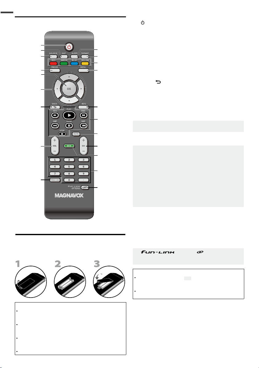
Remote Control Function
1
2
3
4
5
6
7
8
9
nstalling the Batterie
Install the batteries (AAA, 1.5V x 2) matching the polarity
ndicated inside battery compar tment of the remote control
Battery Precautions:
Be sure to follow the correct polarity as indicated in the battery
compartment. Reversed batteries may cause damage to the
evice
Do not mix different types of batteries together (e.g. Alkaline and
arbon-Zinc, or rechargeable batteries like ni-cad, ni-mh, etc) or
old batteries with fresh ones
If the device is not to be used for a long period of time, remove
he batteries to prevent damage or injury from possible batter y
eakage
o not try to recharge batteries; they can overheat and rupture
10
11
12
13
14
15
16
17
18
19
20
1 (power)
ress to turn the unit on and go into standby mode
o completely turn off the unit, you must unplug the AC
power cor
SA
SOURC
ress to freeze screen image
▲/▼/◄/►(cursor)
BAC
8 VOL +/−
REV CH
9
ress to return to previously viewed channe
➠
p. 1
p. 13
p. 12
p. 12
p. 1
p. 1
p. 1
p. 13
p. 12
0 SLEEP p. 12
FORMAT
ress to select aspect ratio available for the TV screen
RED / GREEN / BLUE / YELLOW
3
p. 13
22
p. 1
4 INFO p. 1
5
E / FWD
ress to begin the disc playbac
SKIP H / SKIP
racks of the disc
AUSE
ress to pause the disc playbac
STOP C
ress to stop the disc playbac
6
7
H +/−
8 ECO
ress to reduce power consumption
9
umber buttons
• (dot)
Press to shift the subchannel from the main channel
20 OPTIONS
onnected through an
Note
Buttons in gray background ( ) are not available unless you
are connected to devices that are compatible with fun-Link
function
We do not guarantee 100% interoperability with other brands of
link compliant devices
cable
22
22
22
22
22
p. 13
p. 12
p. 1
p. 12
p. 14, 22
Page 9
h
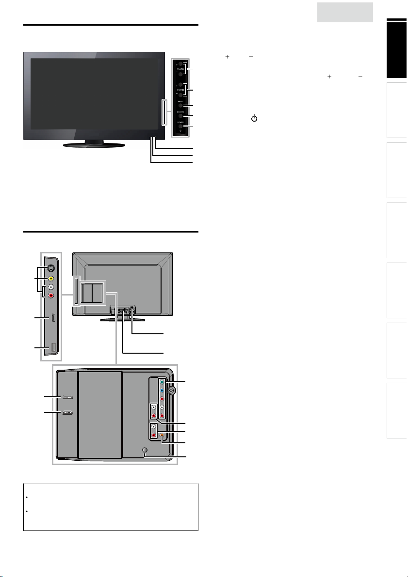
Control Panel
7
6
8
2
4
)
(
)
.
)
th
.
5
R
1
dby
.
T
l
y
d.
w
l.
r
.
dby
.
s
f
7
v
.
l
0
7
s
s
p
7
1
7
A
.
W
,
ll.
y)
7
0
7
.
W
,
y
.
T
t
.
VOLUME + / −
ress to adjust the volume up /down or move right
/ left
through the main menu items
2
1
HANNEL + / −
ress to select channels or move up )/ down
rough the main menu items
3
3
4 SOURCE
5
OWE
ress to turn the unit on and go into stan
o complete
ower cor
turn off the unit, you must unplug the AC
Infrared sensor windo
Receives infrared rays transmitted from the remote
ontro
ower on indicato
ghts up green when power is on
8 Stand by indicator
ts up red when the unit goes to stan
nglis
p. 13
p. 12
p. 1
p. 12
p. 1
mode
mode
9
INTRODUCTION
PREPARATION WATCHING TV
USING FUNCTIONS
Terminals
9
10
12
11
19
20
Note for USB terminal
ser should not connect any devices to the USB terminal such as
igital camera, keyboard, mouse, etc. (because these will not work)
he software update is, in most cases, handled by an authorized
service person or in some circumstances the user may be asked
o do the software update themselves
13
Side Panel
9 S-Video / Composite Video / Audio (L/R) Input jack
or VIDEO
0 HDMI 2 Input jack
SB terminal
se this terminal only to play back the picture (JPEG) and
ideo (Motion JPEG) fi lesstored on a USB storage device,
r when software update is needed
p. 26
p. 10, 25
p. 2
ear Pane
2 AC power cord Inlet
3
able management
p. 1
p. 2
Component Video and Audio (L/R) Input jack
CONNECTING DEVICES
USEFUL TIPS
p. 10, 26
14
5 Analog Audio (L/R) Output jack
. 2
INFORMATION
6 Analog Audio (L/R) Input jacks for HDMI
nput jack
15
16
17
18
udio cable connection from a DVI device
hen you connect your PC that has a DVI terminal
use a stereo mini plug conversion cable as we
For
D
Input jack onl
7 Digital Audio Output jack p. 2
8 Antenna Input jack
9 HDMI 1 (HDMI-DVI) Input jack
HDMI connection for HDMI or DVI device
hen you connect your PC that has a DVI terminal
ou can enjoy this unit as a PC monitor.
20 HDMI 3 Input jack
p. 25, 2
p. 1
p. 10, 25, 2
p. 10, 25
Page 10

REPARATION
.
p
.
VHF / UHF VHF / UHF
ee cab
i
]
1
.
t
.
.
.
.
jack
.
o
able
c
Y
lli
.
.
.
d
.
t
.
.
Each ti
.
No supplied cables are used with these connections:
• Please purchase the necessar y cables at your local store.
Before you connect:
e sure your antenna or other device is connected properly
before plugging in the AC power cord
Antenna Connection
onnect the RF coaxial cable on your home outlet to the
antenna in
ut jack of this unit
or
Connection to Cable Receiver or Satellite Box
se an HDMI or Component Video cables to connect the
HDMI or the Component Video Input jacks of the unit to the
HDMI or the Component Video output jacks of the cable
receiver / satellite box
If you connect to the unit’s Component Video Input jacks,
onnect Analog Audio cables to the Analog Audio L/R Input
s right
elow the Component Video connector jacks
COMPONENT VIDEO OUT
ANT IN
AUDIO OUT
Pr/CrPb/CbY
STEREO
PCM
HDMI OUT
RL
or
or or
or
nce connections are completed, turn on the unit and begin
nitial setup. Channel scanning is necessary for the unit to
memor
ze all available channels in your area.
p. 1
Note
If you have any question about the DTV’s antenna, visit
www.antennaweb.org for fur ther information
Depending on your antenna system, you may need different types
f combiners (mixers) or separator s (splitters) for HD TV signal
he minimum RF bandpass on these devices is 2,000MHz or 2GHz
For your safety and to avoid damage to this unit, please unplug the
RF coaxial cable from the antenna input jack before moving the
unit
If you did use an antenna to receive analog TV, it should also
work for DTV reception. Outdoor or attic antennas will be more
effective than a set top or inside antenna
To switch your reception source easily between antenna and cable,
nstall an antenna selector.
If you are not receiving a signal from your cable service, contact the
able provider.
Initial Setup
ou can also connect this unit to the cable receiver or sate
te
ox other than the HDMI or the Component Video output jacks
r Composite Video output jack (. 2 6) because they might
ave different output jacks
Required cables and connecting methods of the cable receiver /
atellite box, or the availability channel for the clear QAM may
iffer depending on the cable / satellite provider or local TV
roadcaster.
or more information, please contact your cable / satellite provider
r local TV broadcaster.
Note
se an HDMI cable with the HDMI logo (a certifi ed HDMI cable)
High Speed HDMI cable is recommended for the better compatibility
lug In the AC Power Cor
Make sure that the AC power cord must be plugged to an AC
utlet after all the necessary connections are made
Caution:
Do not connect the AC power cord to a power supply outside
he indicated voltage of this unit (AC 120V)
onnecting the AC power cord to a power supply outside of this
range may result in fi re or electrical shocks
Note
me you
performed for a few seconds. This is not a malfunction
lug in the AC power cord, no operations will be
Page 11

h
These operations are accessible by remote control.
p
T
lly
.
.
,
to turn on the unit.
.
it i
.
TV
]
ill begin.
U
ill b
.
y
t
to y
play.
f
the l
ill be displ
.
]
i
]
ill
.
t
ill b
d.
T
7
.
.
7
Y
.
.
]
.
]
Some may also be accessible by controls on the main unit.
nglis
se
/► to select the desired location setting, then press
Initial Setup
INTRODUCTION PREPARATION
Initial Setu
his section will guide you through the unit’s initial setting
which includes selecting a language for your on-screen menu
and autoprogram, which automatica
viewable channels
Before you begin:
ake sure the unit is connected to antenna or cable
After making all the necessary connections
press
It may take a few moments to turn on the unit for the
first time
Initial Setup]menu appears automatically after the
s turned on
un
Use ▲/▼to select the on-screen language from the
hoices (English / Español / Français) on the right side of the
screen, then press
Use ▲/▼to select
for CATV channels, then press
Initial Setup
Make sure the antenna is connected to ''ANT. IN'' jack.
Select your signal source.
Antenna
Cable
utoprogram]w
Initial Setup
Please wait while the system is scanning for channels.
Auto programming may take more than 20 minutes to
complete.
Digital channels
Analog channels
ntenna]for TV channels or
Or
OK
Select
0%
scans and memorizes
ANT.IN
BACK
OK
Back
0 ch
0 ch
Cable
Antenna
Cable
Skip
MENU
Skip
MENU
Skip
Select “Retail” or “Home” for your location.
Retail
elect
etail] store, the unit w
predefined setting for retail displays
elect
for home setting and it can be adjusted
efficienc
hrough a choice of picture and sound quality according
our preference. Use this setting to remove the
E-Sticker if visible from the dis
When the initial setup is completed, the lowest
memorized channel with the confirmation message o
ocation setting w
You must set
and
Sound]settings you adjusted w
memorized after the unit goes into standby mode
Select
ome], the unit is set to maximize the energy
ome
Home
OK
OK
e set up with
p. 23
ayed on the TV screen
n step 4. Otherwise,
not be
Note
If you are not receiving a signal from your cable service, contact
he Cable provider.
If you pressor
annels w
he initial autoprogram function can be executed for either
ntenna]or
onnection (Antenna / Cable), set
If there is no signal input from the antenna terminal and no
eration for several seconds after you turn on the unit, helpful
nts appears. Follow the instructions listed on the TV screen
Initial Setup
No channel is registered.
Try Autoprogram again?
Verify that you have a cable connected to the “ANT. IN” jack
on the back of the TV, the channel installation process
searches this connection. If you are using a cable or satellite
box, please confirm the input which you have connected to the
box and press “SOURCE” key on the remote control to select
the appropriate source input.
After an initial setup is completed...
If you want to scan the channels automatically again
utoprogram]
during autoprogram, this setup of TV
e cancele
Cable] only once. When you change the
Select
utoprogram] again. ➠p. 1
OK
MENU
OK
Skip
p. 1
Retry
Later
ou can add the desired cable and analog channels
nmemorized by autoprogram
Add Channels]
p. 18
If you want to change to another language
anguage
p. 23
If you want to change the location setting
ocation
p. 23
icture
WATCHING TV
USING FUNCTIONS
CONNECTING DEVICES
USEFUL TIPS
INFORMATION
Page 12

WATCHING TV
p
t
.
.
T
d.
il
.
.
/ TV
cha
nnel
nput
)
.
g
.
.
Th
ill
d.
T
s
T
,
T
,
ATS C
1
NTSC
1
l.
ill app
l.
Sleepime
ress SLEEP repeatedly to change the amount of time (increases
he time by 30 minutes up to 120 minutes)
ress SLEEP once to call up the display for checking the remaining time
o cancel sleep timer, press
splaye
Switching Each Input Mode can eas
between TV (ATSC or NTSC) and external devices when they are connected to the unit
ress SOURCE or Hrepeatedly to cycle through the input modes
Source
TV
HDMI1
HDMI2
HDMI3
Component
Video
ressing
H − reverses the direction of the input modes
reeze Mode can freeze the ima
ress
to freeze the image
Freeze
e sound output w
o cancel freeze mode, press any buttons except
LEEP repeatedly until
e.g.)
Sleep Off] is
y switch with the remote control
11.1 HDMI1 HDMI2
PC I
Video Component HDMI3
e shown on the TV screen for 5 minutes
not be pause
Sleep 120min.
hannel Selection
elect channels by using
o select the memorized channels
use
H +/− or the Number buttons.
o select the non-memorized channels
use the Number buttons.
H +/− or the Number button
11.1
To use the Number buttons
When selecting digital channel 11.
Be sure to press • before entering the subchannel number.
When selecting cable or analog channel 1
ress
REV CH to return to the previously viewed channe
[No Signal] will appear on the TV screen after the subchannel
roadcast is over.
udio only program]message w
receive only sound signa
Note
ear on the TV screen, when you
Page 13

nglis
h
.
.
l
.
.
d
.
Z
.
Wid
Thi
.
l
Wid
d
Z
l
.
play
.
d
.
Z
play
.
Wid
display
.
l
Wid
d
Z
l
displ
.
ll
.
d
display
iginal size.
l
dull
s
.
.
.
iginal
.
.
w
.
ATS C
.
.
.
11.1
NTSC
th
l.
11
Wh
TV Screen Display Mode
5 types of display modes can be selected when the broadcasting station is sending 16:9 or 4:3 video signal. And 3 types of display
modes can be selected for PC input signal
ress FORMAT repeatedly to switch the TV aspect ratio
orma
For 16:9 video signal
orma
e
For 4:3 video signal
orma
e
For PC input signal
orma
through
4:3
6:9
HDMI1
ovie expan
oom
ovie expan
oom
Input mode
nscale
isplays a 16:9 picture at its original size
4:3
isplays a 16:9 picture at a 4:3 size; the picture is
shortened horizontally. Sidebars appear on both edges
of the screen
ovie expan
vertically stretched to fi ll the screen. This only crops
out the top of the picture
oom
without changing its horizontal and vertical ratio
e
crops out the left and right sides of the picture
orma
idebars appear on both edges of the screen
16:9 dis
stretched horizontally to fi ll the screen
ovie expan
the picture is stretched more vertically at the top of
the screen. This crops out the top of the picture
oom dis
maximum size that is more vertically stretched to fi ll
the screen. This crops out the top and bottom of the
cture
e
original size and the edges stretched horizontally to fi ll
the screen
orma
idebars appear on both edges of the screen
u
displays a picture that is stretched out of
proportion horizontally to fi ll the screen
nscale
isplays a 16:9 picture that is
isplays a 16:9 picture at its maximum size
splays a horizontally stretched picture.
displays a 4:3 picture at its original size.
s a 4:3 picture at a 16:9 size; the picture is
displays a 4:3 picture at a 16:9 size;
s a 4:3 picture at a 16:9 size; at its
s the picture with its center at the
ays a proportionately stretched picture.
s a picture in its or
13
INTRODUCTION
PREPARATION
s
WATCHING TV
USING FUNCTIONS
CONNECTING DEVICES
USEFUL TIPS
Sound Function
escribe how to change the audio or the audio language as well as the volume
Volume Adjustment
se VOL +/− to adjust the volume
Silence Mode
ress
to turn off the sound temporarily
Mute
will be displayed for a few seconds
ress
again or VOL +/− to recover the or
Volume 30
ill be displayed for a few seconds when adjusting the volume
volume
hi!
hola!
salut!
Switching Audio Mode
ress SAP repeatedly to cycle through the available audio
anguages
Available languages differ depending on the broadcast
Other]s displayed when the audio language cannot be
acquired, or the acquired languages are other than English,
panish or French
English 1/3
ress SAP to display the currently selected audio mode.
While receiving an MTS broadcast, press repeatedly to cycle
rough the available audio channe
SAP / STEREO
en all audio are available
SAP / STEREO SAP / MONO SAP / STEREO
STEREO: Outputs stereo-audio
SAP : Outputs second audio program
MONO: Outputs mono-audio
INFORMATION
Page 14

TV Screen Information
Y
.
id
d.
P
O
11.1
TV: TV-14
1080i
1080i
16:9
16:9HDHD
CC
CC
KABC
KABC
1 23 4
5
6, 7, 8
9
10
id
b
r
6
7
’
]
)
hild lock
g
P
K
to hide the information.
▼
t
.
]
is displ
d.
d.
;
.
T
.
O
Y
ion.
.
f
Y
.
s
p
th
HDMI
ply op
v
.
Y
.
X
F
2
1
1
P
.
T
y
.
T
.
e
T
p
.
U
t
.
y
.
pli
.
ou can display the currently selected channel or other
nformation such as the audio mode on the TV screen
In the digital mode, the detailed broadcasting information
for the current off the air channel such as program title and
program gu
es are displaye
ress INF
ATS C
A Day of Memories
A Day of Memories
A quarter-century ago,which may now qualify as the
good old days of newspapering,run-of-paper sales
accounted for 80 percent of the industry's advertising
revenues.Department stores and supermarket were
English 1/2
Rating
EC
ou can turn on ECO Mode to conserve power.
ressECOonce to turn on ECO Mode and reduce
power consumpt
ressECOagain to turn off ECO Mode
ECO Off ECO On
n
f
Note
ou must set
therwise, the settings you adjusted will not be saved when the
unit goes into standby mode
educes power consumption
ets the backlight brighter.
ome] in[Location].
p. 23
NTSC
4
11
SAP / STEREO
480i
480i
TV-PG DLSV
5
4:3SDSD
4:3
6, 7, 8
CC
CC
9
10
1 program title
2 program gu
e
( The program guide added to broadcasting
nformation is displayed to a maximum of 4 lines.)
3
roadcast station
channel numbe
5 audio language (ATSC) / audio mode (NTSC)
Switching Audio Mode]p. 13
effective scanning lines and scan mode
TV format
8 program
s image aspect ratio
9 CC (not available if closed caption is set to
0 c
ratin
ress INFO or BAC
Note
When the program guide consists of more than 4 lines, use ▲/
o scroll to the next / previous lines
o description provided.
s not provide
While the program guide is displayed, the closed caption function
s interrupte
In external input mode, the following screen is displayed
e.g.) When an external device is connected to Video Input jack
ayed when the program guide
Video
SD
480i
SD
480i
CC
CC
TV-PG DLSV
he information display will automatically disappear in 1 minute
Off
un-Link Option
If you have our brand products such as Blu-ray player or DVD
recorder that are com
em to this unit via an
arious items from this unit’s remote control
Before you begin:
ou must set
ontrol].
therwise,
ven if you connected our brand devices to this unit
To enjoy fun-Link, verifi ed and recommended devices are as
follows;
MAGNAVO
MBP5230
MBP2100
MBP5120
MBP5130
ress
fun-Link Options]menu
Device-menu
Devicecontents
Devicefavorit
se ▲/▼/
he desired functions for your devices
Note
ome of fun-Link functions may not be available depending on
our fun-Link devices or discs
We do not guarantee 100% interoperability with other brands of
link com
atible with fun-Link functions, connect
cable so you can sim
On] in
Device Control]and
fun-Link
p. 22
PTIONS does not work
SYLVANIA
MRD723B
MRD410B
B620SL
B620SL
B621SL
PTIONSto display
fun-Link Options
Device-menu
Device-contents
Device-favorite
his function allows you to control the menu of
our connected fun-Link device
his function allows you to control the top menu
f your DVD or Blu-ray discs
his function allows you to control the pop-u
menu of your Blu-ray discs
on this unit’s remote control to operate
ant devices
erate
Page 15

5
h
USING FUNCTIONS
T
T
.
y
th
to determine the setting.
e
d
p
s
ge
e
A
.
d
A
.
p
.
Adj
.
.
Y
.
.
his section describes the overview of the main menu
splayed when you press
he main menu consists of the function setting items below
ress
e main menu
to displa
ictur
oun
etu
eature
angua
B
nglis
Use ▲/▼ to select a desired menu and an item, then
ress
ictur
djusting the picture mode, or customize the
picture quality as your preference
oun
djusting the sound mode, equalizer and some
other sound functions
etu
canning the channels available in your area and
see what the antenna levels are
1
INTRODUCTION
PREPARATION WATCHING TV
USING FUNCTIONS
CONNECTING DEVICES
eatures
usting the Closed Caption, parental guide and
some other useful functions
USEFUL TIPS
INFORMATION
Langua
You can choose English, Spanish, or French
as your on-screen language
ou can view picture (JPEG) and video (Motion
JPEG) fi les stored on a USB storage device
When the setting is completed, press
to exit
Page 16

6
e
Y
]
in
g
.
d
p
uage
.
]
)
]
g.
igh
s
to i
igh
s
t
to d
r
to d
to i
t
t
d
t
t
t
e
t
s
t
s
.
f
.
T
d
Y
]
in
g
.
U
e
p
uage
.
]
)
Adj
y.
dj
Vi
p
.
.
f
.
T
the TV
.
TV
.
f
g.
ictur
Before you begin:
ou must set
therwise, the settings you adjusted will not be memorized
after the unit
Use ▲/▼to select the item you want to adjust, then press
ome
oes into standby mode
Picture
oun
etu
eat
Smart Picture
Brightness
Contrast
Color
Tint
Sharpness
Color Temperature
Noise Reduction
ocation]p. 23
Personal
30
60
36
0
0
Normal
On
2 Adjust the following items
Smart Picture
se ▲/▼ to select the desired setting, then press
ersonal]
Standard]
Brightness, Contrast, Color, Tint, Sharpness,
Color Temperature
You can only adjust the following options when you set to
ersonal]Smart Picture
se ▲/▼ to select the desired setting, then press
use
/► to adjust the settin
rightnessto decrease br
ontras
olo
in
Sharpness
olor
emperatur
Noise Reduction
Reduces the noise of the picture.
se ▲/▼ to select the desired option, then press
n
f
Note
his function is disabled when PC input is selected. (Setting will be
n gray.)
Sports]
ursor ◄
ecrease contrastto increase contrast
ecrease color
ntensity
o add re
o soften
o add warm color
educes noise in an image
ets noise reduction to off
ovie] andGame
tnes
ncrease br
ncrease color
ntensity
o add green
o sharpen
o add cool color
ursor ►
. Then
tnes
oun
Before you begin:
ou must set
therwise, the settings you adjusted will not be memorized
after the unit
ome
ocation]p. 23
oes into standby mode
se ▲/▼to select the item you want to adjust, then press
ictur
Sound
etu
eatures
Smart Sound
Equalizer
Virtual Surround Sound
Auto Volume Leveling
TV Speakers
Primary MTS
Standard
On
Off
On
Stereo
2 Adjust the following items
Smart Sound
se ▲/▼to select the desired setting, then press
ersonal]
Standard]
Equalizer
ust tonal quality for each frequenc
se
/► to select the specifi c frequency and use ▲/▼ to
a
ust the level, then press
Virtual Surround Sound
rtual surround sound gives you the stereophonic virtual
s
ace through your existing 2-channel stereo system
se ▲/▼to select the desired option, then press
n Emphasized effect
f
Auto Volume Leveling
his function keeps a constant loudness differential between
commercials and the programs
se ▲/▼ to select the desired option, then press
n
f
ovie]
usic] and
atural effect
Reduces volume differences between the
commercials and the programs
emoves the auto volume levelin
ews
Page 17

7
h
TV Speakers
HDMI
’
]
i
T
.
f
T
.
Y
l.
Wed
.
t
.
Thi
de b
o
.
o
.
.
p
.
U
e
d
ge
.
f
y
DTV ch
t
.
U
e
d
ures
ge
]
]
ill begin.
ill be displ
d.
A
kip
lly.
t
ill b
d.
ill b
dby
The PIN
ill b
PIN
0
elect the audio output from the unit’s speakers, or not. If your
amplifi er is HDMI link function compatible and connected by
an
cable to this unit, some sound operations such as
volume up can be changed by using this unit
ake sure
fun-Link Control
s set to
s remote control.
On]
p. 22
se ▲/▼ to select the desired option, then press
n
f
xt. Amp
he sound will be output from the unit’s speakers
he sound will not be output from the unit’s
speakers
ou can control audio output from your
onnected HDMI link devices by using this unit's
remote contro
Note
o not guarantee 100% interoperability with other brands of
link compliant devices
nmute]may be displayed on the TV screen when you recover
he volume from your amplifi er.
Primary MTS
You can set the output mode as a default for the sound mode
(NTSC only)
s setting is not interlocked when you change the output
mo
y pressing SAP. [Sound Functions]p. 13
se ▲/▼ to select the desired option, then press
Stere
on
SAP
utputs stereo-audio
utputs mono-audio
utputs second audio program
etu
Before you begin:
ake sure the unit is connected to antenna or cable
se ▲/▼to select the item you want to adjust, then press
ictur
oun
Setup
eat
angua
B
Autoprogram
Channel List
Add Channels
Antenna
nglis
Autoprogram
If you switch wires (e.g. between antenna and CATV) or if you
move the unit to a different area after the initial setting, or i
ou restore the
o use Autoprogram to perform a new channel search
se ▲/▼to select
2
se ▲/▼to select an appropriate option, then press
ictur
oun
Setup
eat
angua
B
When connected to VHF / UHF antenna, select
When connected to CATV, select
utoprogram]w
Please wait while the system is scanning for channels.
Auto programming may take more than 20 minutes to complete.
75%
Digital channels
Analog channels
When the scanning and memorizing are completed, the
owest memorized channel w
Note
fter settingutoprogram], using
s
s unavailable programs automatica
If you are not receiving a signal from your cable service, contact
he Cable provider.
If you press or
annels w
Even if
Autoprogram] is completed, the channel setting w
ost if the AC power cord is unplugged before the unit goes into
stan
mode by pressing
code w
Child Lock]p. 2
If you want to change your PIN code, follow the instruction of
Change PIN]
annels you deleted, it is recommended
utoprogram], then press
Autoprogram will rescan all channels.
Auto programming may take more than 20
minutes to complete.
Select your signal source.
Antenna
Cable
Or
ANT.IN
Cable
10 ch
MENU
Exit
H+ / −
n the remote control
during autoprogram, the setup of TV
e cancele
e required once you set a
6 ch
aye
code in the
Back
Antenna
Cable
ntenna
e
1
INTRODUCTION
PREPARATION WATCHING TV
USING FUNCTIONS
CONNECTING DEVICES
USEFUL TIPS
INFORMATION
Adjust the following items
Page 18

8
Th
h
Th
ill b
s
U
e
d
ge
Y
ill
T
highlighted.
d
ll.
Th
.
.
T
t
.
U
h
e
d
g
uage
d.
ill be displayed
.
ly.
T
l.
U
U
h.
e
d
ge
.
s
U
e
d
p
ge
.
Channel List
e channels selected here can be skipped when selecting the
c
annels using
ose channels can st
Use ▲/▼to select
2
H + / −
e selected with the Number button
Channel List], then press
se ▲/▼to select the channel you want to remove, then
press
Watch / Skip
DTV 11.1
DTV 11.2
DTV 11.3
BACK
Back
ictur
oun
Setup
eat
angua
The channel display for the removed channel darkens.
ou w
H + / −
o reactivate a removed channel, use ▲/▼ and press
. The registered channels are
Highlight channels for
Ch Up / Down key selection.
B
Ch Select
OK
not be able to select the channel again using
When you remove a main channel, its subchannels are
remove
as we
Note
e channel with the
therwise the channel is NTSC
indicated on the display is ATSC
Add Channels
his function lets you add the off the air along NTSC or analog
able channels that were not added by the autoprogram due
o reception conditions at the initial setting
Use ▲/▼to select
2
se the Number buttons to enter the number of the
c
annel you want to add, then press
Add Channels], then press
Antenna Confi rmation
ATS C
his function lets you check the digital signal strength of each
anne
se ▲/▼to select
se the Number buttons or
hannel for which you want to check the digital signal
trengt
Note
If the channel is set to analog channel or external input, you
cannot confi rm the antenna condition
se ▲/▼to select the item you want to adjust, then press
11
ictur
oun
Setup
eatures
Langua
B
eature
ictur
oun
etu
Features
angua
B
ntenna], then press
H+ / −to select the
Current 50 Max 50
Ch Change
Closed Caption
Child Lock
ECO
fun-Link (HDMI CEC)
Location
E-Sticker
Current Software Info
Back
On
Home
- -
11.1
ictur
oun
Setup
eat
Lan
B
For analog channels, select a
channel to be added using
number keys.
For digital channels, you must
perform Autoprogram function.
Ch Change
Add channels
BACK
Back
Note
If setup completes successfully,
splaye
If external input is used, it is not possible to register the channel
andnavailable]w
usingH+ / −, you can select the memorized channels on
dded to the channel list.] is
on the TV screen
Adjust the following items
Page 19

h
Closed Caption
r
.
.
e
d
p
uage
A. Caption Service
U
f
.
Th
TV
.
.
T
.
,
]
.
:
de
ly.
de
.
de
lli
).
B. Digital Caption Service
dditi
DTV h
i
t
.
f
ice.
6
h
.
the b
.
C. Caption Style
Y
tc.
U
▼
So, y ou m us t be P hi li p. Hi!
I’m p le as ed t o me et you.
t
.
t
d.
r
y
d
r
d.
y
e
r
d.
You can view closed captioning (CC) for TV programs,
movies and news. Closed caption refers to text of dialog o
escriptions displayed on-screen
se ▲/▼ to select
ee the following description for setting each item
ictur
oun
etu
Features
B
A. Caption Service
se ▲/▼ to select
se ▲/▼ to select the desired closed caption, then press
f
C-1 and T-1
C-3 and T-3
C-2, CC-4
-2 and T-4
There are 3 display modes according to programs
Paint-on
mo
op-on mo
oll-up mo
B. Digital Caption Service
ATS C
n a
on to the basic closed caption,
capt
on called digital caption service. Use this menu to change
he settings for digital caption service
losed Caption, then press
Caption Service
Digital Caption Service
Caption Style
On
On
ption Service], then press
elect if you do not want caption service
e primary caption and text services. The
captioning or text is displayed in the same language
as the program’s dialog (up to 4 lines of script on the
screen, where it does not obstruct relevant parts
of the picture)
erve as the preferred data channels
he captioning or text is often a secondary
anguage
arely available and broadcasters use them only in
special conditions, such as when
or
T- 1] andT- 3] are not available
splays input characters on the TV screen
mmediate
nce characters are stored in memory, they are
splayed all at once
splays the characters continuously by scro
max. 4 lines
CC-1] andCC-3
as its own closed
Note
Digital Caption Service] that you can switch differs depending on
roadcast description
C. Caption Style
ATS C
ou can change the caption style such as font, color or size,
e
se ▲/▼to select
2
se ▲/▼to select
se ▲/▼to select
se ▲/▼to select an item, then press
▲/
eview your setting choice made below by looking in
he upper right corner of the displayed setting box (not
all selections show the differences selected)
on
ng
ackgroun
g
Caption Style], then press
User Setting], then press
On], then press
to select the desired setting and press
So, you must be Philip. Hi!
So, you must be Philip. Hi!
I’m pleased to meet you.
I’m pleased to meet you.
Font Style
Font Size
Font Colo
ont
pacit
ackground
olo
ackground
pacit
Edge Colo
ge Type
losed captioning font style, size,
color and opacity can be change
Background color and opacity of the
splayed caption can be switche
Edge color and type of the displayed
caption can be switche
nglis
. Then use
19
INTRODUCTION
PREPARATION WATCHING TV
USING FUNCTIONS
CONNECTING DEVICES
USEFUL TIPS
INFORMATION
se ▲/▼ to select
2
se ▲/▼ to select the desired digital caption service, then
press
f
S-1 to CS-
Digital Caption Service], then press
elect if you do not want digital caption
serv
Select one of these before changing any
ot
er item in
hoose
Closed Caption] menu.
CS-1]under normal circumstances
Page 20

2
0
ion.
T
.
.
.
.
Adj
.
A
This i
.
Th
ill
hil
.
]
)
y)
T
.
th
.
t
t
ible.
e
d
p
ge
y
PIN
.
ge
Wh
PIN
ter
PIN
d.
.
ure
d
p
ge
A
Wh
high
w
viewing.
Wh
high
lly.
To block
k]
T
t
0
ill appear
ill b
.
.
T
y.
A. Channel Lock
ible i
t
.
d
e
d
p
ge
2
3
V
o
40.1
V
B. Setting US Movie ratings
.
U
k]
Note
losed caption will not be displayed when you are using an HDMI
connect
o show the closed caption on your TV screen, broadcast signal
must contain the closed caption data
ot all TV programs and commercials have the closed caption or
all types of the closed caption
aptions and texts may not exactly match the TV voice
hanging channels may delay the closed caption for a few seconds
usting or muting the volume may delay the closed caption for
a few seconds
bbreviations, symbols and other grammatical shortcuts may be
used in order to keep pace with the on-screen action.
a malfunction
e caption or text characters w
main menu or functions display is shown
If a black box appears on the TV screen, this means that the closed
caption is set to the text mode. To clear the box, select
CC-2]
CC-3]
If the unit receives poor quality television signals, the captions may
contain errors, or there might be no captions at all. Some possible
causes of poor quality signals are:
- Automobile ignition noise
- Electric motor noise
- Weak signal reception
- Multiplex signal reception (ghosts or screen fl utter
- Data dropout and Pixelation (for DTV onl
he unit retains the closed caption setting if the power fails
When the unit receives special effects playback signal (e.g. Search,
low and Still) from a VCR’s video output channel (ch3 or ch4),
e unit may not display the correct caption or text
CC-4] or
not be displayed w
Off
s not
e the
CC-1]
ict
oun
etu
Features
Langua
B
Channel Lock
US Movie Ratings Lock
US TV Ratings Lock
Canadian English Rating
Canadian French Rating
Region Ratings Lock
Change PIN
Note
en you select a rating and set it to
ill be blocked automatically. The lower ratings will be available for
en you set the
iew] automatica
any inappropriate programs, set your limits in
atings Lock]
he child lock setting will be retained after a power failure or after
he power is removed for longer than 10 seconds (except the PIN
code reverts to 0000).
If the rating is blocked, w
egion Ratings Lock] w
tal broadcast using the new rating system
or the United States, the unit may download the Region Ratings
Lock Table, if required
he Canadian rating systems on this unit are based on CEA-766-A
and CRTC polic
est rating to
US TV Ratings Lock]and
Child Lock]p.2
e available when the unit receives a
ock], the
iew], all ratings turn to
egion Ratings Loc
.
er ratings
US Movie
Child Lock
hild lock reads the ratings for programs, then denies access
o the programs which exceed the rating level you set. With
his function, you can block certain programs inappropriate
for children and any channels or external input modes can be
nvis
Use ▲/▼ to select
ictur
oun
etu
Features
Langua
B
Closed Caption
Child Lock
ECO
fun-Link (HDMI CEC)
Location
E-Sticker
Current Software Info
se the Number buttons to enter the 4-digit numbers for
our
code
Features
Langua
en you have not set up your
splaye
code is correct,
en
When the
ee the following description for setting each item
Enter PIN.
, then press
On
Home
- -
_
code,
Child Lock] menu is
A. Channel Lock
articular channels or external input modes can be invis
his function
se ▲/▼to select
2
se ▲/▼to select the desired rating, then press
Channel L
, then press
repeatedly to switch between View an
ictur
oun
etu
Features
angua
B
Select
B. Setting US Movie ratings
HDMI
HDMI
omponent
ide
DT
OK
View / Block
BACK
Back
S Movie ratings lock is the rating system created by MPAA
se ▲/▼to select
2
se ▲/▼to select the desired rating, then press
repeatedly to switch between
US Movie Ratings Lock], then press
iew]and
oc
n
Page 21

nglis
h
d
p
ge
X
7
3
y
X
7
d
3
G
d
C. Setting TV ratings
repeatedly to switch between
k]
e
d
p
ge
y
MA
r
4
G
d
G
Y7
A
r
Y
A
A
t
.
k]
ure
d
p
ge
y
TV-Y7
V
Viol
T
A
T
4
T
G
T
G
ill app
.
t
]
lly chang
]
).
D. Change PIN
A
y
PIN
.
.
PIN
.
e
d
p
ge
t
g.
.
.
T
.
INTRODUCTION
ict
ating
oun
etu
Features
Langua
B
Select
-1
-1
R
OK
ategor
View / Block
BACK
Back
ature audience only
NC-1
PG-13
P
o one under 17 admitte
Restricted; under 17 requires accompanying
arent or adult guardian
nsuitable for children under 1
arental guidance suggeste
eneral audience
o rating
C. Setting TV ratings
se ▲/▼ to select
US TV Ratings Lock], then press
se ▲/▼ / ◄/► to select the desired rating, then press
-
V-14
V- P
V-
-
-
ating
ictur
oun
etu
Features
Langua
TV-MA
TV-14
TV-PG
TV-G
TV-Y7
TV-Y
Select
FV V S L D
OK
ategor
ature audience only highe
nsuitable for children under 1
arental guidance suggeste
eneral audience
ppropriate for all children 7 and
olde
ppropriate for all children
iew]and
View / Block
oc
BACK
Back
ower
To set the sub ratings
s for TV-MA, TV-14, TV-PG, or TV-Y7, you can further set the
sub ratings to block specifi c elements of programming. To set
he sub ratings, follow the step below
ict
oun
etu
Features
Langua
Sub Rating
TV-MA
TV-14
TV-PG
B
TV-G
TV-Y7
TV-Y
Select
ategor
FV V S L D
View / Block
BACK
OK
Back
ating
antasy Violence
ence
S
exual Situation
oarse Language
uggestive Dialog
V- M
V- 1
V- P
V-14, TV-P
Note
ocked sub rating w
US TV Ratings Lock]menu
You cannot block a sub rating (D, L, S or V) if the main rating is set
o
iew
hanging the category to
all its sub ratings to the same (ock] or
D. Change PIN
ear beside the main rating category in
ock] or
iew]automatica
iew
lthough the default PIN code (0000) is supplied with the unit,
ou can set your own
se ▲/▼to select
2
ressthe Number buttons to enter the new 4-digit PIN
code
Change PIN], then press
ode
nter
ictur
oun
etu
Features
Langua
B
code again in
Confirm PIN.]entry field
Enter PIN.
Confirm PIN.
PIN Code
_
BACK
Back
Note
Make sure new PIN code and confi rm PIN code must be exactly
he same. If they are different, the space is cleared for reenterin
Your PIN code will be erased and returns to the default PIN code
0000) when a power failure occurs
If you forget the PIN code, unplug the AC power cord then wait
for 10 seconds to plug the AC power cord in again
he unit will restore the PIN code to 0000 as the factory default
PREPARATION WATCHING TV
USING FUNCTIONS
es
CONNECTING DEVICES
USEFUL TIPS
INFORMATION
se ▲/▼ / ◄/► to select the desired rating, then press
repeatedly to switch between
iew] andoc
Page 22

EC
O
U
f
Y
]
[L
dby
.
Y
.
4
f
T
i
HDMI
.
e
d
p
ge
A
.
]
T
t t
t
.
f
.
Y
Y
.
f
Y
th
.
T
y
Thi
y
.
f
T
y
.
Y
l.
AY
B
D
E
G
/
P
H
/
l.
fsabl
l.
T
.
ure
d
p
ge
You can turn on ECO Mode to conserve power.
Use ▲/▼to select
2
se ▲/▼to select the desired mode, then press
n
f
ECO], then press
educes power consumption
ets the backlight brighter.
Note
ou must set
therwise, the settings you adjusted will not be saved when the
unit goes into stan
ou can also press ECO directly to switch the desired setting
p. 1
ome
mode
ocation].
p. 23
un-Link (HDMI CEC)
his function allows you to operate the linked functions
between our brand devices with a fun-Link feature and this
un
t connecting through an
Use ▲/▼to select
cable
fun-Link (HDMI CEC)], then press
Auto TV On
his unit will turn on when the power on signal is sent from
our connected fun-Link device.
se ▲/▼to select the desired setting, then press
n
f
s unit turns on automatically when you turn on
our connected fun-Link device
his unit stays in standby mode even if you turn on
our connected fun-Link device
Device Control
ou can operate some functions such as disc playback or call
p the menu of the connected devices, by using this unit’s
remote contro
se ▲/▼to select the desired setting, then press
L
/ STOP C/
SKI
/
AUSE F/
n
f
▲ / ▼ / ◄ / ► /
/
REEN /
ontrol your connected fun-Link devices by this unit’s
remote contro
es the device contro
/
/ SKIP
/ BACK / the Number buttons/
/ YELLOW can be used to
PTIONS
Device List
his function lets you see the product model number or name
f connected devices
Features
Use ▲/
ictur
etu
angua
B
fun-Link Control
Auto Device Off
Auto TV On
Device Control
Device List
to select the desired setting, then press
On
On
On
On
djust the following items
fun-Link Control
et the fun-Link
he following additional settings will be grayed out when you
se
o
se ▲/▼ to select the desired setting, then press
n
f
Off]
On]or
Off
elects if you have connected an external device
hat is compatible with the fun-Link function
Disables all fun-Link
Auto Device Off
ou can set your device to turn off by interlocking from this
nit’s power.
se ▲/▼ to select the desired setting, then press
n
f
our connected fun-Link device turns off
automatically when the unit goes into standby
mode
our connected fun-Link device stays on even if
e unit goes into standby mode
ict
etu
Features
Langua
B
HDMI1 NB620SL2
HDMI2 MBP5230
HDMI3 NRD723B
OK
Refresh
BACK
Back
Page 23

h
ocation
Y
d
t
.
U
l
T
klight brighter
e
y
.
Wh
]
t
.
.
f
p
o
T
d.
.
e
d
p
ge
▲/▼ to select
[Español]
then
ure
d
p
th
.
ou must set
Sound] settings you adjusted will not be memorized after you
urn off the unit
2
etai
om
ome]in this setting. Otherwise,
se ▲/▼to select
ocation], then press
icture] an
se ▲/▼to select the desired location, then press
he unit will be set up with predefined settings
for retail displays. In this setting, you can set the
ac
The unit is set to maximize the energy efficiency
for home setting and it can be adjusted through a
choice of picture and sound quality according to
our preference
.
press
nglis
La
ua
ict
oun
etu
eatures
Language
B
Select your menu language.
Seleccione el idioma para el menú.
Sélectionnez la langue du menu.
or
English
Español
Français
23
INTRODUCTION
PREPARATION WATCHING TV
E-Sticker
en you select
Electronic Sticker) is displayed
E-Sticker can be turned Off using procedure below
se ▲/▼ to select
se ▲/▼ to select
f
o
ottom E-Sticker is displayed on bottom of the TV screen.
Note
If you select
ocation
o
etail] store, E-Sticker
E-Sticker], then press
Off], then press
You can turn off E-Sticker.
E-Sticker is displayed on top of the TV screen.
ome], E-Sticker will not be displayed.
urrent Software Inf
his function shows what version of the software currently
use
se ▲/▼to select
Current Software Info], then press
2 Confi rm the version of the software currently used
ictur
oun
etu
Features
Langua
B
Release Version:
XXXXXXX_XX_XX_XXXX_XX
Back
Note
If you need the English menus instead of the Spanish or French
menus, press
en press
se ▲/▼ to select
ress
. Use ▲/▼ to select
nglish], then press
to exit the main menu
ioma] or
angue]
USING FUNCTIONS
CONNECTING DEVICES
USEFUL TIPS
INFORMATION
Page 24

B
This unit can play
(JPEG) and video (Motion JPEG)
les.
.
thi
.
▼
T
devi
again.
e
d
p
ge
Y
e
g
T
s
T
s
t
.
Th
lid
.
T
(
)
(
).
.
m
l
l
.
]
.
w
lid
.
ill be displayed.
s
;
]
]
lid
.
ill be displayed.
ill
Z
V
Y
o
V
o
T
s
.
m
l
l
.
]
.
to select
ce, then press
This menu allows you to enjoy
your pictures and videos
via your USB device.
USB]and press
se the USB storage device that contains those fi les
Insert the USB storage device into the USB terminal on
s unit. Te main menu appears automatically
2 Use ▲/
he highlighted text will move to the name of your USB
storage
ictur
oun
etu
eat
angua
USB
Your USB
te
ress
to display file details below
fi
ore Detai
tart sho
ransition
Slide time
otate
oom
ame]
ress
again to remove file details
ress4 or
While the slide show is on, the following 2 settings
w
ress 2
then use ▲/▼to select the transition
mode choosing from
one]
up]
ipe down]
ress
then use ▲/▼to change the display time
hoosing from;
ress
or
While the slide show is off, the following 2 settings
w
very press on
90 degrees.
ress
then use ▲/▼to select the zoom factor
1x, 2x or 4x). Press
Detai
lbum]
ate]
Size] andext
to start the s
issolve]
ipe right] [Wipe left]
ox in]and
Short]
edium] andong
to stop the s
w
turn the picture clockwise by
to set the zoom factor.
e show
e show
ox out
ipe
Use ▲/▼ to select
icture]or
ideo]and then press
icture (JPEG)
se ▲/▼ to select the desired fi le, and then press
our USB Pictur
Picture
Image1.jpg
Image2.jpg
Image3.jpg
Image4.jpg
Image5.jpg
Press “OK” key to play/pause.
o toggle between
he Number 2 button each time
e unit goes to the s
o pause / play the slide show, press
sethe Number buttons ( through ) to see the file
etail
or change the following settings
ee the description on the top of the next column
Image1.jp
humbnail
ist]and
umbnails]pres
e show automatically
Image1.jpg
1200:900
2009:04:02 17:42:06
ideo (Motion JPEG)
se ▲/▼ to select the desired fi le, and then press
our USB Vide
ide
MOVIE1.avi
MOVIE2.avi
MOVIE3.avi
MOVIE4.avi
MOVIE5.avi
4321
o stop playback and return to the file list, pres
BACK
ressH to play back from the beginning
or
te
ress
to display file details below
itle]
ore Detai
irector]
ress
again to remove file details
H
MOVIE1.avi
Title: MOVIE1.avi
Director:
Date: 2009/04/02
Duration: 00:06:37
Detai
ate]and
uration
4321
Page 25

5
h
Note
.
A
.
A
.
pp
.
.
To p
th
liding
.
t
to y
.
A
w
d.
T
).
.
d.
.
T
).
T
.
.
g
.
.
T
v
.
.
:
l
Video
s
o
y
)
)
.
digital
.
with the HDMI output jackwith the HDMI output jack
Thi
DVI
t
ll.
with the DVI output jackwith the DVI output jack
ables
The unit recognizes only a USB storage device
Do not use a USB hub or an extension cable to connect an
external hard disk drive to the unit. (Not supported.)
USB storage device is always inserted to this unit directly
USB storage device is not supplied with this unit
We do not guarantee that all USB storage devices can be
orted by this unit
su
Be sure to keep a backup copy of the original fi les on your device
before you play them back on this unit. We have no responsibilities
for damage or loss of your stored data
rotect your USB storage device fi les from being erased place
e write protect s
When you are ready to remove a USB storage device, at fi rst turn
he unit off so it will go into standby mode to avoid any damage
our data and the unit
USB storage device that requires its own driver or the device
ith a special system such as fi ngerprint recognition are not
supporte
his unit is not allowed to use the USB storage device which
requires an external power supply (500mA or more
to 2GB (FAT16) or 8GB (FAT32) capacity can be supported
to 10,000 fi les or 1,000 folders with 19 hierarchies can be
recognize
to 255 English characters can be recognized
his unit does not support MTP(Media Transfer Protocol
his unit supports FAT16 and FAT32 fi le systems
If the fi le is not supported, an error message appears
When the USB storage device is not recognized, try reconnectin
t again
Motion JPEG fi le with an extension of “.avi” can only be
recognized. An extension of “.mov” is not supported
his unit doesn’t support “pause”, “forward” or “reverse” during
ideo (Motion JPEG) playback
The files recorded under the following specifications are required
Picture (JPEG)>
pper limit
Video (Motion JPEG)>
Audi
LPCM - Sampling frequenc
tab in the protect position
24 Megapixe
ize : 320 x 240 (QVGA)
rame rate : 30 fp
32 kHz, 44.1 kHz or 48 kHz
- Quantization bit rate (16 bit
nglis
CONNECTING DEVICES
No supplied cables are used with these connections:
• Please purchase the necessar y cables at your local store.
Before you connect:
Be sure other device is connected properly before plugging in
the AC power cord.
External Device Connection
HDMI Connection
HDMI connection offers the highest picture quality
(High-Defi nition Multimedia Interface) transports high defi nition
tal video and multi-channel
TITLE 5
CHAPTER 15
REPEAT A-B
HDMI-DVI Connection
s unit can be connected to your device that has a
erminal. Use an HDMI-DVI conversion cable for this
onnection and it requires audio cable for Analog Audio signal
as we
audio through a single cable
or or
2
INTRODUCTION
PREPARATION WATCHING TV
USING FUNCTIONS
CONNECTING DEVICES
USEFUL TIPS
INFORMATION
STEREO
PCM
To HDMI 1 Input
jack only
Page 26

26
T
.
T
).
T
.
HDMI-DVI
T
.
DVI
w
g.
.
id
.
jack
.
with the component video output jackswith the component video output jacks
e
les (
les
//
/ /
green)green)
T
thi
.
.
Vid
VCR with the S-Video output jackVCR with the S-Video output jack
y
t
t
igh
V
.
video cable video cable
video gamevideo game
VCRVCR
Note
• Use an HDMI cable with the HDMI logo (a cer tifi ed HDMI cable).
High Speed HDMI cable is recommended for the better
compatibility.
For HDMI connection (use HDMI 1, 2 or 3 Input jack)
he unit accepts 480i, 480p, 720p, 1080i and 1080p 24/30/60Hz
of video signals, and 32kHz, 44.1kHz and 48kHz of audio signals
his unit accepts 5.1 channel audio signal (Dolby Digital) and 2
channel audio signal (LPCM
his unit accepts only signals in compliance with EIA861
or
he unit accepts 480i, 480p, 720p, 1080i and 1080p video signals
DVI does not display 480i image which is not in compliance with
EIA/CEA-861/861B
connection
-
connection requires separate audio connections as
ell and the audio signals are converted from digital to analo
Component Video Connection
omponent Video connection offers better picture quality for
v
eo devices connected to the unit
If you connect to the unit’s Component Video Input jacks,
connect Analog Audio cables to the Analog Audio L/R Input
s right
elowthe Component Video connector jacks
TITLE 5
CHAPTER 15
REPEAT A-B
S-Video Connection
-Video connection offers good picture quality for video
evices connected to the unit
If you connect to the unit’s S-Video Input jack, connect audio
ables to the Audio L/R Input jacks right below the Composite
eo connector.
TITLE 5
CHAPTER 15
REPEAT A-B
Composite Video Connection
omposite Video connection offers standard picture quality
for video devices connected to the unit. If
he unit’s Composite Video Input jack , connect audio cables
o the Audio L/R Input jacksr
t below the Composite
ideo connector jack. When the Audio is monaural, then only
onnect to the Audio L Input jack
ou connect to
Note
he unit accepts 480i / 480p / 720p and 1080i of video signals for
s connection
STEREO
STAND-BY
Page 27

7
h
Digital Audio Output Connection
d.
l digital
.
.
.
T
y
i
g
.
e
ferrite core.ferrite core.
oid
T
:
t
A
A
XGA
4
WXGA
x
ly.
DVI
.
.
.
.
T
.
]
4
t
gling them.
(for digital broadcasting only)
If you connect this unit to an external digital audio device, you
can enjoy multi-channel audio like 5.1ch digital broadcasting
soun
se a digital audio coaxial cable to connect the unit to
externa
audio devices
Analog Audio Output Connection
(for both analog and digital broadcasting)
If you connect this unit to an external analog audio device, you
can enjoy stereo (2-channel) audio
se audio cables to connect the unit to external analog audio
evices
nglis
he following video signals can be displayed
orma
VG
VG
ther formats or non-standard signals will not be displayed
orrect
Note
ease purchase the
core
The following operations may reduce noise
- Attach a ferrite core to the AC power cord of your PC
- Unplug the AC power cord and use the built-in batter y of your PC
USB Storage Device
his unit offers easy playback of picture (JPEG) and video
(Motion JPEG) fi les
Insert the USB storage device into the USB terminal shown
elow.
USB
esolution Refresh rate
40x480
800x600
02
280
360
p. 2
68
68
68
-
conversion cable that has a ferrite
60Hz
2
INTRODUCTION
PREPARATION WATCHING TV
USING FUNCTIONS
CONNECTING DEVICES
PC Connection
his unit can be connected to your PC that has a DVI terminal.
If
ou connect this unit to your PC, you can use this unit as a
C monitor. Use an HDMI-DVI conversion cable for this Video
connect
on and it requires stereo mini plug conversion cable
for Analo
Audio signal as well
To HDMI 1 Input
jack only
USEFUL TIPS
able Managemen
eep the cables through this holder to avoid tan
INFORMATION
Page 28

28
Q
W
?
.
.
.
T
]
.
A
.
.
.
.
t
.
?
.
.
Wh
RF
]
h
7
A
wh
.
.
]
is i
ill
7
Th
0
?
]
.
/
.
Wh
digital ch
lly
)
Wh
d
.
?
T
.
PIN
]
0
gg
r
.
A
.
.
.
.
.
.
.
k.
p
USEFUL TIPS
FA
Question Answer
y remote control does not work.
hat should I do
ow come the Initial setup
ppears every time I turn on this
unit
y can I not watch some
signal TV programs.
How come there is no image from
the connected external devices
en I enter a channel number, it
changes automatically.
y are captions not displaye
entirely? Or, captions are delayed
ehind the dialog.
How can I set the clock
I cannot change the [Child Lock]
setting because my
onger works.
code no
heck the antenna or cable connection to the main unit
heck the batteries of the remote control
heck if there is an obstacle between the infrared sensor window and the remote control
est the signal output use
If okay, then possible infrared sensor trouble
im the remote control directly at the infrared sensor window on the front of the unit
educe the distance to the unit
Re-insert the batteries with their polarities (+/– signs) as indicated
When there is an infrared-equipped device such as PC near this unit, it may interrupt the remote
ontrol signal of this unit
Move the infrared-equipped device away from this unit, change the angle of the infrared sensor or
urn off the infrared communication function
onnect the RF coaxial cable to the unit directly and run the initial setup
Make sure to complete the channel scan before the unit goes into standby mode
ake sure
utoprogram must be completed when you set up the unit for the fi rst time or move it to a location
The selected channel may not be broadcasting
When
sure to complete the Autoprogram. ➠p. 1
The unit requires some kind of antenna input. An indoor antenna (VHF / UHF), an external antenna
(VHF / UHF) or an RF coaxial cable from your wall cable/satellite box needs to be plugged into the unit
heck if the correct input mode is selected by pressing SOURCEor using
nput Mode
heck the antenna or cable connection to the unit
When using the Component Video Connection check that the Green (Y), Blue (Pb/Cb) and Red (Pr
r) connectors are connected to their corresponding colored jacks on the unit
the ones signifying the broadcasting station channel number. These basic numbers used for previous
analog broadcasts. (e.g., input ch#30 auto changes to ch#6.1
aptions that are delayed a few seconds behind the actual dialog are common for live broadcasts.
Most captioning production companies can display a dialog to maximum of 220 words per minute. If
a dialog exceeds that rate, selective editing is used to insure that the captions remain up-to date with
the current TV screen dialog
here is no clock function on this unit
If a Power failure occurs for longer than 10 seconds the child lock setting is retained, but the PIN code
s set to the default code “0000”.
utoprogram
ere previously unavailable channels are broadcast
utoprogram
e selected channel cannot be viewed by the
➠
any
annels have alternate channel numbers. The unit changes the numbers automatica
IR Signal Check
as been completed. ➠p. 1
nterrupted and not completed, some channels w
p. 12
Child Lock
.
➠
Child Lock] setting. ➠p. 2
p. 2
➠
not be received. Make
H + / − Switching Each
to
Troubleshooting Guide
If the unit does not perform properly when operated as instructed in this manual,
Symptom Remedy
o powe
ontrol button's do not work
ower is ON but no screen image
Make sure the AC power cord is plugged in
Make sure that the AC outlet supplies the proper voltage, plug another electrical appliance into the
C outlet to ensure that AC outlet operates normally
If a power failure occurs, unplug the AC power cord for 1 minute to allow the unit to reset itself
ress only one button at a time. Do NOT press more than one button at the same time
Ensure that no buttons on the remote control are depressed and move freely
heck whether the connection of the antenna, cable receiver or satellite box is connected correctly
heck whether all the cables to the unit are connected to the correct output jack of your device like
Blu-ray / DVD recorder.
ake sure that the selected input mode is connected to the working input jac
heck if your computer is NOT in sleep mode when the input mode of this unit is in PC mode. Ta
any key on the keyboard to wake up your computer.
Page 29

h
Symptom Remedy
d
.
.
h.
th
.
.
k.
l
will
.
d
.
r
h.
Adj
]
i
.
A
]
th
.
]
i
.
r
y.
A
]
i
.
h.
.
.
r
h.
y.
Y
l
d.
.
.
h.
Y
.
W
.
.
th
.
.
.
th
.
T
.
The displ
th
.
repeatedly to switch various screen modes.
t
.
.
.
T
.
TV
.
]
T
d.
T
.
.
Blu-ray / DVD recorder.
View other TV channels. The problem might be limited to the broadcasting station or weak signal
trengt
o picture or soun
o colo
djusted
icture] or
settings are not effective every time
e unit is turned on
ound OK, picture poo
icture OK, sound poo
ou see a distorted picture or hear
an unusua
soun
hosts, lines or streaks in picture
ou see
noise" or
screen
Different color marks on the TV
screen
You switch to a different input and
e volume changes
You switch to a different input and
e screen size changes
ay image does not cover
e entire screen
aptions are displayed as a white
ox. No caption is displayed in
he Closed Caption-supported
rogram
ack box is displayed on the
screen
Sound
trash"on the
any key on the keyboard to wake up your computer.
Make sure that the volume is NOT set to] or
volume
View other TV channels. The problem might be limited to the broadcasting station or weak signal
strengt
You must set
Electrical interference from nearby appliances may affect picture qualit
View other TV channels. The problem might be limited to the broadcasting station or weak signal
strengt
or the best picture quality, watch
If the HD content is not available, watch "tandard Definition
View other TV channels. The problem might be limited to the broadcasting station or weak signal
trengt
You may be getting interference from electrical appliances, automobiles, motorcycles or fl uorescent
ghts.
Try moving the unit to another location to see if this is the cause of the problem
Electrical interference from nearby appliances may affect picture quality
View other TV channels. The problem might be limited to the broadcasting station or weak signal
trengt
ncreased to match the capabilities of the display of the unit. This may cause noise or trash
View other TV channels. The problem might be limited to the broadcasting station, missing data or
pixelation
This unit will memorize the volume level from the last time you adjusted it
If the volume of the sound from another device is higher or lower, then the loudness will change
his unit will memorize the viewing mode from the last time you used the particular input modes
If you are watching TV or using the Composite Video, Component Video or HDMI with 480i Input,
press
Interference from buildings or weather conditions may cause captioning to be incomplete
roadcasting station may shorten the program to insert advertisement
he closed caption decoder cannot read the information of the shortened program
The text mode is selected for caption. Select
nglis
heck if the power is on
heck if the correct input mode is selected
heck whether all the cables to the unit are connected to the correct output jack of your device like
nplug the AC power cord and wait for about 1 minute, then plug the AC power cord and turn on
e unit again
heck whether the connection of the antenna, cable receiver or satellite box is connected correctly
ake sure that the selected input mode is connected to the working input jac
heck if your computer is NOT in sleep mode when the input mode of this unit is in PC mode. Tap
ake sure that the sound is not muted. Press
appear on the TV screen
ust
Color
n the main menu
ome
n
therwise, the settings you adjusted will not be memorized after the unit goes into standby mode
djust
Contrast] andrightness
heck if the audio cable is connected in correctl
hen the capabilities of the unit exceed the capabilities of the digital broadcasting, the signal will be
ocation] ➠ p. 23
n the main menu
High Definition" wide screen programs
so that the volume bar and current volume leve
ute]. If so, use VOL + / − to a
programs instead
CC-1]
CC-2]
CC-3]
CC-4] or
ust the desire
Off
29
INTRODUCTION
PREPARATION WATCHING TV
USING FUNCTIONS
CONNECTING DEVICES
USEFUL TIPS
INFORMATION
Note
he LCD screen is manufactured to provide many years of useful life. Occasionally a few non active pixels may appear as a fi xed point of blue,
reen or re
his is not to be considered a defect in the LCD screen
ome functions are not available in specifi c modes, but this is not a malfunction. Read the description in this manual for more details on
correct operations
Page 30

FORMATIO
A
t
.
T
.
T
.
T
th
r
Th
.
pri
y.
pp
ingl
.
lity.
A
t
.
.
A
.
Thi
bilingual b
g.
.
.
.
.
Wip
g
t
.
t
)
t
.
With
a
l. P
l
th
di
lossary
ATSC
cronym that stands for Advanced Television Systems Committee and
he name of the digital broadcasting standards
Aspect Ratio
he width of a TV screen relative to its height. Conventional TVs
are 4:3 (in other words, the TV screen is almost square); widescreen
models are 16:9 (the TV screen is almost twice as wide as its height)
CEC (Consumer Electronics Control)
his allows you to operate the linked functions between our brand
evices with CEC feature and this unit. We do not guarantee 100%
nteroperability with other brands of CEC compliant devices
Component Video
his is a video signal format that conveys each of 3 principal colors
of light (red, blue and green) through different signal lines. This allows
e viewers to experience picture colors as original as it is. There are
several signal formats, including Y / Pb / Pr and Y / Cb / C
Dolby Digital
e system developed by Dolby Laboratories to compress digital
sound. It offers stereo sound (2ch) or multi-channel audio
E-Sticker
E-Sticker is showing set features, technical information, etc on this TV
set that is displayed on the TV screen. Previously the information was
on a
nted sticker that was put on the displa
HDMI (High-Definition Multimedia Interface)
Interface that su
ncluding set-top box, Blu-ray / DVD recorder or digital television, over
a s
e cable
orts all uncompressed, digital audio / video formats
HDTV (High Definition TV)
ltimate digital format that produces high resolution and high picture
qua
NTSC
cronym that stands for National Television Systems Committee and
he name of analog broadcasting standards
ff the air NTSC signals are no longer being sent by major
broadcasting stations in the USA
PIN code
stored 4-digit number that allows access to parental control features
SAP (Secondary Audio Program)
econd-audio channel delivered separately from main-audio channel.
s audio channel is used as an alternate in
SDTV (Standard Definition TV)
tandard digital format that is similar to the NTSC picture quality
S-Video
ffers higher quality images by delivering each signal, color (c) and
uminance (y) independently of each other through a single cable
.
roadcastin
Maintenance
Cabinet Cleaning
Wipe the front panel and other exterior surfaces of the
nit with a soft cloth
ever use a solvent or alcohol. Do not spray insecticide
iquid near the unit. Such chemicals may cause damage and
iscoloration to the exposed surfaces
Panel Cleaning
e the panel of the unit with a soft cloth. Before cleanin
he panel, disconnect the AC power cord
Servicing
hould your unit become inoperative, do not try to correct
he problem yourself. There are no user ser viceable parts
nside. Call our toll free customer support line found on the
over of this manual to locate an authorized service center.
IR Signal Check
If the remote control is not working properly, you can use a
igital camera (including a cellular phone with built-in camera
o see if it is sending out an infrared signal
a digital camer
(including built-in cell phone cameras):
oint the Digital Camera towards the remote
control infrared diode at the front of the
remote contro
remote contro
isplay. If the infrared pulsating light appears
rough the camera, the remote control is
sen
ng out an IR signal.
ress any button on the
and look through the camera
Page 31

1
h
eneral Specifi cation
s
t
A
d
)
VHF
3
g.
)
VHF
3
9
,
W
A
A
t
s
d,
2
i
bligation.
ill be English.
s
ls
A
V
A
s
t
t
3
Y
1
j
1
)
A
t
2
s
l
s
%
D
s
thout base
Width
)
)
)
W
TV forma
losed Caption system
hannel coverage (ATSC / NTSC)
Terrestrial DTV (ATSC)
Terrestrial Analog (NTSC)
ATV 2~13, A~W
uning system
hannel acces
TSC / NTSC-M TV standar
15.122 / FCC (digital CC)
15.119 / FCC (analog CC
2~1
4~51 (each channel has e.
2.1~2.9, 3.1~3.9, etc.
2~1
4~6
+1~W+94 (analog W+1~W+84),
-5~A-1, 5
hannel frequency synthesized tuning
sys
em
rect access keyboar
rogrammable scan, and up / down
Electrical Specifi cation
Audio Output
0W, 8 Ω x
ther Specifi cation
ermina
ntenna InputVHF / UHF / CAT
udio Input RC A jack (L/R) x 6 500mV rm
omposite Video Inpu
-Video InputMini DIN 4pin jack x
omponent Video Inpu
SB Input
Digital Audio Output (coaxial)
nalogAudio Outpu
emote contro
perating temperature
ower requirement
RCA jack x
RCA jack x
Input HDMI 19 pin x
SB x
RCA
ack x
RCA jack (L/R) x
Digital encoded infrared light system
41 °F (5 °C) to 104 °F (40 °C)
20V~ AC +/− 10%, 60Hz +/− 0.5
5 Ω unbalanced (F-type)
V p-p (75 Ω)
b/Cb
r/Cr00 mV p-p (75Ω)
500 mV p-p (75 Ω
500 mV rm
nglis
V p-p (75 Ω)
286 mV p-p (75Ω)
V p-p (75 Ω)
00 mV p-p (75Ω)
3
INTRODUCTION
PREPARATION WATCHING TV
USING FUNCTIONS
Designs and specifi cations are subject to change without
not
ce and without our legal o
If there is a discrepancy between languages, the default
anguage w
ower consumption (maximum)
LC
imension
eight
54 W
7 inches
wi
>
36.3nches919.9 mm) 36.3nches919.9 mm
eight22.8
epth4.7nches117.2 mm) 10.4nches263.2 mm
nches577.9 mm) 24.8
25.36
s.(11.50 kg) 27.78
CONNECTING DEVICES
with base>
nches628.9 mm
s.(12.60 kg)
USEFUL TIPS
INFORMATION
Page 32

2
Page 33

h
LIMITED WARRANTY
NINETY (90) DAY LABOR / ONE(1)YEAR PARTS
WARRANTY COVERAGE:
This warranty obligation is limited to the terms as set forth
below.
WHO IS COVERED:
This product warranty is issued to the original purchaser or the
person receiving the product as a gift against defects in materials
and workmanship as based on the date of original purchase
(“Warranty Period”) from an Authorized Dealer. The original
sales receipt showing the product name and the purchase date
from an authorized retailer is considered such proof.
WHAT IS COVERED:
This warranty covers new products if a defect in material or
workmanship occurs and a valid claim is received within the
Warranty Period. At its option, the company will either (1)
repair the product at no charge, using new or refurbished
replacement parts, or (2) exchange the product with a product
that is new or which has been manufactured from new, or serviceable used parts and is at least functionally equivalent or most
comparable to the original product in current inventory, or (3)
refund the original purchase price of the product.
Replacement products or parts provided under this warranty are
covered against defects in materials and workmanship from the
date of the replacement or repair for ninety (90) days or for the
remaining portion of the original product’s warranty, whichever
provides longer coverage for you. When a product or part is
exchanged, any replacement item becomes your property and the
replaced item becomes company property. When a refund is
given, your product becomes company property.
Note: Any product sold and identified as refurbished or
renewed
carries a ninety (90) day limited warranty.
Replacement product can only be sent if all warranty
requirements are met. Failure to follow all requirements
can result in delay.
WHAT IS NOT COVERED - EXCLUSIONS AND LIMITATIONS:
This Limited Warranty applies only to new company manufac-
to any hardware product or any software, even if packaged or
sold with the product, as manufacturers, suppliers, or publishers
may provide a separate warranty for their own products packaged with the bundled product.
The company is not liable for any damage to or loss of any programs, data, or other information stored on any media contained
within the product, or other additional product or part not covered by this warranty. Recovery or reinstallation of programs,
data or other information is not covered under this Limited
Warranty.
This warranty does not apply (a) to damage caused by accident,
abuse, misuse, neglect, misapplication, or non-supplied product,
(b) to damage caused by service performed by anyone other than
company approved Authorized Service Location, (c) to a product
nglis
mission, or (d) if any serial number has been removed or defaced,
or (e) product, accessories or consumables sold “AS IS” without
warranty of any kind by including refurbished product sold “AS
IS” by some retailers.
This Limited Warranty does not cover:
• Shipping charges to return defective product.
• Labor charges for installation or setup of the product, adjustment of customer controls on the product, and installation or
repair of antenna/signal source systems outside of the product.
• Product repair and/or part replacement because of improper
installation or maintenance, connections to improper voltage
supply, power line surge, lightning damage, retained images or
tent for extended periods, product cosmetic appearance items
due to normal wear and tear, unauthorized repair or other
cause not within the control of the company.
• Damage or claims for products not being available for use, or
for lost data or lost software.
• Damage from mishandled shipments or transit accidents when
returning product.
it to operate in any country other than the country for which
it was designed, manufactured, approved and/or authorized, or
• A product used for commercial or institutional purposes
(including but not limited to rental purposes).
can be provided.
• Failure to operate per Owner’s Manual.
TO OBTAIN ASSISTANCE…
Contact the Customer Care Center at:
REPAIR OR REPLACEMENT AS PROVIDED UNDER THIS
WARRANTY IS THE EXCLUSIVE REMEDY FOR THE CONSUMER, WITH THE ISSUING COMPANY NOT LIABLE FOR
ANY INCIDENTAL OR CONSEQUENTIAL DAMAGES FOR
BREACH OF ANY EXPRESS OR IMPLIED WARRANTY ON
THIS PRODUCT. EXCEPT TO THE EXTENT PROHIBITED BY
APPLICABLE LAW, ANY IMPLIED WARRANTY OF MERCHANTABILITY OR FITNESS FOR A PARTICULAR PURPOSE
ON THIS PRODUCT IS LIMITED IN DURATION TO THE
DURATION OF THIS WARRANTY.
Some states do not allow the exclusions or limitation of incidental or consequential damages, or allow limitations on how long an
implied warranty lasts, so the above limitations or exclusions may
not apply to you.
1-866-
341-3738
33
INTRODUCTION
PREPARATION WATCHING TV
USING FUNCTIONS
CONNECTING DEVICES
USEFUL TIPS
INFORMATION
rinted in
FUNAI CORPORATION, Inc. 19900 Van Ness Avenue, Torrance, CA 90501
hina
 Loading...