

Page 1

Directions for Use
00
Congratulations on purchasing this Philipsproduct.
We've includedeverythingyou need to get started.
If you have any problems, PhilipsRepresentativescan
help you get the most from your new product by explaining:
• Hookups.
• FirstTime Setup,and
• FeatureOperation.
For fast help, call us firs!!
1-800-531-0039
Thank you for making Philipsa par[ of your hornet
3104 315 2176.1
Model No.:
Sera No.:
Page 2

Once your PHILIPS purchase is registered, you're eligible to receive all the privileges
of owning a PHILIPS product. So complete and return the Warranty Registration
Card enclosed with your purchase at once. And take advantage of these important benefits.
Congratulations on your purchase,
and welcome to the "family!"
Dear PHILIPS product owner:
Thank you for your confidence in PHILIPS.You've selected one of the best-built, best-backed _ ivailable
today. And we'll do everything in our power to keep you happy with your purchase for many years to come.
As a member of the PHILIPS "family," you're entitled to protection by one of the most comprehensive war-
ranties and outstanding service networks in the industry.
What's more, your purchase guarantees you'll receive all the information and special offers for which
you qualify, plus easy access to accessories from our convenient home shopping network.
And most importantly you can count on our uncompromising commitment to your total satisfaction.
All of this is our way of saying welcome-and thanks for investing in a PHILIPS product.
Sincerely,
Lawrence J. Blanford
President and Chief Executive Officer
PHILIPS
P.S. Remember, to get the most from your
PHILIPS product, you must return your
Warranty Registration Card within 10
days. So please mail it to us right now!
Know these
safet
. symbols
_. This"bolt of lightning" indicates uninsulated material within your unit may cause an elec-
trical shock. For the safety of everyone in your household, please do not remove product cov-
ering. ,, ,,
_. The exclamation point calls attention to features for which you should read the enclosed
literature closely to prevent operating and maintenance problems.
WARNING:TO PREVENTFIREOR SHOCK HAZARD, DO NOT EXPOSETHISEQUIPMENT
TO RAIN OR MOISTURE.
CAUTION:To prevent electric shock, match wide blade of plug to wide slot, and fully insert.
ATTENTION: Pour eviter les chocs electriques, introduire la lame laplus large de la fiche dans
la borne correspondante de la prise et pousser jusqu'au fond.
Page 3
IMPORTANT SAFETY INSTRUCTIONS
Read before operating equipment
1. Read these instructions. 16.
2. Keep these instructions.
3. Heed all warnings.
4. Follow all instructions.
5. Do not use this apparatus near water.
6. Clean only with a dry cloth.
7. Do not block any of the ventilation openings. Install in accordance
with the manufacturers instructions.
8. Do not install near any heat sources such as radiators, heat regis-
17. TiltlStability - All televisions must comply with recommended
ters, stoves, or other apparatus (including amplifiers) that produce
heat.
9. Do not defeat the safety propose of the polarized or grotmding-
type plug. A polarized plug has two blades with one wider than
the other. A grounding type plug has two blades and third ground_
ing prong. The wide blade or third prong are provided for your
safety. When the provided plug does not fit into your outlet, con*
suit an electrician for replacement of the obsolete outlet.
10. Protect the power cord from being walked on or pinched particu-
larly at plugs, convenience receptacles, and the point where they
exit from the apparatus.
11. Only use attachments/accessories specified by the manu_acturer.
12. _ Use only with a cart, stand, tripod, bracket, or table
specified by the manufacturer, or sold with the app-
aratus. When a calt is used, use caution when moving
the cart/apparatus combination to avoid injury from tip-over.
13. Unplug this apparatus during lighming storms or when unused for
long periods of time.
14. Refer all servicing to qualified service personnel. Servicing is
required when the apparatus has been damaged in any way, such
as power_supply cord or plug is damaged, liquid has been spilled
or obiects have fallen into apparatus, the apparatus has been
exposed to rain or moisture, does not operate normally, or has
been dropped.
15. This product may contain lead and mercury. Disposal of these
materials may be regulated due to environmental considerations.
For disposal or recycling information, please contact your local
authorities or the Electronic Industries Alliance: www.eiae.org
18. Wall or Ceiling Mounting - The appliance should be mounted to
19. Power Lines - An outdoor antenna should be located away from
20. Outdoor Antenna Grounding - If an outside antenna is connect-
21. Object and Liquid Entry - Care should be taken so that objects
Damage Requiring Service - The appliance should be serviced
by qualified service personnel when:
A. The power supply cord or the plug has been damaged; or
B. Objects have fallen, or liquid has been spilled into the appli-
ance; or
C. The appliance has been exposed to rain; or
D. The appliance does not appear to operate normally or
exhibits a marked change in perfolrnance; or
E. The appliance has been dropped, or the enclosure damaged.
international global safety standards for tilt and stability properties
of its cabinet design.
• Do not compromise these design standards by applying exces-
sive pull force to the front, or top, of the cabinet which could ulti-
mately overturn the product.
• Also, do not endanger yourself, or children, by placing electron-
ic equipment/toys on the top of the cabinet. Such items could
unsuspectingly fall fi-om the top of the set and cause product dam-
age and/or personal injury.
a wall or ceiling only as recommended by the manufacturer.
power lines.
ed to the receiver, be sure the antenna system is grounded so as to
provide some protection against voltage surges and built up static
charges.
Section 810 of the N ational Electric Code, ANSI/NFPA No. 70-
1984, provides information with respect to proper grounding of
the mast and supporting structure, grounding of the lead-in wire to
an antenna discharge unit, size of grounding connectors, location
of antenna-discharge unit, connection to grotmding electrodes, and
requirements for the grounding electrode. See Figure below.
do not fall and liquids are not spilled into the enclosure through
openings.
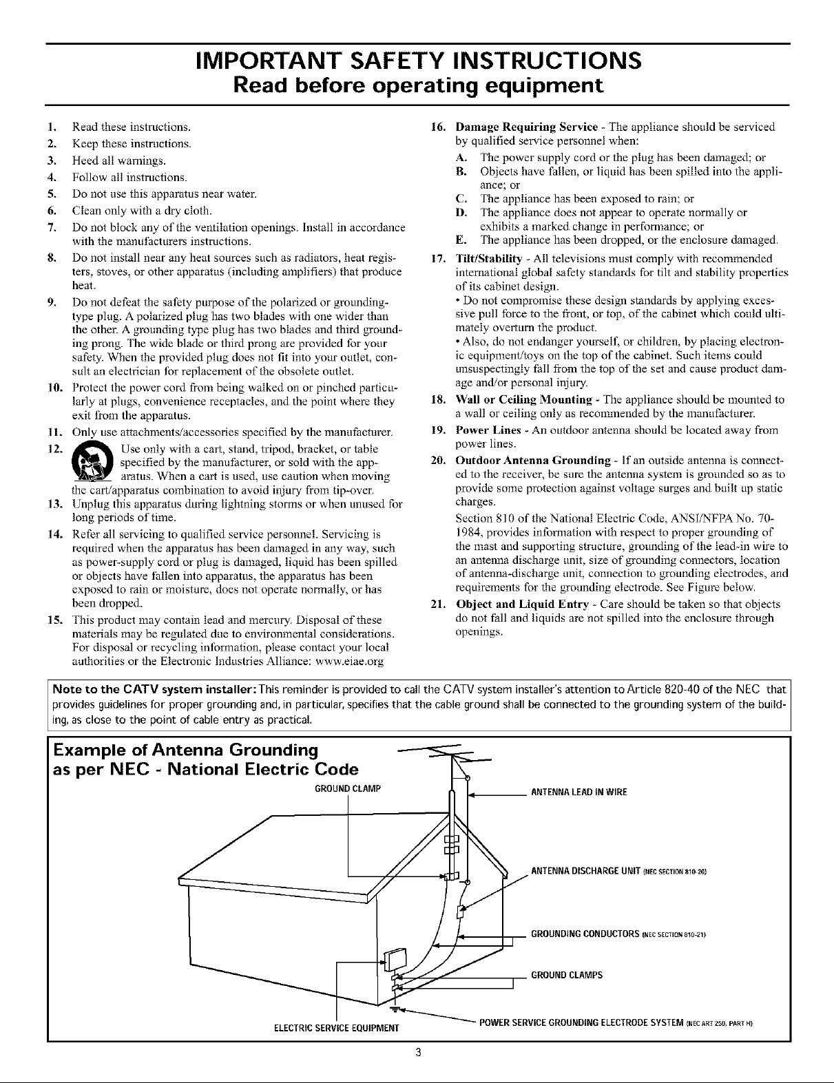
Note to the CATV system installer:This reminder is provided to call the CATV system installer's attention to Article 820-40 of the NEC that
provides guidelines for proper grounding and, in particular, specifies that the cable ground shall be connected to the grounding system of the build-
ing, as close to the point of cable entry as practical.
Example of Antenna Grounding
as per NEC - National Electric Code
GROUNDCLAMP ANTENNALEADINWIRE
ANTENNADISCHARGEUNIT{NEC SECTION 810 20)
GROUNDINGCONDUCTORS (NEC SECTION 830 21}
GROUNDCLAMPS
ELECTRICSERVICEEQUIPMENT _ POWER SERVICEGROUNDINGELECTRODESYSTEM(NECART256,PARI14)
Page 4
INTRODUCTION
Welcome/Registration of Your TV .................... 2
Safety/Precautions .............................. 2 3
Features ........................................ 5
_ AUDIO/VIDEO INPUT JACKS
.lack Panel descriptions and required cables ....... 6
Using the AV I input Jacks ......................... 7
Using the AV 2 input Jacks ......................... 8
Using the Side Input Jacks .......................... 9
Using the AV 3 Input Jacks ........................ 10
Using the AV 4 Input Jacks ........................ 11
Using the Component Video Input Jacks (CVI) ......... 12
Using the S-Video input Jack ....................... 13
Using the Monitor Output Jacks ..................... 14
Using the Audio Output Jacks ...................... 15
PICTURE MENU CONTROLS
Adjusting the Contrast Control ............... 16
Adjusting the Brightness Control .................... 16
Adjusting the Color Control ........................ 16
Adjusting the Sharpness Control .................... 16
Adjusting the Tint Control ......................... 16
How to set the Color Temp Control .................. 16
How to use the Pixel Plus (Digital Processing) Control ., .17
How to set the Dynamic Contrast Control ............. 18
How to use the DNR Control ....................... 19
How to use the Color Enhancement Control ........... 20
How to use the Auto Picture Control ................. 21
How to set the Picture Format Control ................ 22
_ SOUND MENU CONTROLS
Adjusting the TV Volume
(and Headphone Volume) .......................... 23
Adjusting the TV Equalizer Control .................. 24
How to use the Sound Mode Control ................. 25
How to use the Alternate Audio Control ............... 26
How to set the TV for Stereo programming ............ 27
How to use the 3D Surround Effect Control ............ 28
How to use the AVL (Automatic Volume Leveler) Control ,29
How to use the Delta Volume Control ................ 30
How to use the Auto Sound Control .................. 31
Using the Lock After Control ....................... 37
How to block programming using the TV Ratings Lock
Controls ....................................... 38
How to block programming using the Movie Ratings
Controls ....................................... 39
Editing channels with the Channel Remove Control ...... 40
Using the Antenna Attenuator Control ................ 41
_ SPEAKER MENU CONTROLS
Using the Test Tone and Speaker Trim Controls.. ,42
How to turn the Center Mode and Surround Speakers
Controls on .................................... 43
_ GENERAL MENU CONTROLS
How to use the Menu Background Control ...... 44
Using the Surf Control (Channel Surf) ................ 45
How to use the Dual Screen Format Control ........... 46
How to use the Multipip Control .................... 47
How to use the Freeze Control ...................... 48
How to Reset the AV Setting ....................... 49
Using the Tilt Adjust Control ....................... 49
How to Minimize or Maximize the Onscreen Display .... 50
How to set up the Timer Zone and Daylight
Savings Controls ................................ 50
How to change your PIN (Personal Identification Number)
for AutoLock features ............................ 51
How to Label the AV Sources ...................... 52
_ REMOTE CONTROL RELATED FEATURES
Using the Active Control .................... 53
How to use the Zoom Control ...................... 53
Using the Remote Control with accessory devices
Code-Entry Method ............................. 54
Search Method ................................ 55
Direct-Entry Code list for accessory devices ......... 56-57
Remote Control VCR Specific Button ................ 58
IMPORTANT INFORMATION
Care and Cleaning ......................... 59
Troubleshooting ................................. 59
Glossary of terms ................................ 60
Index ......................................... 61
Factory Service Locations ....................... 62-63
Limited Warranty ................................ 64
D FEATURE MENU CONTROLS
How to use the Closed Captions Controls ....... 32
How to use the Sleeptimer Control .................. 33
How to use the On-Timer Control ................... 34
Using the Channel List Control ..................... 35
How to use the Channel Lock Control ................ 36
Refer to the simple Quick Use and Setup
Guide (supplied with yourTV) for details
on Basic Connections, Remote Control
Operation, Language and Auto Program.
Page 5
Active Control TM continuously measures aod corrects all incom-
ing signals/o help provide/he best picture quality. This fea/ure
monitors aod corrects both the sharpness control and noise
reduction control,
Audio/Video Jack Panel allows direct connections with VCRs,
DVDs, High Definition Receivers or other devices, providing
quality TV picture and sound playback.
Audio Volume Leveler (AVL) Control keeps/he TV sound a/
ao even level. Peaks and valleys/hat occur during program
changes or commercial breaks are reduced, making for a more
consistent, comfortable sound.
Channel Lock allows you to block the viewing of certain chan-
nels or programs with certain ratings if you do not waut your
children to view inappropriate materials,
Auto Programming scaos (when activaled) for all available
channels from regular aotenna or cable signals mad stores only
active broadcast stations in the TV's memory,
AutoPicture TM allows you to change the picture settings (colol;
tint, contrast, etc.) for various types of programming, such as
sports, movies, multimedia (games), or weak signals with the
push of one button. Selections include, Personal, Rich, Natural,
Sof/, Multimedia, or Eco.
AutoSound TM allows you to change to different faclory pre-
defined audio settings mad a personal control that you set accord-
ing to your own preferences/hrough the onscreen Sound menu.
The five factory-set controls (Personal, Speech, Music, Movie,
mad Multimedia) enable you to tailor the TV sound so as to
enhaoce/he particular programming you are watching.
Channel Remove allows you Io delete channels from/he list
stored in the TV's memory, Channel Remove makes it easy to
limit the number of channels that ale available to you when you
press the Channel (+) or @) bu.ons on your remo/e control,
Closed Captioning allows the viewer/o read TV program dia-
logue or voice conversations as onscreen text.
Dynamic Contrast helps to sharpen the picture quality by
improving the contrast between the darkest and brighlest parts of
the picture,
Pixel Plus TM (or Digital Processing) gives a choice of two dif-
ferent scanning techniques Progressive Scao or Pixel Plus.
Progressive Scan doubles the number of picture lines, elimi-
nating line flicker and providing a jilter-free picture.
Pixel Plus TM improves the appearance of onscreen motion.
The number of picture lines are increased along with the
number of pixels per line, giving normal broadcast signals,
DVD reproduction or Digital TV signals, unparalleled sharp-
ness and depth. Gives the viewer near High Definition and
natural looking detail without the High Definition signal.
Infrared Remote Control works your TV mad other remote-
controlled devices, such as VCRs, DVD players, cable convert-
ers, salelli/e receivers_ etc.
Onscreen Menu shows helpful messages mad instructions for
setting TV feature controls (can be viewed in English, French, or
Spanish).
Sleep Timer automatically turns the TV OFF af/er a set amount
of time that you choose.
Standard Broadcast (VHF/UHF) or Cable TV (CATV) chan-
nel capability allows for viewing by antenna or cable.
Stereo capability, including a built-in audio amplifier and twin-
speaker syslem, allows for the reception of TV programs broad-
cast in stereo sound.
Surf Button allows you to easily switch among only/he chan-
nels/hat are ofiuterest to you (the ones/hal you have pro-
grammed into the TV's Surf control/hrough the onscreen menu).
Surf allows 2 chaonel surfing or 9 chaonel surfing.
Timer allows you Io set your TV to turn itself ON and OFF
once or daily like ao alarm clock.
As you unpack your TV, please note the included items:
Directionsfi_r Use manual (contains safety-tip, clean-
ing and Factory Service Center location information)
Warranty Registration Card
Remote Control (with supplied batteries for use)
Quick Use Guide to help you set up your new TV.
Please take a few minutes to complete your registration
card. The serial number for the TV is on the rear of the set.
For your future reference, please write down the serial and
model number of this television in the space provided on the
cover of this manual. (In the unlikely event you should need
to place a service call, these numbers will be needed.)
Your new television and its packing contain materials that
can be recycled and reused. Specialized companies can recy-
cle your product m increase the amount of reusable materials
and minimize the amounts that need to be properly disposed.
Your product also uses batteries that should not be thrown
away when depleted, but should be handed in and disposed of
as small chemical waste.
When you replace your existing equipment, please find out
about the local regulations regarding disposal of your old tel-
evision, batteries, and packing materials.
As an Energy Star@ Partner, Philips Consumer
Electronics has determined this product meets
the Energy Star_) guidelines for energy efficien-
cy. Energy Star(l_)is a U.S. registered mark. Using products
with the Energy Stal,o) label can save energy. Saving energy
reduces air pollution and lowers utility bills.
Active Control, AutoPicture, AutoSound, Pixel Plus are
trademarks of Philips Consumer Electronics Company.
Copyright 2002 Philips Consumer Electronics.
Page 6

Ttnpe television is equipped with external
ut and outputjacks./br use with optional
accessol 3, devices such as Home entertainment
Receiver.s,, VCRs, DVD Playe_; Gaming Units,
Video Cameras, etc. 77wjbllowing gives a bri_ff
explanation of the dii_rent types ofiacks avail-
able and the type of cables needed to make
connectioRs.
% _ RI_ - Cable/Antenna Input connec-
tion jack.
AV 1 IN - Audio/Video connection jacks
including Component Video inputs,
AV 2 IN - Audio/Video Input connection
jacks including S-Video connections.
AV 3 IN - Component Video, VGA
(RGB), and Audio input connection
jacks.
AV 4 IN - High Definition Component
5
Video and Audio Input connection jacks,
Monitor Out - Audio/Video Output
6
connection jacks (TV tuner signal only),
Audio Out - Audio connections for
home entertainment receivers and exter-
7
nal speakers.
SIDE -Audio/Video Input jacks include
a S-Video jack, plus a Headphone jack
located on the side of the cabinet,
Located on the back of theTV
[ v,,,,, .n,g
Located on the side of theTV
Cable Descriptions:
@@
A 75-ohm coaxial cable connects signals
from an antenna or a cable TV company
to the antenna jack on the back of the TV.
Coaxial cables use "F'" conneck?rs,
A two-way signal splitter enables you to
take a single antenna or cable TV signal
and supply it to two different inputs,
A 300- to 75-ohm twin-lead adapter
accepts the antenna cables (called twin-
lead wires) from an antenna, allowing you
to connect the antenna signal to the TV,
A S-Video cable provides better picture
performance than regular (composite)
video connections,
S-Video cables can be used only with S-
Video-compatible accessory devices. You
must also connect the left and right audio
cables to the AV 2 Audio in jacks because
the S-Video jack carries only the picture
signal, not the sound,
Yellow - Video
White - Audio Left
Red - Audio Right
Video and audio cables with standard
RCA (phono) connectors connect the
video and audio jacks of accessory
devices such as VCRs and DVD players
to the jacks on the TV.
These connectors are usually color coded.
The jacks on your TV are also color
coded to match the colors of the connec-
tors. Yellow for video (composite) and
Red and White for the right and left audio
channels, The video cables used to con-
nect component video or RGB (high-reso-
lution) jacks are color coded red, green,
and blue.
A VGA (HD15) cable makes a VGA
(RGB) connection to the HD INPUT-AV
4 jack on the rear of the TV.
Page 7
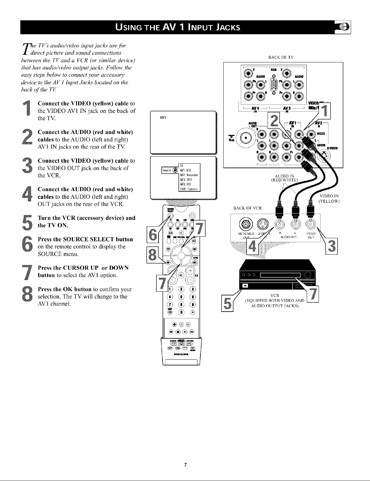
_d e YVIv audioA4deo input jacks are Jot
irect picture and sound connections
between the TV and a VCR (or similar device)
that has audio/video output jacks, fbllow the
ea._y steps below to connect your accessory
device to the A V ! htput Jacks located on the
back of the TE
Connect the VIDEO (yellow) cable to
the VIDEO AVI IN jack on the back of
the TVI
Connect the AUDIO (red and white)
cables to the AUDIO (lefl and right)
AVI IN jacks on the rear of the TVI
Connect the VIDEO (yellow) cable to
the VIDEO OUT jack on the back of
the VCR.
AVI
BACK OF TV
y q i RDB Y_ I
AUDIO O AUDIO
®,,®,®
&®, o-®,®
AUDIO
AUDIO IN
Connect the AUDIO (red and white)
cables to the AUDIO (lefl and right)
OUT jacks on the rear of the VCR,
Turn the VCR (accessory device) and
the TV ON.
Press the SOURCE SELECT button
on the remote control to display the
SOURCE metal
Press the CURSOR UP or DOWN
button to select the AVI option,
Press the OK button to confirm your
selection, The TV will change to the
AVI channel.
®®®
®®®
@@®@
BACK OF VER
VCR
(EQUIPPED Wr[H VIDEO AND
AUDIO OUTPUT JACKS)
R L VIDEO
AUDEO OUT OUT
VIDEO IN
(YELLOW)
Page 8
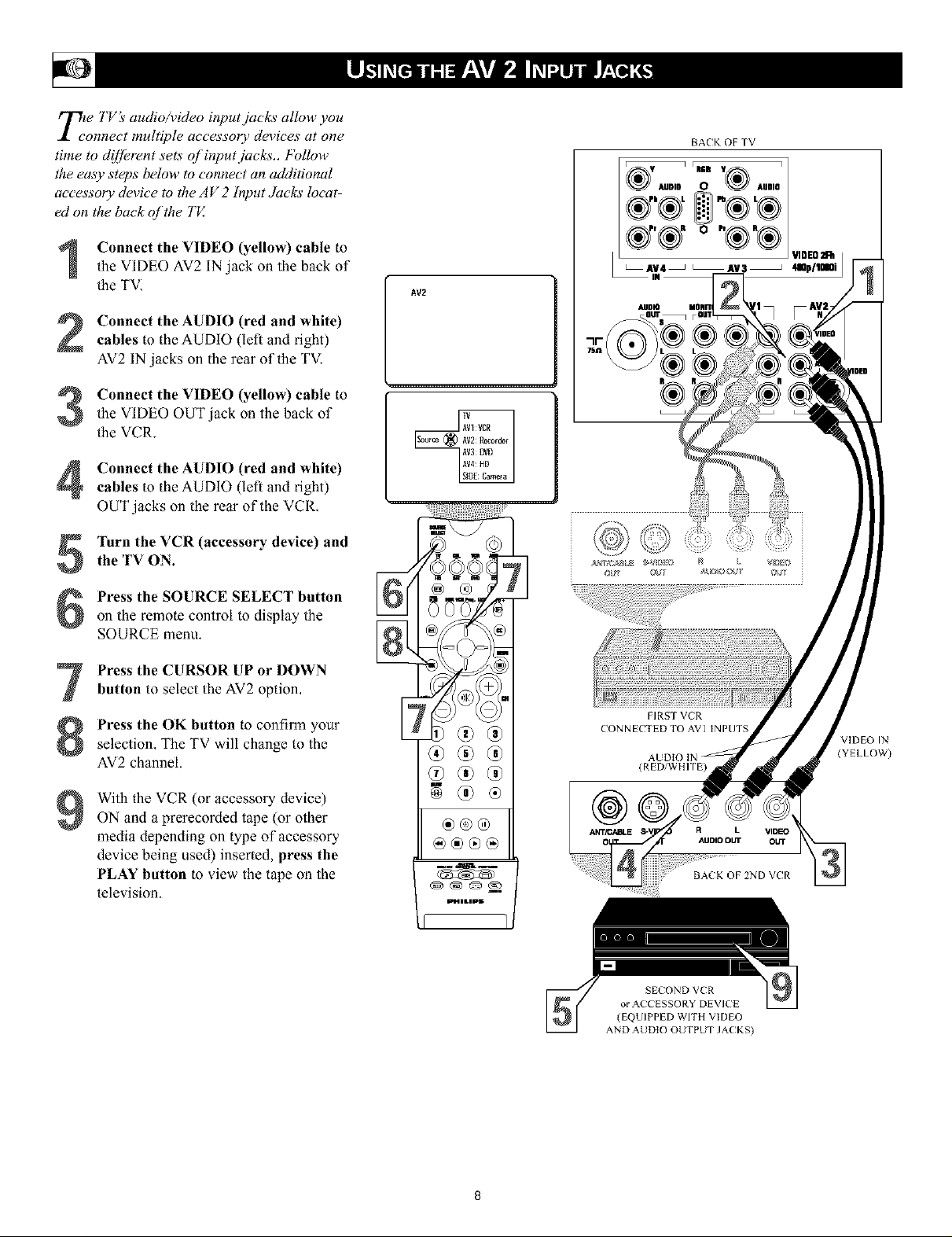
TLte )'Viv audio/video input jacks allow you
onnect multiple accessol T devices at one
time to d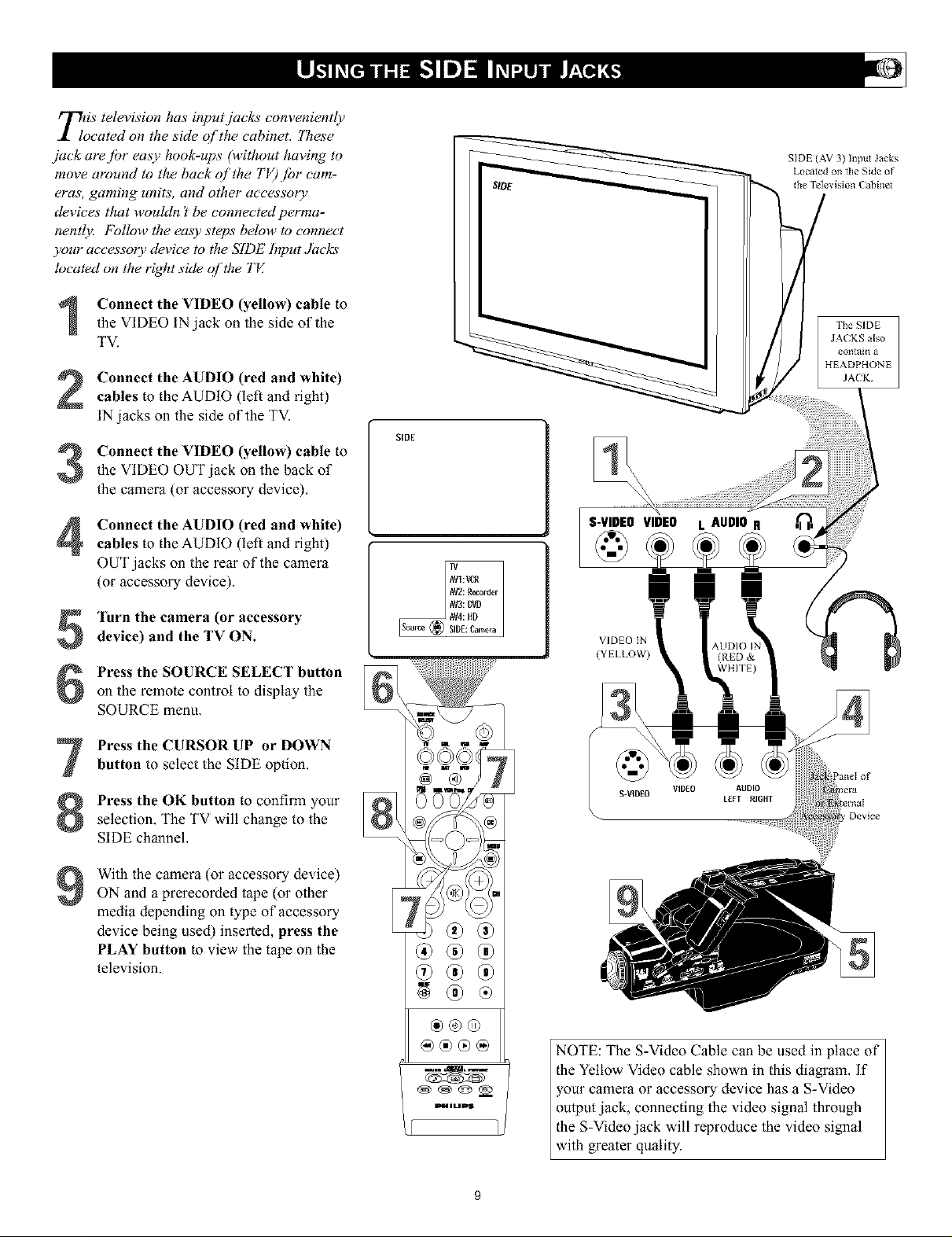
TioiS television has input jacks conveniently
cated on the side of the cabinet. "lTwse
jack are fbr easy hook-ups (without having to
move around to the back of the TV) jbr cam-
eras, gaming units, and other accessory
devices that wouldn't be connected perma-
nently: Follow the easy steps below to connect
),our accessory device to the SIDE Input Jacks
located on the right side qf the "I'V.
Connect the VIDEO (yellow) cable to
the VIDEO IN jack on the side of the
TV.
Connect the AUDIO (red and white)
cables to the AUDIO (left and right)
IN jacks on the side of the TV.
Connect the VIDEO (yellow) cable to
the VIDEO OUT jack on the back of
the camera (or accessory device),
Connect the AUDIO (red and white)
cables to the AUDIO (lefl and right)
OUT jacks on the rear of the camera
(or accessory device).
SIDE (AV 3) Input Jacks
Located on tlle Side of
the Tele\ ision E abinet
The SIDE
JA(KS also
¢olltai_l a
HEADPHONE
JACK¸
SIDE
"K
S-VIDEOVIDEO L AUDIO R
Turn the camera (or accessory
device) and the TV ON.
Press the SOURCE SELECT button
on the remote control to display the
SOURCE menu,
Press the CURSOR UP or DOWN
button to select the SIDE option.
Press the OK button to confirm your
selection, The TV will change to the
SIDE channel,
With the camera (or accessory device)
9
ON and a prerecorded tape (or other
media depending on type of accessory
device being used) inserted, press the
PLAY button to view the tape on the
television.
®®
0o®0o
®®@
@@®@
_mLmD$
VIDEO IN
(YELLOW)
S-VIDEO
VIDEO AUDIO
LEFT RIGHT
Device
NOTE: The S-Video Cable can be used in place of
the Yellow Video cable shown in this diagram, if
your camera or accessory device has a S-Video
output jack, connecting the video signal through
the S-Video jack will reproduce the video signal
with greater quality.
Page 10
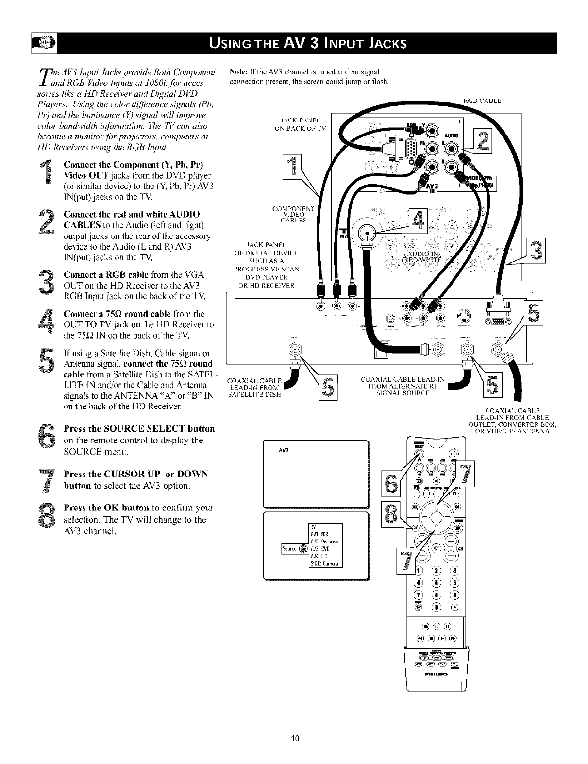
T_e A V3 hTput Yacks plvvide Both Component
nd RGB _'deo hTputs at 1080i, fbr acces-
sories like a liD Receiver and Digital DVD
Players'. Using the color d!fference signals (Pb,
Pr) and tile luminance (Y) signal will improve
color bandwidth inibrmation. _he TV can also
become a monitorjbr projectors, computers or
HD Receivers using the RGB Input.
Connect the Component (Y, Pb, Pr)Video OUT jacks from/he DVD player
(or similar device) to/he (Y,Pb, Pr)AV3
IN(put) jacks onthe TV.
Connect the red and white AUDIO
CABLES to the Audio (left and right)
ou/put jacks on/he rear of the accessory
device m/he Audio (L and R) AV3
IN(put) jacks on the TV.
Connect a RGB cable from/he VGA
OUT on/he HD Receiver to the AV3
RGB Input jack on the back oDhe TV.
Connect a 75_ round cable from/he
OUT TO TVjack on the HD Receiver to
/he 75f_ IN on/he back of the TV.
]fusing a Satelli/e Dish. Cable signal or
Anlenna signal, connect the 75£2round
5
cable from a Satellile Dish/o the SATEL-
LITE IN and/or/he Cable and Anlenna
signals/o/he ANTENNA "A" or "B" IN
on/he back of the HD Receiver.
Press the SOURCE SELECT button
on the remote control to display the
SOURCE menu.
Note: If the AV3 channel is tuned and no signal
connection present, the screen could jump or flash.
JACK PANEL
ON BACK OF TV
(OMPONENT
VIDEO
CABLES
JACK PANEL
OF DIGITAL DEVICE
SU(H AS A
PROGRESSIVE SCAN
DVD PLAYER
OR HD RECEIVER
COAXIAL CABLE LEAD-IN
LEAD-IN FROM
COAXIAL (!ABLE
SATELLP[ E DISH
AV3
FROM ALTERNA'I E RF
SIGNAL SOURCE
RGB (!ABLE
COAXIAL CABLE
LEAD-IN FROM CABLE
OUTLE% CONVERTER BOX,
OR VHF/UHF ANTENNA
Press the CURSOR UP or DOWN
button to select the AV3 option.
Press the OK button to confirm your
selection. The TV will change to the
AV3 channel.
®®®
10
Page 11

T]npe A V4 Input Jucks provide Component _'deo
uts at 1080i, jbr accessories like a HD
Receiver and Digital DVD Players'. Using the
color d![Jerence signals (Pb, Pr) and the lumi-
nance ( Y) signal will improve color bandwidth
i_fi)rmation.
Conned the Component (Y, Pb, Pr)
Video OUT jacks from the DVD player
(or similar device) to/he (Y,Ph, Pr) AV4
IN(put) jacks on/he TV.
Connect the red and white AUDIO
CABLES to/he AUDIO (left and right)
OUT(pu/) jacks on the rear of/he accesso-
ry device/o/he Audio (L and R) AV4
IN(put) jacks on/he TV,
Press the SOURCE SELECT buttonon the remote control to display the
SOURCE menu.
Note: If the AV4 channel is tuned and no signal con-
nection present, the screen could .iump or flash.
JACK PANEL
ON BAEK OF TV
AUDIO
VIDEO2Fh jgOp/lmOi
IN
Press the CURSOR UP or DOWN
button to select the AV3 option.
Press the OK button to confirm your
selection, The TV will change to the
AV3 channel,
]'urn the TV and the DVD (or digitalaccessory device) ON.
Press the PLAY button on the DVD (ordigitalaccessory device) to view/he pro-
gram on the television.
AV4
JACK PANEL
OF DIGITAL DEVICE SUCH
AS A DVD PLAYER
EQUIPPED Wr[H
COM PONEN'I VIDEO
OUTPUTS
®®®
®®®
@®®@
11
Page 12
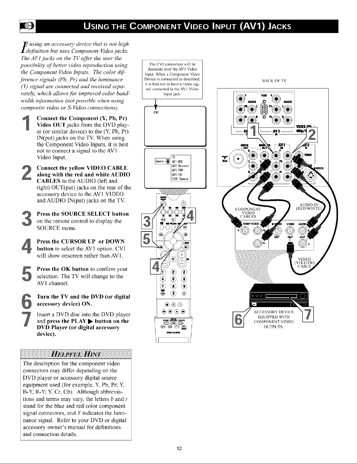
L'using an accesso O, device that is not high
efinition but uses Component Video jacks.
77te AVl jacks on the TV offer the user the
possibility of better video reproduction using
the Component Video Inputs. 77w color d!/:
/erence signals (Pb, PO and the luminance
(Y) signal are connected and received sepa-
ratel); which allows./or intproved color band-
width inf!)rmation (not possible when using
composite video or S-Video connections).
rkm CVI connection will be
domhlate over file AVI Video
Input¸ When a Component Video
Device is connected as described,
it is best not to have a video sig-
naI connected to tile AVI Video
Input jack¸
BACK OF TV
o
Connect the Component (Y, Pb, Pr)Video OUT jacks from the DVD play-
er (or similar device) io the (Y, Pb, Pr)
IN(put) jacks on the TV. When using
the Component Video inputs, it is best
not io connect a signal io the AVI
Video Input.
Connect the yellow VIDEO CABLE
along with the red and white AUDIO
CABLES to the AUDIO (left and
right) OUT(put)jacks on the rear of the
accessory device to the AVI VIDEO
and AUDIO IN(put)jacks on the TV,
Press the SOURCE SELECT button
on the remote control to display the
SOURCE menu,
Press the CURSOR UP or DOWN
button to select the AVI option. CVI
will show onscreen rather than AVI.
Press the OK button to confirm your
selection, The TV will change to the
AVI channel.
VIDEO
®®®
Turn the TV and the DVD (or digital
accessory device) ON.
insert a DVDdisc into theDVDplayer
and press the PLAY l_button on the
DVDPlayer (or digital accessory
device).
The description for the component video
connectors may differ depending on the
DVD player or accessory digital source
equipment used (for example, Y,Pb, Pr; Y,
B-Y, R-Y_ Y,Cr, Cb). Although abbrevia-
tions and terms may vary, the letlers b and r
stand for the blue and red color component
signal connectors, and Y indicales the lumi-
nance signal. Refer to your DVD or digital
accessory owner's manual for definitions
and connection details.
®@®
pl, i i tl iP_
ACCESSORY DEVICE
EQUIPPED WITH
COMPONENT VIDEO
OUTPUTS
12
Page 13
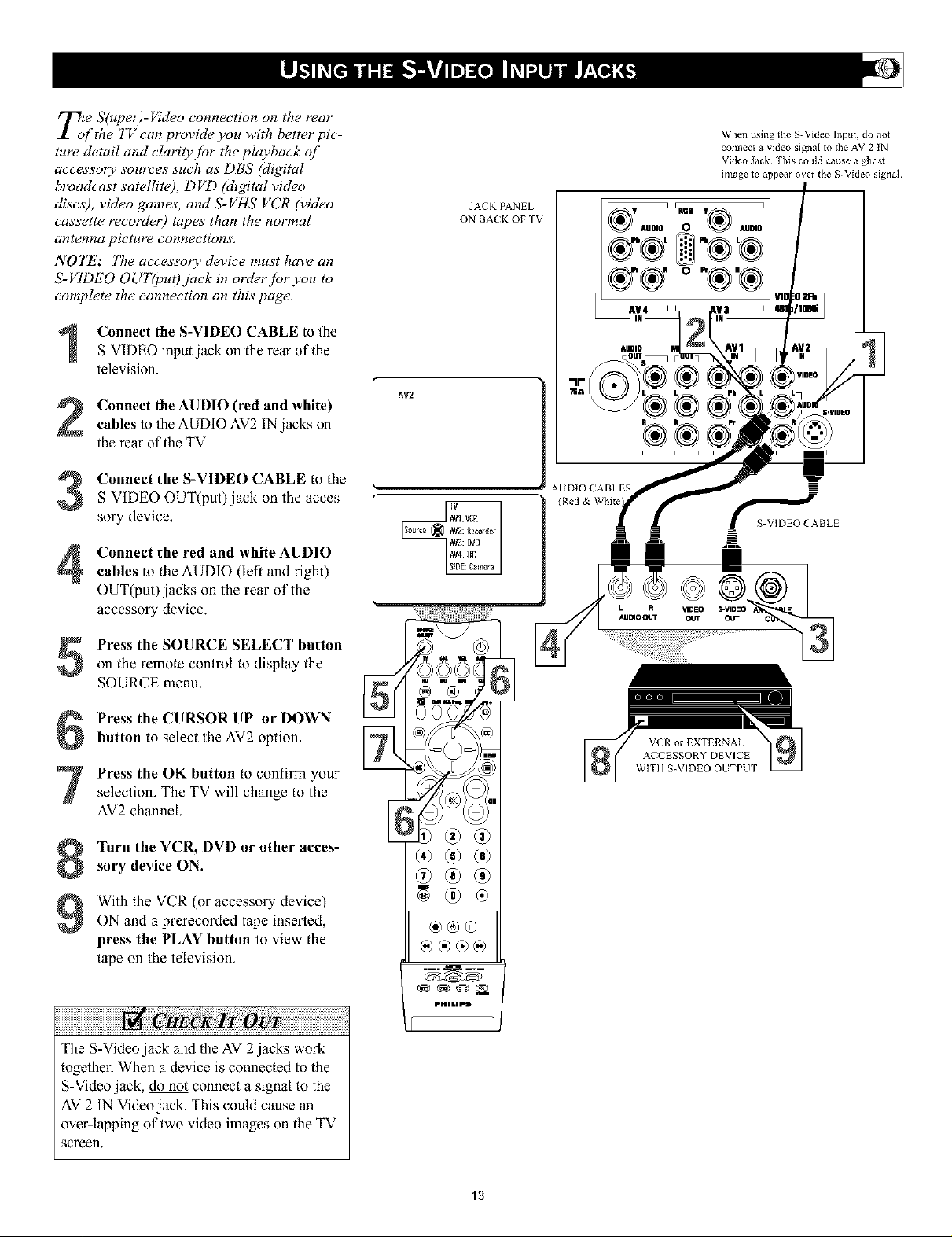
Tote S(uper)-Video connection on the rear
/the TV can provide you with better pic-
ture detail and clarity./br the playback of
accesso O, sources such as DBS (digital
broadcast satellite), DVD Migital video
discs), video games, and S-VHS VCR (video
cassette recorde 0 tapes than the normal
antenna pi('tuFe connections,
NOTE: 77w accessory device must have an
S-VIDEO OUT(puO jack in order.fbr you to
complete the connection on this page.
JACK IZa,NEL
ON BACK OF TV
When using the S-Video Input, do not
connect a video signal to tile AV 2 IN
Video Jack¸ Tl_is could cause a ghost
image _o appear over _he S-Video signal¸
"®_oI !
®*®. oo®.®
_AV4 _
Connect the S-VIDEO CABLE to the
S-VIDEO input jack on the rear of the
television.
Connect the AUDIO (red and white)
cables to Ihe AUDIO AV2 INjacks on
the rear of the TV.
Connect the S-VIDEO CABLE to the
S-VIDEO OUT(put)jack on the acces-
sory device,
Connect the red and white AUDIO
cables to the AUDIO (left and right)
OUT(put) jacks on the rear of the
accessory device.
Press the SOURCE SELECT button
on the remote control to display the
SOURCE menu,
Press the CURSOR UP or DOWN
button to select the AV2 option,
Press the OK button to confirm your
selection, The TV will change to the
AV2 channel.
&UDIQ
AV2
AUDIO CABLES =
VER or EXTERNAL
A( CESSORY DEVICE
WITH S-VIDEO OUTPUT
Turn the VCR, DVD or other acces-
sory device ON.
With the VCR (or accessory device)
ON and a prerecorded tape inserted,
press tile PLAY button to view the
tape on the television,
The S-Video jack and the AV 2 jacks work
logether. When a device is connecled to the
S-Video jack, do not connect a signal m the
AV 2 IN Video jack, This could cause an
over-lapping of two video images on the TV
screen.
®®oo
®®@
g®®
®®®
@®®®
13
Page 14
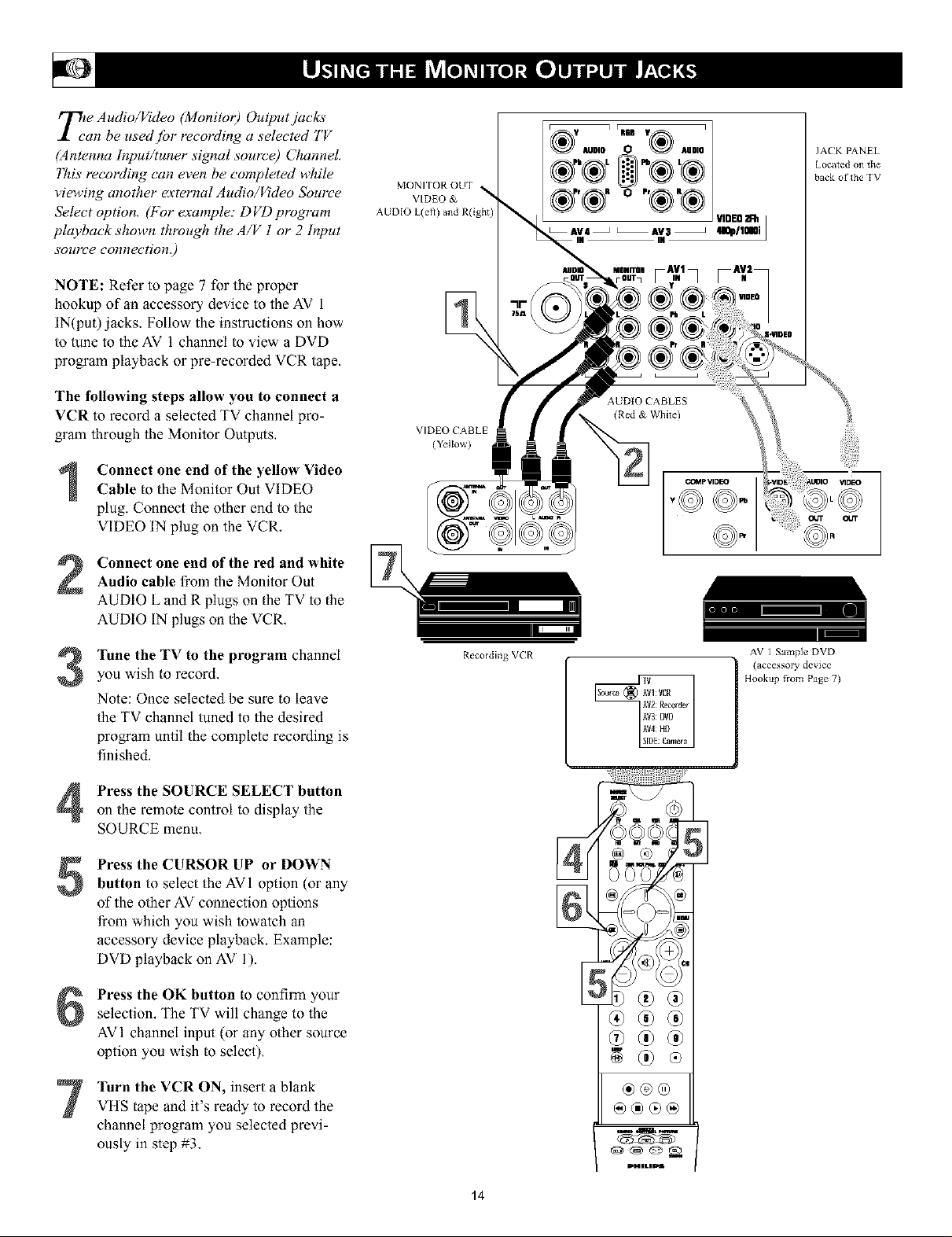
Tt[ Audio/Video (Monito 0 Output jacks
an be used.fbr recording a selected 7'V
(Antenna Input/tuner signal source) Channel.
lhis recording can even be completed while
viewing another external Audio/Video Source
Select option. (Fnr example: DVD program
playback shown through the A/V ! or 2 Input
sollrce connection 0
NOTE: Refer to page 7 for the proper
hookup of an accessory device to the AV 1
IN(put) jacks. Follow the instmclions on how
to tune to the AV 1 channel to view a DVD
program playback or pre-recorded VCR tape.
The following steps allow you to connect a
VCR to record a selected TV channel pro-
gram through the Monitor Outputs,
Connect one end of the yellow VideoCable to the Monitor Out VIDEO
plug. Connect the other end to the
VIDEO IN plug on the VCR,
MONr[OR OUT
VIDEO &
AUDIO L(efl) and R(ight)
VIDEO (!ABLE
(YelIow)
AUDIO 0 AUDIO
o"®'®
IN
(Red & White)
JACK PANEL
Located on the
back of the TV
VIDEO2AI i_AV3 _ qop/loaoi
Connect one end of the red and whiteAudio cable from the Monitor Out
AUDIO L and R plugs on the TV to the
AUDIO IN plugs on the VCR,
Tune the TV to the program channel
3
you wish to record,
Note: Once selecled be sure to leave
the TV channel luned to the desired
program until the complete recording is
finished,
Press the SOURCE SELECT button
4
on the remote control to display the
SOURCE menu,
Press the CURSOR UP or DOWN
5
button to select the AVI option (or any
of the other AV connection options
from which you wish towatch an
accessory device playback, Example:
DVD playback on AV 1).
Press the OK button to confirm your
selection, The TV will change to the
AVI channel input (or any other source
option you wish to select),
Recording VCR
AV 1 Sample DVD
(accessory device
Hookup fl'om Page 7)
Turn the VCR ON, insert a blank
VHS tape and it's ready to record the
channel program you selected previ-
ously in step #3.
®®®
®®®@
pl, mmLm_
14
Page 15
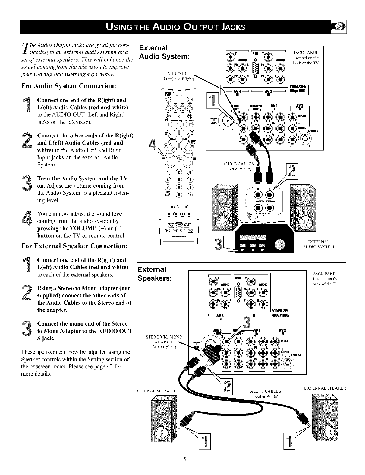
Tile Audio Output jacks are greatjbr con-
ecting to an external audio system or a
set qf external ._peakers. ?'his will enhance the
sound comingj?om the television to improve
your viewing and listening e_xperience,
For Audio System Connection:
Connect one end of the R(ight) andL(eft) Audio Cables (red and white)
to the AUDIO OUT (Left and Right)
jacks on the telexision.
Connect the other ends of the R(ight)
and L(eft) Audio Cables (red and
white) to the Audio Left and Right
Input jacks on the external Audio
System,
Turn the Audio System and the TV
on. Adjust the volume coming from
the Audio System to a pleasant listen-
ing level.
YOUcan now adjust the sound level
coming from the audio system by
• • q_
pressing the VOLUME ( ) or (-)
button on the TV or remote control.
For External Speaker Connection:
External
Audio System:
AU DIO OUT
L(eff) and R(igbt)_
@ ® @
@@@
[DID ILI PB
AUDIO O AUOIO Located on file
_,®L +,,®L® backortheWV
®
_1 JACK PANEL
/®+®,o"®'®/
AUDIO CABLES
(Red & \Vhite)
®®
®®
EXTERNAL
AUDIO SYSTEM
Connect one end of the R(ight) and
L(eft) Audio Cables (red and white)
to each of the external speakers,
Using a Stereo to Mono adapter (not
supplied) connect the other ends of
the Audio Cables to the Stereo end of
the adapter.
Connect the mono end of the Stereo
to Mono Adapter to the AUDIO OUT
S jack.
These speakers can now be adjusted using the
Speaker controls within the Setting section of
the onscreen menu, Please see page 42 for
more details,
External
Speakers:
STEREO TO MONO
ADAPTER
EXTERNALSPEAKER
AUDIO (ABLES
JA(K PANEL
Located on the
back of tbe "IV
EXTERNALSPEAKER
15
Page 16
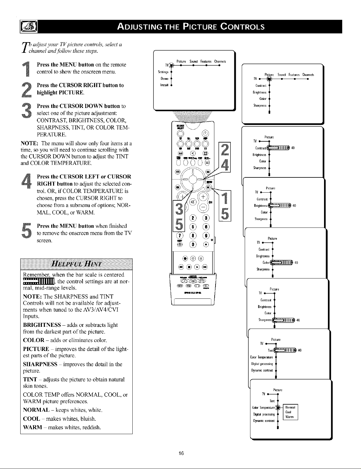
TbdlacO'ust your TV picture controls, select a
annel and fi_llow these steps.
Picture Sound Features Channels
Press the MENU button on the remotecontrol to show the onscreen menu.
Press the CURSOR RIGHT button to
highlight PICTURE,
Press the CURSOR DOWN button to
3
select one of the picture adjustment:
CONTRAST, BRIGHTNESS, COLOR,
SHARPNESS, TINT, OR COLOR TEM-
PERATURE.
NOTE: The menu will show only four items at a
time, ,soyou will need to continue scrolling with
the CURSOR DOWN button to adjust the TINT
and COLOR TEMPERATURE.
Press the CURSOR LEFT or CURSOR
4
RIGHT button toadjustthe selected con-
trol. OR, if COLOR TEMPERATURE is
chosen, press the CURSOR RIGHT to
choose from a submenu of options; NOR-
MAL, COOL, or WARM.
to remove the onscreen menu from the TV
Press the MENU button when finished
screen.
Settings
Demo
Install
t
Picture Sound Features Channels
Contrast
Brightness
Color
TV = i
Sharpness
Picture
Contrast 40
Brightness
Color
Sha
Remember, when the bar scale is centered
_I111], the control settings are at nor-
mal, mid-range levels.
NOTE: The SHARPNESS and TINT
Controls will not be available for adjust-
ments when tuned to the AV3/AV4/CVI
Inpms.
BRIGHTNESS adds or subtracts light
from the darkest part of the picture.
COLOR adds or eliminates color.
PICTURE improves the detail of the light-
est parts of the picture.
SHARPNESS improves the detail in the
9icture.
TINT adjusts the picture to obtain natural
skin tones.
COLOR TEMP offers NORMAL, COOL, or
WARM picture preferences.
NORMAL keeps whites, white.
COOL makes whites, bluish.
WARM makes whites, reddish.
®@®
IDI[41L I pI[*
Picture
Contrast
grightne_s
Color
Sha 40
16
Page 17
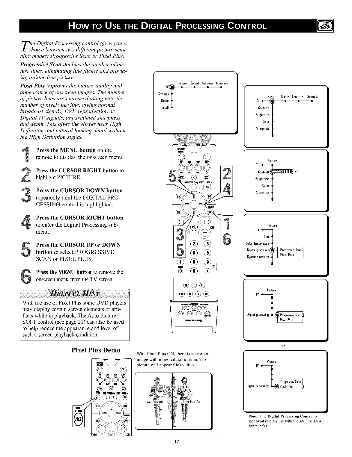
TLl/e Digital Processing control gives you a
hoice between two d!ffLn'ent picture scan-
ning modes: Progressive Scan or Pixel Plus,
Progressive Scan doubles the nmnber q/]vic-
tare lines, eliminating line flicker and provid-
ing a jitterffi'ee picture.
Pixel Plus improw_s the picture quality and
appearance of onscreen images, The number
of picture lines are increased along with the
number qlpixels per line, giving normal
broadcast signals, DVD reproduction or
Digital TV signals, unparalleled sharpness
and depth, 77tis gives the viewer near High
Definition and natural looking detail without
the High Definition signal
Press the MENU button on the
remote to display the onscreen menu.
Press the CURSOR RIGHT button to
highlight PICTURE,
Press the CURSOR DOWN button
repeatedly until the DIGITAL PRO-
CESSING control is highlighted.
Picture Sound FeaturesChannels
41
Picture Sound [eatures Channels
1V_! _ = =
Bdghtnes_
Colsr
Contrast
Sha
Picture
Contrast 40
Brightness
Color
IV_
Sha
Press the CURSOR RIGHT button
to enter the Digital Processing sub-
menu,
Press the CURSOR UP or DOWNbutton to select PROGRESSIVE
SCAN or P[XEL PLUS,
Press the MENU button to remove theonscreen menu from the TV screen.
With the use of Pixel Plus some DVD players
may display certain screen elements or arti-
facts while in playback. The Auto Picture-
SOFT control (see page 21) can also be used
to help reduce the appearance and Levelof
such a screen playback condition,
Pixel Plus Demo
@ @
®®®
PlL'II LIPS
i iI
With Pixel Plus ON, there is a sharper
image with nlore natural motion. The
picture will appeal" flicker fi'ee.
Picture
lint
_1_ Temperature
Dig_l processing Prcoresive Scan]
Dynamic Plxel Plus
Picture
IV
Digital proc'essin_ Progresive Scan_}
Digital peo Pixel Plus
Pixd Plus
OR
Picture
J
J
Note: The Digital Processing Control is
not available f_r use _it}l tile AV 3 or AV 4
input jacks
17
Page 18
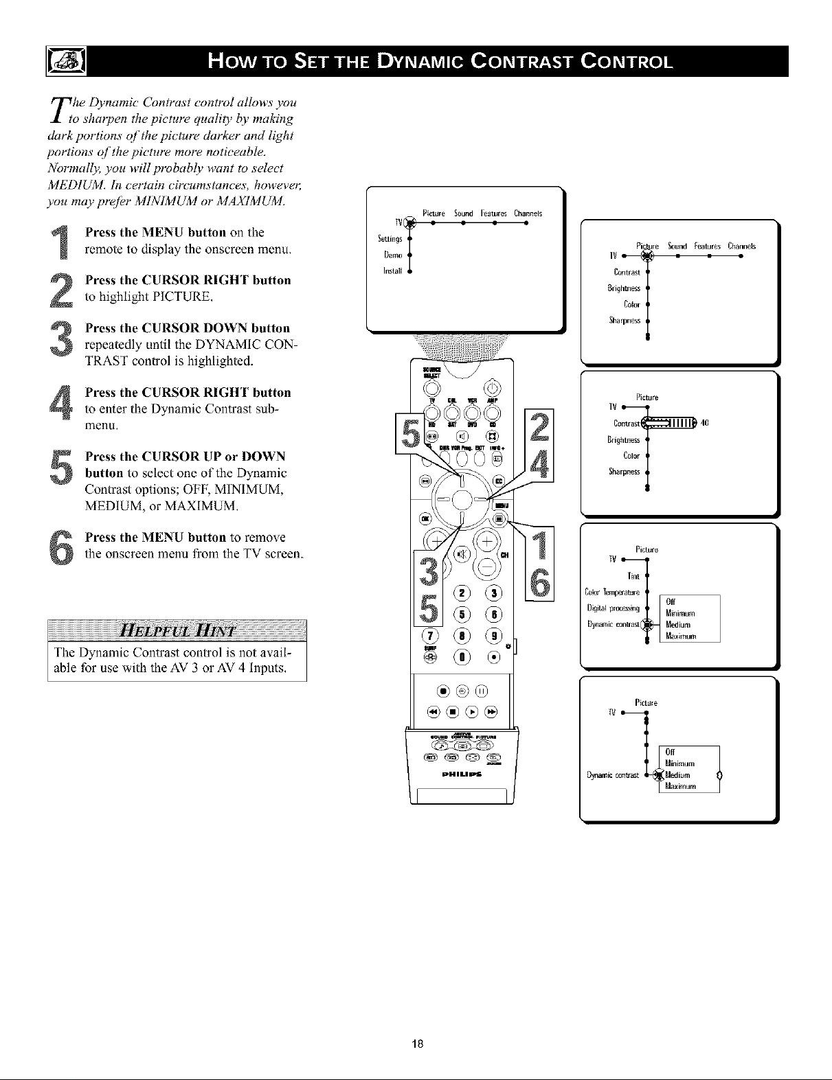
The Dynamic Contrast control allows you
o shmTen the picture quality by making
dark portions of the picture darker and light
portions q/the picture more noticeable.
Normall2; you will probably want to select
MEDIUMI In certain circumstance.s,, howevec
you may prefer MINIMUM or MAX1MUMI
Press the MENU button on the
1
remote to display the onscreen menu,
Press the CURSOR RIGHT button
2
to highlight PICTURE,
Press the CURSOR DOWN button
3
repeatedly until the DYNAMIC CON-
TRAST control is highlighted.
Settings
Demo
Instatl
Picture _ound Features Channels
Pie ure Sound Features Channels
Contrast
Brightness
Cotor
TV _
]ha
Press the CURSOR RIGHT button
to enter the Dynamic Contrast sub-
menu,
Press the CURSOR UP or DOWNbutton to select one of the Dynamic
Contrast options; OFF, MINIMUM,
MEDIUM, or MAXIMUM,
Press the MENU button to remo_ethe onscreen menu from the TV screen.
W _lK _ mP
®@®
PHlUla_
41
Picture
Contrast 40
Brightness
Color
fV_
Sha
Picture
Tint
:oleo TernFerature
Olgit'_v_ng Minimum
Dynamic Medium
Tv bn_ast_ Off
Oynamic contrast Medium
Off
Maximum
Plcture
Minimum
Maximum
18
Page 19
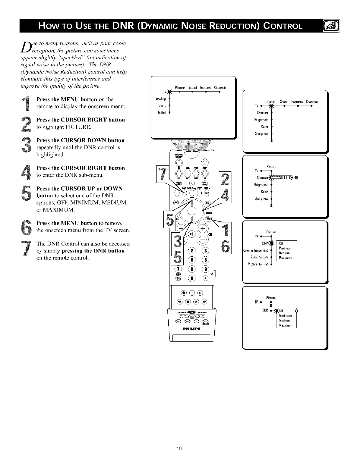
Due to many reasons, such as poor cable
reception, the picture can sometimes
appear slightly "speckled" (an indication of
signal noise in the picture). The DNR
(Dynamic Noise Reduction) control can help
eliminate this type of interjOrence and
improve the quality of the picture.
Press the MENU button on the
remote to display the onscreen menu.
Press the CURSOR RIGHT button
to highlight PICTURE,
Press the CURSOR DOWN button
repeatedly until the DNR control is
highlighted,
SettingsT[}emo
Install
Picture _ound Features Channels
IV_-_
Pilc_fre Soun_ Featares Channels
gri£htness
Corot
C°ntrast I
Sharpness
Press the CURSOR RIGHT button
4
to enter the DNR sub-menu,
Press the CURSOR UP or DOWN
button to select one of the DNR
5
options; OFF, MINIMUM, MEDIUM,
or MAXIMUM.
Press the MENU button to remmethe onscreen menu from the TV screen.
The DNR Control can also be accessed
by simply pressing the DNR button
on the remote control.
iv :L _ _P
©©©©
g®
PHILIPS
61
Picture
Contrast 40
Brightness
Color
Sha
Picture
DNR
_I_ enhar_ent
Autn picture
Picmre f
19
Page 20
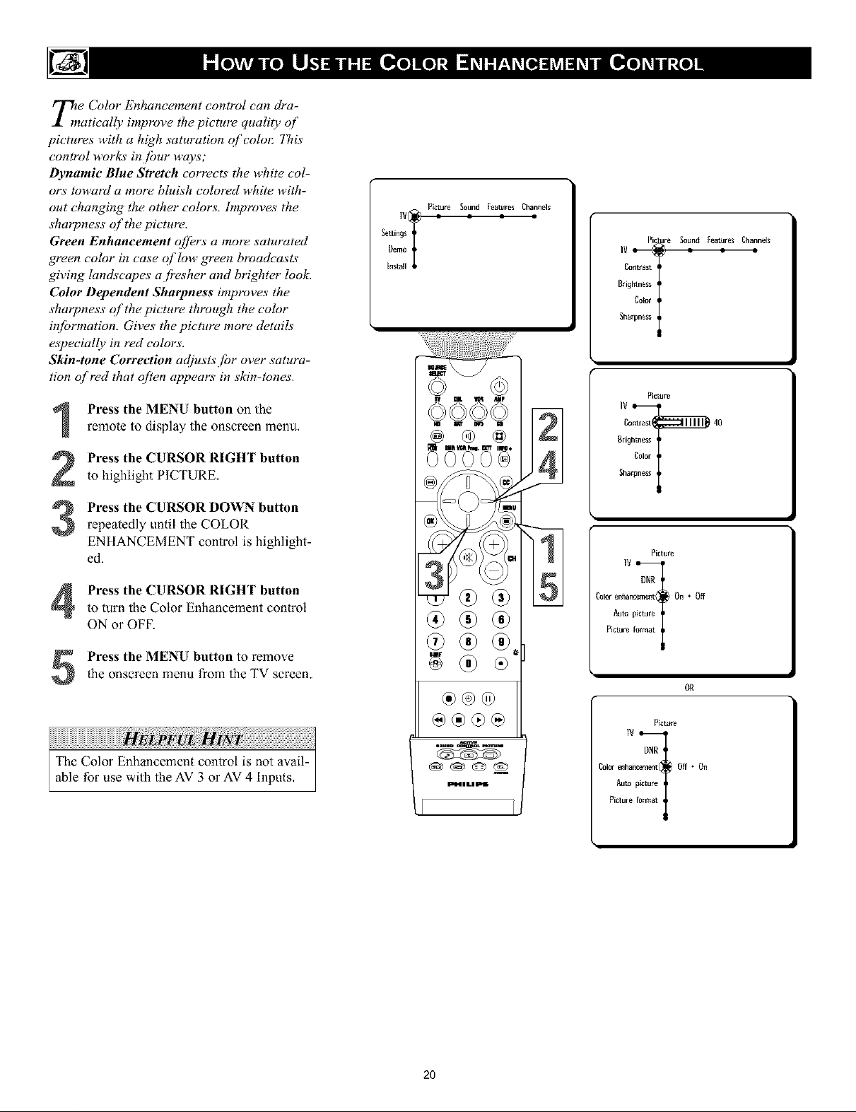
T/f Color Enhancement control can dra-
matically improve the pictmw quality of
pictures with a high saturation of colol: 771is
control works in /hur ways;
Dynamic Blue Stretch corrects the white col-
ors toward a more bhdsh colored white with-
out changing the other colors, hnproves the
sharpness of the picture,
Green Enhancement qffer.s, a more saturated
green color in case qJlow green broadcasts
giving landscapes a/?esher and brighter loolc
Color Dependent Sharpness improve.s, the
sharpness of the picture through the color
in_brmation. Give.s" the picture more details
especially in red color.s,.
Skin-tone Correction at!lusts/br over satura-
tion qf red that often appears in skin-tones.
Press the MENU button on the
remote to display the onscreen menu,
Press the CURSOR RIGHT button
to highlight PfCTURE,
Press the CURSOR DOWN button
repeatedly until the COLOR
ENHANCEMENT control is highlight-
ed.
Press the CURSOR RIGHT buttonto turn the Color Enhancement control
ON or OFF.
SettingsTDemo
[nst_ll
Picture _3und Features Channels
IV_
tit _ StMp
@ ® @
m
Picture Soun_ _ttJres Channels
Brightness
Cator
C°nffa_t
Sha
Picture
Contrast 40
Brightness
,;.©
Color
Sha
I
Picture
DNR
ColOreaharo_m_t On * Off
Aura picture
Picmre [
Press the MENU button to remmethe onscreen menu from the TV screen.
®®®
@®®@
Ec_L-I iLI pff
2O
OR
Picture
DNR
ColOrenhancement Off * On
Auto picture
Picmre [
Page 21

_/_ether you're watching a movie or a
ideo game, your TV has automatic
video control settings that will match with
yollr current progra_#l SOllrce or contenL
AutoPicture TM quickly resets your TV's video
controls fbr a number of d!ffL,rent OTes o1
programs and viewing conditions that you
may" have in your home. 771e Personal
AutoPicture T_asettings are the same as the
PICTURE control adjustments made within
the onscreen menu.
Press the PICTURE button on theremote control. The Auto Picture menu
will appear on the TV screen.
Press the CURSOR DOWN button
repeatedly to select either PERSON-
AL, RICH, NATURAL, SOFT, MUL-
TIMEDIA or ECO picture settings.
Afler your selection is made the
onscreen menu will disappear from the
TV screen within a couple of seconds.
NOTE: The PERSONAL setting and the
PICTURE options within the onscreen menu
are the same. This is theonly option in
AutoPicturc'" that can be changed, To adjust
these settings, use the PICTURE options
within the onscreen menu. All other settings
are set up at the factory during production and
cannot be adjusted.
Auto picture @ Personat 1
Rich
Multlraedla
_Natural
Soft
_ltime(Jia
IAut° picture (_Natural
@
Multimedia
PERSONAL picture settings are based on
your personal choice or viewer conlrol prefer-
ences.
RICH emphasizes very vibrant colors,
(Good choice for AV mode used in a brightly
lit room,)
NATURAL sets picture controls at mid-
level settings for consistent viewing condi-
tions,
SOFT emphasizes warm colors, (Good
choice for dimly lit room. Gives a cinema-
like effect when the light is switched ofl_)
Note: Can also be used with Pixel Plus con-
trol (see page 17) tt_ soften the appearance of
harsh video replay screen elements that can
show with cert_fm types of DVD playback
conditions.
MULTIMEDIA emphasizes soft colors.
(Good choice for playing computer games,
etc,)
ECO reduces Brightness and Contrast set-
tings to low levels as a power consumption
saving measure,
®®®
Auto picture
21
Page 22

you can change the screen.f!)rmat size to
*atch the tA,pe oj]vrogram you're watch-
ing. Select the normal 4.'3 a.spect ratio o1"a
vaHetA, /or wide screen /brmats.
Press the MENU button on the
1
remote to display the onscreen menu,
Press the CURSOR RIGHT button
2
to highlight PICTURE.
Press the CURSOR DOWN button
3
repeatedly until the Picture Format
control is highlighted.
Press the CURSOR RIGHT buttonto enter the Picture Format sub-menu
options.
Press the CURSOR DOWN button
1o select one of the seven screen for-
5
mats, Choose from Automatic, Super
Zoom, 4:3, Movie Expand 4:3, Movie
Expand 16:9, 16:9 Subtitle, or Wide
Screen,
Press the MENU button to remox e
the onscreen menu from the TV screen.
4:3
Movie expand 149
Picture format (_ Automatic 1619
Movie expand
16:9 Subtitle
Super zoom
Wide screen
J'Autornatie
[P_oreforma__14:3s°P.......
Movieexpand :
16:9 _Jbtitte
10o ,oexpand
Wide screen
l [P_ture format _ 4:3
I ]Movie expand14:9
I [Novae expand16:9
41 Wid......
16:9 Subtitle
Movieexpand14:9
Wide screen
Note: The Picture format onscreen
menu can also be entered by press-
ing the Picture Format button on the
remote control.
4:3
Q
,Q
Wide Screen
L....................................................... :
Super Zooll]
Movie Expand 16:9
@®®@
PHILlPS
LI I1
Movie Expand 14:9
..........................................................
16:9 Subtitle
_vle expand 14:9]
IP_:ture [ormat (_ Movie expand16:9/
_vie expand16:91
P_:turefernlat(_ 16:9Subtitle /
lWide screen d
16:9 Subtitle
[P_:ture format _) Wide screen
22
Page 23

Byesides the normal volume level control,
our TV also has a headphone volume
control, This control can be adjusted when
using headphones without having to adjust
the main volume contro! /br the TV cabinet
._peakers,
TELEVISION VOLUME
'lb control the television volume:
Press the VOL + button on the remotecontrol to increase the television vol-
ume level.
Press the VOL- button on the remotecontrol to decrease the telexision _ol-
ume level.
Note: The Volume level can also be adjusted
within the onscreen menu. Select the Sound
menu and cursor down to the Volume control.
Use the Cursor Left and Right to adjust.
'lb control the Headphone volume:
Press the MENU button on theremote control to display the onscreen
menu,
Press the CURSOR RIGHT button
to highlight SOUND,
Press the CURSOR DOWN button
repeatedly until the Headphone Volume
control is highlighted.
10:_:_11111_]4o
HEADPHONE VOLUME
Picture _ofJnd l:eatures Channels
IV_][_ = = = =
Settings
Demo
Install
_olJnd l:eatures _hannels
Volume
[qualizer q
Headphone volume
_ound mode ,
Aft Audio ,
Mono/Stereo q
IV = = - = =
Headphone volume 40
_otlnd [:eatures_hannels
Equalizer
Sound mode
Aft Audio
Volurae_
Mono/Stereo
Press the CURSOR RIGHT button
to increase the xolume lexel being
heard through the headphones.
Press the CURSOR LEFT button to
decrease the vNume level being heard
through the headphones,
Press the MENU button on the
remote control to remox e the onscreen
menu from the TV screen.
23
Page 24

yb u can change the dynamics o/the sound
eing heard through the TV by using the
Equalizer control, 771e Equalizer control con-
tains slider controls to adjust or change only
the Personal settings, [[any (_[the other.fbc-
tory pre-defined settings are changed, they
wil! become the new Personal settings,
Press the MENU button on the
remote to display the onscreen menu,
Press the CURSOR RIGHT button
repeatedly to highlight SOUND.
Press the CURSOR DOWN button
repeatedly until the Equalizer control is
highlighted,
Press the CURSOR RIGHT button
4
to enter the Equalizer sub-menu
options. Continue to press the CUR-
SOR RIGHT to select one of the
options; Personal, Speech, Music,
Movie, or Multimedia.
The Personal setting can be changed,Once an option has been chosen, press
the CURSOR DOWN button to high-
light one of the settings,
Picture Sound _3tores Channels
TV(_ = z z
Sottings
0emo
install
®
TV _
Headphone volume
m
TV • = - z
Headphone volume 120 Ilz I II II I I€_II
_nd Features Channels
Volume q
Equalizer q
Sound mode ,
Alt Audio q
Mono/Stereo I
Sotlnd Features Channels
Equalizer _ato Sound: Personal
Sound mode 500 Ilz IIIIIIHIII
Alt Audio 1.5 kHz Illll_lllll
V°lume I
Mono/Stereo 5 kHz IIIII1_111
10 kHz IIIIII1€_11
Sound
Press the CURSOR LEFT or
RIGHT button to adjust the slider con-
trol to the desired position.
Note: Exen if an option other than Personal
has been chosen, changing any of the values
will default it to the new Personal setting,
Press the MENU button when fin-ished to remove the onscreen menu
from the TV screen.
@@®@
pM I[I Ibm
II I
Equalizer AutoSound:Persona_
TV
_V _I ALtto Sound:_rsonat
120 Hz IIIIII1€_11
500 Hz IIIIIIHIII
15 kl_z IIII1+11111
5 kHz IIIII1€_111
IIIIII1€_11
Sound
_120 Hz III1_11111
500 Hz IIIII1€_111
15 kllz IIII1+11111
5 kl{z 111111€4111
10 kllz IIIIIIIPfll
24
Page 25

_pe Sound Mode control allows you to
lace the TV sound into one *?/i/ive modes;
Stereo, 3 Stereo, 3D Surround, Hall, or Pro
Logic.
171e./bllowing instructions show how to place
the TV into one of these sound modes.
Press the MENU button on the remote
to display the onscreen menu.
Press the CURSOR RIGHT button
repeatedly to highlight SOUND,
Press the CURSOR DOWN button
repeatedly until the Sound Mode con-
trol is highlighted,
Press the CURSOR RIGHT button toenter the Sound Mode sub-metal
options,
Press the CURSOR DOWN button to
5
select one of the five oplions; Stereo, 3
Stereo, 3D Surround, Hall, or Pro
Logic.
Stereo - Reproduces only left and right
front speaker sound, if you are receiv-
ing a stereo broadcast, you will hear left
and right channel stereo sound,
3 Stereo - Gives slereo sound through
the left, right, and cenler front speakers.
3D Surround - Gives the experience of
Dolby Surround Pro Logic without hav-
ing rear speakers connected or activat-
ed,
Hall - Creates a "Hall" effect through
the TV left, right, and rear speakers,
Will add simulated surround sound to
any broadcast which is not encoded
with Dolby Surround, or to a mono sig-
nal broadcast,
Pro Logic - For broadcasts encoded
with Dolby Surround, the left, right
cenler and rear speakers will reproduce
the Dolby Surround Pro Logic audio,
Picture Seund Seatures Channels
Settings
l)emo
Install
W
Se°nd®®® i
S0una
®
1V t------I---
Ileadphone volume
I11 • _. - _. _.
lleadphonevolume
Seund mode
i
Sound I:eatures Channels
Volume
[qualizer
Sound mode
AIt Audio
Mono/Stereo
Seund I:eatures Channels
[qualizer
Sound mode
AllAudio
V°lurde_
Mono/Stereo
SouneJ
I
Press the MENU button when finishedto remove the onscreen menu from the
TV screen,
Pressing the SOUND MODE button
on the remote control will display a
simplified menu for selecting the proper
sound mode.
*Manufactured under license froln Dolby Laboratories.
"Dolby', 'Pro Logic", and the double-[) symbol are trade-
marks of Dolby Laboratories.
r
, i
25
Page 26

_Tor broadcasts that contain SAP
1 (Secondcu_, Audio Program) #_formation
tl_e A It Audio Control can be set to ON. SAP is
an additional part of the stereo broadcast sys-
tem. Sent as a third audio channel, SAP can
be heard apartj?om the current TV program
sound. TV stations are f?ee to use SAP fbr a_W
number of purposes.
Ira SAP signal is notpresent with a selected
program, the Alt Audio option cannot be
selected and will appear grayed out in the
onscFeen n1cnu,
If SAP is available on the tuned channel:
Press the MENU button on the
remote to display the onscreen menu,
Settings
Oemo
Install
Picture Setlnd Seatures Channels
Sound I:eatures Channels
Volume
Equalizer
IMad_one volume
Sound mode
AIt Audio
Mono/Stereo
Press the CURSOR RIGHT button
repeatedly to highlight SOUND.
Press the CURSOR DOWN buttonrepeatedly until the Alt Audio control
is highlighted,
Press the CURSOR RIGHT button
to toggle and select either Main or
SAP.
ished to remove the onsereen menu
Press the MENU button when fin-
from the TV screen.
WIt
PHBLBP$
@
Sound I:eatures Channels
Equalizer
IMadphone volume
Sound mode
AftAudio Main * SAP
V°lume I
Mono/Stereo
1V z z - z
lleadphonevolume
Sound I:eatures Channels
[qualizer
Soundmode
AftAudio SAP • _la_n
V°lumeI
Mono/Stereo
OR
26
Page 27

yogu can receive broadcast stereo TV pro-
rams, 77ze TV has both an ampl!fier and
twin ._peakers through which the stereo sound
can be heard,
Press the MENU button on the
remote to display the onscreen menu.
Press the CURSOR RIGHT button
repeatedly to highlight SOUND.
Press the CURSOR DOWN button
repeatedly until the Mono/Stereo con-
trol is highlighted,
Press the CURSOR RIGHT button
to toggle and select either Mono or
Stereo,
Note: If the signal being received is in mono,
it can not be set to Stereo, However, if the
signal being received is in Stereo, the TV can
be placed in the Mono mode. (If set to the
Mono control position, remember to return
the Mono/Stereo Control back to Stereo when
using the TV with stereo programming.)
Press the MENU button when fin-ished to remove the onscreen menu
from the TV screen,
Settings
Demo
Instatl
Picture Vound l:eatures Channels
!
_L _
Vound Features Channels
Volume
Equalizer ,
Headphonevolume q
Sound mode ,
ARAudio I
Mono/Ster_o q
1V = = -
Headphone volume
TV = = -
Sound Features Channels
Equalizer
Soundmode
AftAudio
VolumeI
Mono/Stereo Mono * Stereo
Sound FeaturesChannels
OR
®
®@®
PH|LIP$
Equalizer
Headphonevolume
Sound mode
AIrAudio
VolumeI
Mono/Ster_o Stereo* Mono
27
Page 28

7he 3D Surround E[]bct Control helps to widen
the effect being heard through the television
_speakers, 7Iris control is only availoble i[ the
television has been placed in the 3D Surround
mode.
Press the MENU button on the
remote to display the onscreen menu,
Press the CURSOR RIGHT button
repeatedly to highlight SOUND.
Press the CURSOR DOWN button
repeatedly until the 3D Surround Effect
control is highlighted.
_ttlng_
Demo
install
Picture ]ound I:eatores Channels
IVT
Volume
Equalizer
Dead,one volume
Sound mode
AIt Audio
Mono/gtereo
Sound I:eatures Channels
Press the CURSOR RIGHT buttonto increase the surround effect, Choose
a value of 0, 33, 66, or 100.
ished to remove the onscreen menu
Press the MENU button when fin-
from the TV screen,
@®®@
m
PlllLIPS ]
IV = = - = =
3D surround effect_OAVLDeffa volume
IV = = - : :
3D surround effect_33AVLDelta volume
3D surround elfect_ 66
Sound Features Channels
Auto soun_
Sound Features Channels
Autosound
Sound Features Channels
T -
AV[
Delta volume
Auto sound
TV : : - : :
3D surround e_ect_ 100
Sound FeaturesChannels
AV[
_elLa votume
Auto sound
T -
!
28
Page 29

If/l?omost cases, the volume levels coming
m broadcast programming or commer-
cials are never the same. With the A VL
(Audio Volume Levele 0 control turned ON,
you can have the TV level out sound that is
being heard. 771is makesjbr a more consis-
tent sound by reducing the peaks and valleys
that occur during program changes or com-
mercial breaks. To turn the AVL ON, /bllow
these steps.
Press the MENU button on the
remote control to display the onscreen
menlL
Press the CURSOR RIGHT button
repeatedly to highlight SOUND.
_ttings
Demo
Install
Picture _ound [:eatures Channels
_und I:eatures Channels
Volume
Equalizer ,
Deadphone volume ,
Sound mode ,
AftAudio ,
Mono/Stereo ,
Press the CURSOR DOWN button
repeatedly until AVL is highlighted.
Press the CURSOR RIGHT button
to toggle the control ON or OFF,
Press the MENU button to remoxethe menu from the screen.
pl,I | LIpS
_ound I:eatur_ Deannels
3D surround effect_
3D surround etfect_
AVL On * Off
Delta volume
Autosound
TV ¢ = - =
_und Features Channels
AV[ Off * On
Delta volume
Auto sound
OR
29
Page 30

T_cle vohtme level coming f!'om channel to
hannel and broadcast to broadcast can
vary widely, The Delta Volume Control will
allow the volume to be increased fbr channels
with weaker audio signaLv while allowing
other channeLv with stronger signals to be
reduced some, When the Delta Volume
Control is adjusted or changed, it will only
ejJL,ct the currently tuned channel The TV
will store the setting fbr that channel within
its memory and remember it when the channel
is tuned again.
Press the CH + or- button on the
remote control to tune a specific chan-
nel.
Press the MENU button on the
remote control to show the onscreen
2
menu,
Press the CURSOR RIGHT button
3
once to highlight SOUND.
Press the CURSOR DOWN button
repeatedly until Delta Volume is high-
lighted.
Picture _nd I:eatures Channels
Iq(_ = = = =
Settings
Derao
Install
_]und i:eatur_ Channels
Volume
Equalizer
Headphone Volume
Sound mode
AIt Audio
Mono/Stereo
_ound I:eatures Deannels
@
3D surround effect_AVLDelta volume 0
Autoscund
Press the CURSOR LEFT button to
5
decrease the overall volume, or press
CURSOR RIGHT button to increase
the overall volume for the tuned chan-
nel.
Repeat steps for other channels you wish to
adjust the Delta Volume,
the onscreen menu from the TV screen.
Press the MENU button to remoxe
®@®
@@®@
PHILIPm
I ]
3O
Page 31

A utoSound TM allows you to select f?om
/bur fbctoo,-set controls and a personal
control that you set according to your own
pre/brences through the onscreen Sound
menu. Thejbur fitctory-set controls (Speech,
Music, Movie, or Multimedia) enable you to
tailor the TV sound so as to enhance the par-
ticular program you are watching, f'ollow
these steps to select any of the options.
I ress the SOUND button on theremote control.
Press the CURSOR DOWN button
repeatedly to toggle down the options:
Personal, Speech, Music, Movie, or
Multimedia,
Once your selection has been made, the
onscreen menu will disappear from the TV
screen within few seconds.
The Auto Sound options can also be selected
through the SOUND menu options within the
onscreen menu.
PERSONAL presents the TV's sound
according to the settings you make within
the sound menu.
Auto sound (_ Personal
Speech
Music
Movie
Multimedia
@
/_uto SCtln(I Personal
[_) Speech
Music
Movie
Multimedia
Personal
I_utosound_) S_._h
Music
_f_vie
_ultlme(lia
PersOnal
Speech
I ,osOood®
Novie
Multimedia
SPEECH brings xoices to the forefront
and emphasizes them, Moves music to the
background,
MUSIC emphasizes music oxer _oices.
MOVIE provides a balance between
voices and music.
MULTIMEDIA proxides sound balance
best suited for gaming consoles, or interac-
tive media.
Music
Multlmed_a
PNI_|PS
=
M_ie
[Auto scund (_ Multlmedia ]
31
Page 32

Cltosed Captioning (CC) allows you to read
he voice content qf television programs
on the TV screen. Designed to help the hear-
ing impaired, this./eature uses onscreen "text
boxes" to show dialogue and conversations
while the TVprogram is in progress.
Follow steps 1 through 7 to select a Closed
Caption option:
Press the MENU button on theremote control to display the onscreen
menu,
Press the CURSOR DOWN button
repeatedly to highlight SETTINGS.
Press the CURSOR RIGHT buttonrepeatedly to highlight General,
Press the CURSOR DOWN button
repeatedly to highlight Caption
Service,
Press the CURSOR RIGHT button
to enter the Closed Captions sub-menu.
Press the CURSOR UP or DOWNbutton to highlight one of the caption
modes: CC-I, CC-2, CC-3, CC-4, T-I,
T-2, T-3, or T-4.
Note: Text Modes (TI-T4) appear
onscreen as boxes and may block por-
tions ofthe TVscreen.
Picture Sound Features Channels
IVc;;_ : : : :
Oemo
_ettings T
Install
13/i.e [peakers G_qeral _urce
Settings
Derno
T
Install
Geqeral _ource
Menu backgreund
Dual screen format
Settings _
Reset AV settings
Settings _
Surf
Multipi
Gen_a[
Freeze [ormat
Caption
the onscreen menu from the TV screen.
Press the MENU button to remove
Follow steps 8 through 13 to turn the
Closed Captions Control ON or OFF.
Press the CC button on the remote
control.
Press the CURSOR UP or DOWN
button repeatedly to select OFF, ON,
9
or ON with Mute,
OFF - Closed Captioning service will
not be displayed on the TV screen.
ON - Closed Captioning information
(if available) will display on the TV
screen,
ON with Mute - Closed Captioning
information will turn On only when the
MUTE button is pressed. Turns the
closed captioning information OFF
when the TV volume is restored.
remote to remove the onscreen display
0 Press the MENU button on the
from the TV screen.
@®®@
P_ll [IPS
Menusto Turnthe
Closed Captions
Control ON or OFF
0fl
On with mute
neral
Freezeformat
ResetAVsettinofi
Caption service
Settinofi
IClosedcaptions(_ Off
On
On with mute
Off
On
[Closed captions(_ On with mute ]
v
32
Page 33

Hl ve you everjbllen asleep in./?ont ojthe
V, only" to have it wake you up at two in
the morning with a testpattern sound
screeching in your ears? Well, your TV can
enable you to avoid that discomfbrt by auto-
matically turning itselJoff. With the
Sleeptimer control, you can set a timer to
automatically" switch the TV OFF qfier a peri-
od qf time you choose O-minutes up to 180
minutes in 5-minute increment.sj.
Press the MENU button on the
remote control to display the onscreen
menu,
Press the CURSOR RIGHT button
repeatedly until FEATURES is high-
lighted,
Press the CURSOR DOWN buttonrepeatedly to highlight Sleeptimer,
Press the CURSOR RIGHT button
to set the Sleeptimer in 5-minute incre-
ments starting at 5-minutes up to 180-
minutes,
Settings
L_emo
Install
Picture Sound Features Channels
: : ¢ =
Tvl
@
Features Channels
Closed captMns
Sleeptimer
On
Features
Closed captions
S_ee g
On timer
Press the MENU button to removethe onscreen menu from the TV screen,
An onscreen countdown will appear during
the last minute before the TV shuts itself off,
At this time you may cancel the sleeptimer
setting by pressing the OK button on the
remote control,
To see how many minutes remain before the
TV shuts itself ofl; press the INFO+ butlon,
A Sleep Timer setling can be cancelled by
pressing the OK bulton during the hast minute
of the operation,
®®®
pH NI.| I_
I:eatures
Closed captions
Sleeptimer 180
On
Up lo
During the last minute of a Sleeptimer setting
the IV will display a countdown screen where
the setting can be cancelled
[he sleeptirner will switch off the ]V in gg
seconds
Cancel _
33
Page 34

7re On-77mer Control allows you to set a
if_ time to power the TV on automatically at
a certain time oj'da)_ 771e On-Timer can be set
to work once, o1"daily at the same time.
Press the MENU button on the remote
control to display the onscreen menu,
Press the CURSOR RIGHT button
2
repeatedly to highlight FEATURES,
Press the CURSOR DOWN button
a
repeatedly to highlight the On Timer con-
trol.
Press the CURSOR RIGHT button to
4
enter the sub-menu.
Press the CURSOR UP or DOWN but-
5
ton to select ON.
Press the CURSOR RIGHT button to
shift the menu to the start channel sub-
6
nlenu,
Press the CURSOR UP or CURSOR
DOWN button to select the channel you
would like the TV to tune to when it tUlqlS
Oil.
Press the CURSOR RIGHT button to
shift the menu to the Day/Daily sub-
illenll.
Settings
I)emo
Instatl
l
Picture _ound Features Channels
vT
iiii iiiiiiiiiiiiiiiiiiiiiii!ii:iiiiiii ;
Features _hannets
m
Closed captMns
Sleeptimer
On
0
[eatures
Closed captions
Sleeptimer
On
N
Features
Press the CURSOR UP or DOWN but-
ton to select the day to turn on or select
Daily.
Press the CURSOR RIGHT button to
10
11
12
13
enter the AM/PM sub-menu,
Press the CURSOR UP or DOWN
button to select AM or PM,
Press the CURSOR RIGHT button to
enter the start time.
Press the NUMBERED buttons to
enter the time. Use 0 first if entering a
signal digit. (i.e.; 0, 1, 3, 0 for 1:30)
Press the OK button to confirm.
14
Press the MENU button to remove the
15
onscreen menu from the TV screen.
Remember, be sure to press 0 first and then
the hour number for single-digit entries.
Features
PNILIPS
kl I
fealures Features
34
Page 35

T;e Channel List Control shows all the avail-
ble channels that the Auto Programming
placed in the TV memor)a The channels can be
selected fi_om this list,
Press the MENU button on the remote
control to display the onscreen menu.
Press the CURSOR RIGHT button
repeatedly to highlight CHANNELS,
Press the CURSOR DOWN button to
highlight the Channel List control,
Press the CURSOR RIGHT button to
4
enter the Channel List sub-menu,
Press the CURSOR UP or DOWN but-
5
ton to highlight a specific channel from
the list,
Press the OK button, The television
will tune to the highlighted channel,
Press the MENU button to remove the
onscreen menu from the TV screen,
_ttings
0emo
Install
Picture Sound _tures Channels
TVl
Iv _ Igl i
@@
Channels
Channel ii5t
Channel lock
Lock after
IV ratin
Channels
Channel ii5t
Channellock
LOCkafter
IV ratin
II
72
pH|f|_
35
Page 36

F)r various reasons you might want to block
he programming on a spec!fic channel or
series of channels, The Channel Lock Control
will allow individual channels to be "locked",
blocking the programming on that channel,
Press the MENU button on the remote
control to display the onscreen menu,
Press the CURSOR RIGHT button
repeatedly to highlight CHANNELS.
Press the CURSOR DOWN buttonrepeatedly to highlight the Channel Lock
Control,
Press the CURSOR RIGHT button to
4
enter the Channel Lock sub-metal.
Press the CURSOR UP or DOWN but-
5
ton to highlight a specific channel from
the list.
Press the OK button. The "dot" in front
of the channel number will change to
yellow showing that the channel is
locked,
Settings
Demo
Install
Picture _aund Features Channels
UL u mF
11
_hannels
Channei list
_hannei ioek
_ock alter
]V ratln
_hannets
Channei i_st
_hanne_ _
_o_ _lter
1_ ratln
Channels
Repeat steps 5 and 6 for other channels you
wish to lock.
Press the MENU button to remoxe theonscreen menu from the TV screen.
Note: To unlock a locked channel, enter your
personal PIN number to clear the channel from
being blocked. Please refer to page 51 for
instructions on setting up a PIN (Personal
identification Number).
vz
If you tune to a channel 1hal is locked and you
enter your PIN to unlock 1he channel, ALL
locked channels will be unlocked until the tel-
evision is shut oft,, When the television is
turned back on again, previously locked chan-
nels will be locked again.
+. 7/
®G®
iii.ll ll.i iwli
I /1
This screen will appeal" when tuned
to a lockecl channel. To view the
channel, enter your PIN.
Channets
]his channel is locked.
]o unlock the channel,
please enter your PIN
36
Page 37

T;ere may come a time when you will need to
lock programming after a certain time o/
day, Tkis is a great /L_ature to limit the time
your children watch TV or to lock all channels
at night when material not suited fbr children
might be brnadcast,
Press the MENU button on the remote
1
control to display the onscreen menu,
Press the CURSOR RIGHT button
2
repeatedly to highlight CHANNELS.
Press the CURSOR DOWN button
3
repeatedly to highlight the Lock After
Control.
Picture Sound FeaturesChannels
fV_ = = = =
Settings
Demo
Install
_hannels
C_ann_ _
Cha_net _ek
Lo_ _l_r
Channels
Press the CURSOR RIGHT button to
4
enter the Lock After sub-menu (ON or
OFF),
Press the CURSOR UP or DOWN but-
5
ton to highlight On from the list, A sub-
menu with AM or PM will appear,
Press the CURSOR RIGHT button to
6
enter the AM, PM sub-menu. A box with
the lime (or area when the time can be
entered) will appear.
Press the CURSOR UP or DOWN but-
ton to highlight AM or PM,
Press the CURSOR RIGHT button to
enter the lock after time,
Press the NUMBERED button to enter
the time you want the television to lock
all channels.
0 Press the MENU button to remove theonscreen menu from the TV screen.
Cha_net _
Channellock
Lock after
IV faun
Channels
Channels
Note: To unlock a locked channel, enter your
personal PIN number to clear the channel from
being blocked, Please refer to page 51 for
instruclions on setling up a PIN (Personal
identification Number).
i ii ii ii ii ii ii ii ii ii ii ii ii ii ii ii ii ii ii ii ii ii ii ii ii ii ii ii ii ii ii ii ii ii ii ii ii ii ii ii ii ii ii ii ii ii ii ll
If you tune to a channel lhat is locked and you
enter your PIN to unlock the channel, ALL
locked channels will be unlocked until lhe tel-
evision is shut oft'. When the television is
turned back on again, previously locked chan-
nels will be locked again.
[his channel is looked.
Channels
Io unlock the channel,
please enter your PIN.
Once the Lock Ariel" setting takes place, all
channels will display this screen. To view
the chalmels, enter your PIN.
37
Page 38

yb u can select ._7)ec!fic TV Ratings to block
roadcast signal with unsuitable inf!)rma-
tion.
Press the MENU button on the remote
control to display the onscreen menu.
Press the CURSOR RIGHT button
repeatedly to highlight CHANNELS,
Press the CURSOR DOWN buttonrepeatedly to highlight the TV Ratings
Lock Control,
Press the CURSOR RIGHT button to
enter the TV Ratings Lock list of options,
Press the CURSOR UP or DOWN but-
ton to highlight one of the ratings.
Press the OK button to activate your
choice, Note: Whenever a rating is turned
On, all higher ratings (with their sub rat-
ings) will also be turned On or blocked.
Sottlngs
I)erao
Install
Picture Sound I:eatures Channels
Channels
Channel list
Channel Io:_k
[ock after
IV rafin
_L _
Channels
Channe_llst
Channe_tock
Lock alter
IV rafin
Note: Some of the TV Rating oplions contain
11
specific sub-ratings. TV-Y7 contains sub-rating
of (FV) Fantasy Violence; TV-PG and TV-14
71
contains sub-ratings of (D) Dialogue, (L)
Language, (S) Sex, and (V) Violence; TV-MA
contains sub-ratings of (L) Language, (S) Sex,
and (V) Violence.
®®®
@®®@
Press the MENU button to remoxe theonscreen menu from the TV screen,
PHIKNPS
Lr
Some TV Ratings have sub-ratings _"-"
that can be chosen.
TV-Y: (All children -- appropriatejbr all children.) Designed for a very young audience, including children ages 2-6.
TV-Y7: (Directed to Older Children -- designed/br children ageu 7 and above.) For children who haxe acquired the develop-
ment skills needed to distinguish make-beliex e from reality, This programming may include mild fantasy and comic violence (FV),
TV-G: (General Audience -- suitable/br ali age_;.) Contains little or no violence, no strong language, and little or no sexual dia-
logue or sexual situations,
TV-PG: (Parental Guidance Suggested -- C_mtains material unsuitable./bryounger children.) Contains one or more of the fol-
lowing: Moderate violence (V), some sexual situations (S), infrequent coarse language (L), or some suggestRe dialogue (D).
J
_ TV-14: (Parents Strongly Cautioned -- Contains some material unsuitable /br chiMren under 14years qf age.) Contains one or
more of the following: intense violence (V); intense sexual situations (S); strong, coarse language (L); or intensely suggestive dia-
logue (D),
_ V-MA : (Mature Audience Only -- Designed to be viewed by adults and unsuitable /br children under 17.) Contains one or
more of the following: graphic violence (V); explicit sexual situations (S); or crude, indecent language (L).
38
Page 39

_l)U can select specific Movie Ratings to
lock programming signals with unsuitable
iq/brmation.
Press the MENU button on the remote
1
control to display the onscreen menu,
Press the CURSOR RIGHT button
2
repeatedly to highlight CHANNELS.
Settings
Demo
install
Picture _ound Features Channels
Tvl
0banners
Channei i_st
_hannei ioc_
Press the CURSOR DOWN button
3
repeatedly to highlight the Movie Ratings
Lock Control.
Press the CURSOR RIGHT button to
enter the Movie Ratings Lock list of
options.
Press the CURSOR UP or DOWN but-
ton to highlight the rating you wish to
lock.
Press the OK button to activate your
6
choice. Note: Whenever a rating is turned
on, all higher ratings (and sub-ratings)
will be turned on, (i.e,, IfR is selected,
NC-17 and X will automatically turn on
also.)
Press the MENU button to remove theonscreen menu from the TV screen.
CL u MIp
®®@
11
71
l_ ratln
_hannets
Moqieratings lock
CNtanelremove
_tenna at
_hannels
Mo4e rati
_h_nnels
M_ rati
PHILIPS
(7."GeneralAudienee - All ages admitted. Most parents would find this programming stdtable for all ages. This type of programming contains little
or no violence, no strong langtmge, and little or no sextml dialogue or sextml sittmtions.
PG: Parental Guidance Suggested - This programming contains material that parents may find unsuitable for younger children. It may contain one or
more of the following: Moderate violence, some sexual situations, infrequent coarse language, or some suggestive dialogue.
PG-13: t arents Strongly Cautioned - This program ni gg contains material that parents may find unsuitable for children under the age of 13. It contains
one or more of the following: violence, sexual situations, coarse language, or suggestive dialogue_
R: Restricted -]'his programming is specifically designed for adults. Anyone under the age of 17 should view this programming only with an accompany-
ing parent or adult guardian. It contains one or more of the following: intense violence; intense sexual situations; strong coarse language; or intensely sug-
gestive dialogue.
NC-I 7: No one under the age of 17 will be admitted. - This type of programming should be viewed by adults only. It contains graphic violence; explicit
sex; or crude, indecent language.
X: Adalts Only - This type of programming contains one or more of the following: very graphic violence, very graphic and explicit or indecent sexual
acts, very coarse and intensely suggestive language.
r r _ _
r
39
Page 40

yteu can spec{fic channels.li'om the
Remove Control.
l%_l_IOV(_
levision s memory by using the Channel
Press the MENU button on the remote
control to display the onscreen menu.
Press the CURSOR RIGHT button
repeatedly to highlight CHANNELS,
Press the CURSOR DOWN buttonrepeatedly to highlight the Channel
Remox e Control•
Press the CURSOR RIGHT button toenter the list of channels within the tele-
vision S memory,
Press the CURSOR UP or DOWN but-
ton to highlight a channel you wish to
remme.
Press the OK button to activate your
6
choice, After you activate the Channel
Remove Control, the channel(s) high-
lighted will no longer be tuned when
using the Channel + or buttons,
Picture Sound Features Channels
FV(_) = = = :
Settings
Demo
!
Imtag
Channels
Channel list
Channet lock
Lock alter
IV ratln
Press the MENU button to remove theonscreen menu from the TV screen.
When the Channel _ or button is used go
scroll the available channels, channels that
bave been removed using the Channel
Remove Control will not appeal'.
11
12
14
15
4O
Page 41

At times the signal being received ma), be
weak due to various reasons. This television
is equipped with a control (Antenna Attenuator)
that will help to improve or strengthen the sig-
nal being received.
Press the MENU button on the remote
control to display the onscreen menu,
Press the CURSOR RIGHT button
repeatedly to highlight CHANNELS.
Press the CURSOR DOWN buttonrepeatedly to highlight the Antenna
Attenuator Control.
Press the CURSOR RIGHT button
4
toggle the control ON or OFF.
Press the MENU button to remme the
5
onscreen menu from the TV screen.
Settings
L_emo
Instag
Picture _ound Features Channels
FVT
Channels
Chann_i iist
Channei iock
Lock after
IV ratln
Channels
@
@®®@
_m
PHI I.I IDi
tl i
Merle ratings lock
Channel remove
Antenna at Off * On
OR
Channels
d_m ratings lock
Ch_nne_r_Gve
Antenna at On * Off
41
Page 42

_a e Test Zbne and Speaker 7?ira Controls will
llow you to adjust and balance the sound
coming _i'om al! available ._peakers.
Press the MENU button on the remote
control to display the onscreen menu.
Press the CURSOR DOWN button to
highlight SETTINGS.
_ettings
Demo
Ir_taiE
Picture Sound Features Channels
I]/_.e Speakers General _ur_
Demo
Settings T = _. _.
InstaB
Press the CURSOR RIGHT button tohighlight the Speakers menu.
Press the CURSOR DOWN button to
highlight the Test Tone Control.
Press the CURSOR RIGHT button to
toggle the Test Tone Control ON or OFF.
When ON is selected, the Test Tone con-
trol generated a sound test signal that cir-
culates through all active speakers one at
a time in a clockwise direction, With the
Test Tone Control ON, you can now use
the individual Speaker Trim Controls to
adjust each speaker's volume,
Press the CURSOR DOWN button to
select one of the Speaker Trim Controls
(Front L Trim, Front R Trim, Center
Trim, or Surround Trim).
Press the CURSOR LEFT or RIGHT
7
button to adjust the volume for each con-
trol, Once all trim controls have be set,
return to the Test Tone Control and turn it
OFF,
Press the MENU button to remove the
onscreen menu from the TV screen.
®@®
@®®@
pl,,i itl Ills
@
Settin_ _ _ : :
m Test tone T
_ Cent_ trim
_ettings_
_eakers Gene_aESource
Front t trim
Front R trim
Festtone On- Off
Front L trim
Front R trim
C_t
Speakers
Fest tone
Front C trim 0
Front R trim
Cent
Speakers
_p_kers
I
andturn it OFF when finished with the[
Spe_ker Trim (ontrols.
Front R trim
cont?g;: 0
i
_ettings __SP_ akers
tes_ tone On
Front [ trim
/Be sm'e to go back to the Test Tone Control
42
Front R trim
Center trim
I
Page 43

Ttnere are simple controls to set the television
Center Mode (center speaker mode) or to
turn the Surrozlnd Speakers ONi
'lb turn the Center Mode Control ON:
Press the MENU button on the remote
control to display the onscreen menu,
Press the CURSOR DOWN button to
highlight SETTINGS,
Press the CURSOR RIGHT button to
highlight the Speakers menu.
Press the CURSOR DOWN button
repeatedly to highlight the Center Mode
Control,
Press the CURSOR RIGHT button to
toggle the Center Mode Control ON or
OFF',
'lb turn the Surround Speakers Control ON:
Within the Speakers menu, press the
CURSOR DOWN button repeatedly to
select the Surround Speakers Control
_ttlngs
I)emo
install
Picture Sound Features Channels
m
@ J
2°
TV_m Speakers General _ource
Demo
SettingsT _ _
Install
Center Mode Control
Speakers
Surround trim
Center mode Off* On
_ettings_
Surround S
S_akers
Press the CURSOR RIGHT button to
toggle the Surround Speakers Control ON
or OFF.
Press the MENU button to remoxe the
onscreen menu from the TV screen.
®@®
ll,I | t|lJS
_rround trim
Center mode On * Off
Settings _
Surroun_Sp
Surround Speakers Control
? Speakers
_rrcund trim
Center mode
Settings_
;urrou_ S Off • On
Speakers
Surround trim
Center mode
Settings _
SurrOUnd Sp On * Off
43
Page 44

7_ help view the onscreen menu better when
d_ it is activated, the Menu Background
Control will place a light transparent green jield
behind the onscreen menu. This field reduce.s, the
contrast in the TV picture allowing the text qf
the onscreen menu to be more highly visible,
Press the MENU button on the remote
control to display the onscreen menu,
Press the CURSOR DOWN button to
highlight SETTINGS,
Press the CURSOR RIGHT button
repeatedly to highlight the General menu.
Press the CURSOR DOWN button to
highlight the Menu Background Control.
Press the CURSOR RIGHT button to
toggle the Menu Background Control ON
or OFF.
onscreen menu from the TV screen.
Press the MENU button to remme the
Note: The Menu Background, when ON, will
only appear while the onscreen menu is dis-
played on the television screen.
Settings
Demo
install
Picture Sound I:eatures Channds
'vl
N;;
TV_.e Speakers General Source
Settings
Demo
T
Install
General Sourge
Menu background
Sud
Oual screen lormat
Settings T
Multipip
_enerat
lenu background Off * On
Surf
_ual s_een [orroat
Settings
Multiplp
®G®
1DHILlPm*
With Menu Background OFF With Melm Background ON
44
Page 45

A list or series of previously viewed channels
can be selected with the SURF button on
your remote control. With this./eature, you can
easily switch between di{]erent TV channels that
currently interest you. 77w SURF Control
allows you to set up the television to toggle 2
channels or 9 channels when pressing the Surf
button on tile remote.
Press the MENU button on the remote
control to display the onscreen menu,
Press the CURSOR DOWN button to
highlight SETTINGS,
Settings
Demo
Install
Picture _und l:eatures Channels
IV_Lm Speakers general Source
Derao
SettingsT = _ ¢
Install
general Source
Press the CURSOR RIGHT button
repeatedly to highlight the General menu.
Press the CURSOR DOWN button
repeatedly to highlight the Surf Control.
Press the CURSOR RIGHT button to
toggle the Surf Control between 2 chan-
nels or 9 channels,
Press the MENU button to remme the
onscreen menu from the TV screen.
Press the SURF button on the remote
control repeatedly to toggle through the
last series of viewed channels (2 or 9
depending on what is selected in the Surf
control),
Note: 2 Channel Surf works like an Alternate
Channel control, Pressing the SURF button will
toggle the current channel and previously last
viewed channel. 9 Channel Surf allows toggling
of the present channel and the last previously
viewed 8 channels when pressing the SURF but-
ton.
®
®@®
@®®@
PMILIP$
@
_lenu background
Surf
DuN screenformat
_ettings
Multipip
Menu background
Dual screen {ormat
Settings
Multipip
k
_enu background
_urf 9 channels * 2 channels
DuN scremfcrmat
_ettlngs
Multlplp
General
_J_{ 2 channels * 9 channels
OR
general
4
8 ",
2 Chalmel Surf
| '<7
L_...4.
45
3 "'"-,
m
w
I
l
9 (- hanne] Sul#
I
i
Page 46

Tithe Dual Screen, o1"sometimes called Picture
Picture (PIP), ./eature will allow you to
choose the size o/Dual Screen window to be
di.Lvluyed when the Dual Screen (or PIP) button
is pressed on the remote control, 77w window
can be set to Dual Screen, Large PIP, Medium
PIP, or Small PIP
Press the MENU button on the remote
control to display the onscreen menu,
Press the CURSOR DOWN button to
highlight SETTINGS,
Picture Sound FeaturesChannels
IV_i;_ = = = =
Settings
DUmo
Imtag
IV_.o Speakers General Source
_ttings
Oemo
T
Install
Generat Seurce
Press the CURSOR RIGHT button
repeatedly to highlight the General menu.
Press the CURSOR DOWN button
repeatedly to highlight the Dual Screen
Format Control, A sub-menu or list of
options will appear,
Press the CURSOR RIGHT button to
enter the list of options,
Press the CURSOR UP or DOWN but-
ton lo select the desire Dual Screen
Format. Choose from Dual Screen, Large
PIE Medium PIP, or Small PIE
Press the MENU button to remme theonscreen menu from the TV screen.
Press the Dual Screen button on the
remote control to display the second
video window in the format you have
chosen. Press the Dual Screen button
again to return the lelevision to the main
@®®@
71
_en_ background
Sur[
Dual stxeen [ormat
Settings
Multiplp
General
_nu backgmund
$ur[
Dual sgr_e¢1[ormat
Settings
Multlplp
eral
Ment_ background
Surf
Dual sgrec_ [ormat Dual screen
Uultlplp format Large PiP
Medium PIP
Small PIP
.... {,
Dual Screen
Large PIP
I
kl I
Medimn PIP Small PIP
46
Page 47

Tie MultiPIP Control will allow you to
hoose belween showing 3 o1"6 PIP win-
dows while still dL_p!uying the main video pic-
tllre onscreen,
Press the MENU button on the remote
control to display the onscreen menu,
Press the CURSOR DOWN button to
highlight SETTINGS,
Press the CURSOR RIGHT button
repeatedly to highlight the General menu.
Settings
I)ema
Install
Picture Sound J:eatures Channels
TVj_m Speakers Generat Source
Settings_ = = =
_m° T
Install
Press the CURSOR DOWN button
repeatedly to highlight the Multipip
Control,
Press the CURSOR RIGHT button to
toggle between PIP 3 (3 PIP windows) or
PIP 6 (6 PIP windows).
Press the MENU button to remoxe the
onscreen menu from the TV screen.
Press the MultiPIP button on the
remote control to display the multiple
video windows in the format you have
chosen. Press the MulfiPIP button
again to return the lelevision to the main
video screen.
General Source
Menu background
Surf
Dual scremformat
Settings
UuNpip
_eneral
lenu background
SO#
Dual screent_rmat
Settings
Multipip PIP 3 * PIP 6
PIP 3 PIP 6
I
m
m
I
m
|
47
Page 48

t?ee reeze Control wil! allow you to set the
eze option to one o/'three d!{]L,rent choic-
es, Choose./i*om the Freeze, Repla); o1"Photo
f'inish options, Below are the steps describing
the process to set the Freeze Format Control.
Press the MENU button on the remote
control to display the onscreen menu,
Press the CURSOR DOWN button to
highlight SETTINGS,
Picture Sound l:eamres Channels
TV(_ = = = =
Settings
Demo
!
Install
IVLe Speakers general Source
Demo
SettingsT
Install
Press the CURSOR RIGHT buttonrepeatedly to highlight the General menu.
Press the CURSOR DOWN button
repeatedly to highlight the Freeze Format
Control, A sub-menu with a list of
options will appear,
Press the CURSOR RIGHT button to
enter the list of options,
Press the CURSOR UP or DOWN but-
ton lo select the desired Freeze Format.
Choose from Freeze, Replay, or Photo
finish.
Freeze - Will freeze the main screen
image while the audio continues to play,
Replay - Will display and replay a few
seconds of store video information within
single PIP window.
Photo Finish - Will display a series of
frozen images within 6 PIP windows,
Press the MENU button to remme theonscreen menu from the TV screen.
®®®@
_enu background
Dual screen {o_0at
_ettings
Multipip
I:reeze format
Reset AVsettings
Settings
Caption
I:reeze format
Reset AVsettings
Settings
Raptlon
General Source
Surf
General
General
Press the FREEZE button on the
remote control to display the format you
have chosen. Press the FREEZE button
again to return the television to the main
video screen.
FREEZE
Single frozen inlage
IDHII.IPm
REPLAY
Replays a l?w seconds
of stored video
48
J
PHOTO FINISH
Displays a series of 6 fi'ozen
images within 6 PIP windows
Page 49

_Fae Audio/Video control can be reset to the
ctolT set modes using the Reset A V
Setting Control.
Press the MENU button on the remote
control to display the onscreen menu,
Press the CURSOR DOWN button to
highlight SETTINGS,
Press the CURSOR RIGHT buttonrepeatedly to highlight the General menu.
Press the CURSOR DOWN button
repeatedly to highlight the Reset AV
Setting Control.
_ttings
Demo
Picmr_ Sound Features Q1ann_[s
[Vl :
@ ® @
IV_._ Sp_akgls goneral Sourc_
Settings
D_mo
T
Instal[
G_noral Sour_
lenu background
Surf
Duals_een {ormat
Sottings 7
Multipip
Press the OK button to activate the con-trol.
Press the MENU button to remoxe theonscreen menu from the TV screen.
Twre may be times when the video reproduc-
ion j?om some signals may appear to be
slightly tiltedj?om normal. 771e Tilt Adjust
Control can help to correct this problem.
Press the MENU button on the remote
control to display the onscreen menu.
Press the CURSOR DOWN button to
highlight SETTINGS.
Press the CURSOR RIGHT buttonrepeatedly to highlight the General menu.
N_-- Spoak_rs General Sourco
_ett[ngs
Domo
Y
Instal[
Gonora[
Freeze format
Rosgt AV settings To _rase settings an_l
Sort[rigs
Captmn sert_ce d_{ualt va[uos,
Menu background
Dual sc_e_l [ormat
Settings
MuFt[pil_
Tilt 0
_ett[ngs
o e horn o he
pFeas_ press OK
General Source
S_r[
G_n_ral
Press the CURSOR DOWN button
repeatedly to highlight the Tilt Adjust
Control,
Press the CURSOR RIGHT button to
tilt the image clockwise, or press the
CURSOR LEFT button to tilt the image
counter clockwise.
onscreen menu from the TV screen,
Press the MENU button to remove the
@ ® @
49
Page 50

television ,
ntrol can b_ s_t two wa)s. OSD Minimiz_
limits the TV display to current channel number
status. Normal shows additional TV operating
modes and other status screen iq/brmation.
Press the MENU button on the remote
control to display the onscreen menu,
_ttJngs
Picmr_ Sound Feamres ChannNs
9emo
[nstaH
[_A_¢ Spaakers General _urce
Settings
D_mo
T
[nst_ll
Press the CURSOR DOWN button to
highlight SETTINGS,
Press the CURSOR RIGHT button
repeatedly to highlight the General menu.
Press the CURSOR DOWN button
repeatedly to highlight the OSD Control,
Press the CURSOR RIGHT button to
toggle between Minimize or Maximize,
Press the MENU button to remove theonscreen menu from the TV screen.
Minimize s_e,_o Mode
_our television can pick the current time j?om
I the signal being received, It needs to know
your Time Zone and !f you use Daylight Savings,
Press the MENU button on the remote
control to display the onscreen menu,
Press the CURSOR DOWN button tohighlight SETTINGS,
N__ Soeakers General So_r_
_ttJngs_
InstaH
@
Menu background
Dual s_r_n format
Sett}ngs
_ultipip
Tim_ lon_
Settings
Daylight savings
Chan
_enu background
Dual screen format
S_ttJngs T
_ultipip
GeneraF_our_
Sur_
Ger_raF
OSD Minimum • NormaF
_neral _our_
Surf
Press the CURSOR RIGHT button
repeatedly to highlight the General menu.
Press the CURSOR DOWN buttonrepeatedly to highlight the Timer Zone
Control,
Press the CURSOR RIGHT button to
enter the list of available zones.
Press the CURSOR UP or DOWN but-
ton to select your Time Zone,
Press the CURSOR LEFT button, then
press the CURSOR DOWN button to
highlight the Daylight Savings Control,
Press the CURSOR RIGHT button to
toggle Daylight Savings to Automatically
change or to Oft'.
Press the MENU button to remme the
onscreen menu from the TV screen.
9
5O
General Source
Time Zone
Daylight sa_ngs
Chart
Settings _O_D
General
Time Zone
Settings _O_D
Daylig_itsavlngs Auomatie • Off
Chan
Page 51

S;,1Ntting up a PIN or changing your existing
is eao,, f'nl!ow the steps below to learn
how,
Press the MENU button on the remote
control to display the onscreen menu.
Press the CURSOR DOWN button to
highlight SETTINGS.
Settings
Demo
1
Install
Picture Sound i:eatures Channels
_ _ ]peakers _eneral Source
_ttings
Demo
T
Instatl
Press the CURSOR RIGHT button
repeatedly to highlight the General metal
Press the CURSOR DOWN button
repeatedly to highlight the Change PIN
Control,
Press the OK button to begin the
process.
Enter the default four digit PIN num-
ber (0, 7, 1, 1) using the NUMBERED
buttons on the remote control,
Using the NUMBERED buttons on the
remote control, enter a new four digit
171N,
Re-enter your new PIN using the
NUMBERED buttons to confirm the
code. Your PIN is now changed.
control to remove the onscreen menu
Press the MENU button on the remote
from the TV screen,
@
@®®@ --
O
Deneral Seurce
lenu background
SurI
Dual scre_ tormat
Settings
Multipip
General
Time lone
Settings_osD
Daylight savings
Chan [o change your PN,
Please enter your
current PIN.
please press OK
Remember, if you ever forge1 you current four
digit PIN, the default four digit PIN is:
0, 7, 1, 1
This default PIN will still work as a backup
number even if you creale a new PIN.
PHILIPS
To confirm your new PIN,
please enter it again.
51
Please enter your new PIN
l
General
OSD
[iraeZone
Settings
Daylightsavings
Chan Your PIN has be_n changed
Page 52

_Athin the Source Control, all the external
udio/Video input Jacks can be given a
channel label that wil! appear along side the
channel indicator when the A V Input channels
are tuned,
Press the MENU button on the remote
control to display the onscreen menu.
Press the CURSOR DOWN button to
highlight SETTINGS.
Press the CURSOR RIGHT button
repeatedly to highlight the Source menu.
Press the CURSOR DOWN button
repeatedly to highlight any of the AV
Inputs. (AVI, AV2,AV3, AV4, or SIDE)
A sub-menu or list of names will appear
next to the selected AV Input,
Press the CURSOR RIGHT button toenter the sub-menu list,
Press the CURSOR UP or DOWN but-
ton to scroll and highlight one of the
labels on the list.
Picture Sound FeaturesChannels
Settings
Oemo
IVI
Install
L8
IVA_o Seeakers General Seurce
Derno
Settings T = = =
Install
Source
Settings _Av4AV3Av2AVI
Press the MENU button on the remotecontrol to remme the onscreen menu
from the TV screen,
Press the SOURCE SELECT button on
the remote control to display the list of
AV Inputs and their labels,
urce
Settings S[DEAV4Av3Av2AVI
L_-II LIPS
J
AVl:None
AV2:CaNe
AV3:DVD
AV4:SA[
S[DE:0ther
This is just a sample of wbat the label-
ing lnighl look like. Your Source Labels
will depend on how you choose to Itlbel
the AV Inputs.
52
Page 53

Tie Active Contro! monitors and adjusts
ncoming video signals to help provide the
bestpicture quality, When you choose to turn
the Active Control ON, the control can be set to
Minimum, Medium, o1"Maximum effect.
Press the ACTIVE CONTROL button
on the remote control to display the
Active Control menu,
Press the CURSOR UP or DOWN but-
ton to highlight one of the options
(Minimum, Medium, Maximum or Off),
Press the CURSOR RIGHT button todisplay the Active Control infolmation
window. You will notice how the values
constantly change while Active Control is
working.
Press the MENU button to remove theonscreen menu from the TV screen.
PHIU_
I Aetiue_ntr°l _) Off • i_m+I
Itinim_m
Ilaximura
TzoUS television offL,rs an unique f!,ature called
ore, 2he Zoom Controls allows you to
magn!/), the onscreen picture by 4, 9, or 16
times. 77_emagnified picture can also be panned
with the cursor buttons.
I Press the ZOOM button on the remote
control to display the Zoom menu.
Press the OK button repeatedly to select
and highlight one of the zoom options
(4x, 9x, or 16x).
Press and hold any of the CURSOR
buttons to pan the picture tip, down, left
or right.
Zoom menu from the TV screen and
Press the MENU button to remme the
return the picture to its normal size,
®®®
@@®®
53
Page 54

Tree remote control that is supplied with your
levision may also work with a variety o/'
iq/?ared controlled accessory devices such as
VCRs, Cable Boxes, DVD Players, Satellite
Receivers, etc.
Press the CBL, VCR, AMP, HD, SA'I,
1
DVD, or CD button depending on the
type of accessory device you want to
operate. If the funclion buttons (i.e.; Play,
CH + or , Stop, etc.) on the remole con-
trol work the device, the remote is ready
to use and no Further steps arerequired.
if the remote does not work with the
accessory device proceed to step 2.
Using the Code Entry Method:
(Please look up the code(s) for your brand of
accessory device (listed on pages 56-57) before
you begin the next few steps.)
Press the desired MODE button that
2
corresponds to the type of device you
wish to operate, (CBL, VCR, AMP, HD,
SAT, DVD, or CD) A green light will
indicate the mode labeled on the top of
the bulton, while a red light will indicate
the mode labeled on the boltom of the
butlon, If needed, hold the button down
and the light will toggle between the
green and red settings,
Codes fi-om
age 56-57
0054
0056
0891
0944
VCR
Satellite Receiver
Cable Converter
buttons at the same time until the back-
Press and hold the NUMBER 1 and 3
light and selected mode buttons light up.
Then, release both buttons,
Within 30 seconds of completing step 3
4
and using the NUMBERED buttons,
enter the 4 digit code listed on pages 56-
57 for you brand of device, There may be
several codes for your brand and all may
have to be tried,
ifa valid code number has been entered, the
backlight and select mode buttons will turn off
and then blink twice,
Try the function bultons to see if the remole will
operate your accessory device,
IF YES - No other sleps are required.
IF NO - Try the procedure again with another
code number listed by your brand. Several
altempts may be needed io complele all code
numbers.
IF NO - AF|er several attempts fail, please refer
to the next page to try the Auto Search Method,
54
Page 55

_e e Auto Search Method o/'programming the
mote control can take several minutes to
complete. So b_/bre starting, it is recommended
that you seat yourseli in a con_brtable position
at least six./eetj?om the accessol T device. You
will have to hold the remote so that it is pointed
at the./?ont o/the device fbr the entire time the
search is taking place.
Turn the accessory device ON using the
devices power button.
Press the desired MODE button that
corresponds to the type of device you
wish to operate. (CBL, VCR, AMP, HD,
SAT, DVD, or CD) A green light will
indicate the mode labeled on the top of
the button, while a red light will indicate
the mode labeled on the bottom of the
button, If needed, hold the button down
and the light will toggle between the
green and red settings.
buttons at the same time until the back-
Press and hold the NUMBER 1 and 3
light and selected mode buttons light up.
Then, release both buttons,
Satellite Receiver
Cable Converter
VCR
Press and release the red POWER but-
ton on the remote control. The backlight
buttons will turn off'.
The remote will start the Auto Search of all
available codes, sending a command to channel
up. The backlight will blink after each code is
tried, (For devices such as DVD or CD players,
insert a disc and press PLAY on the device. 77w
remote control will send a command to switch to
the next track. Switch A V receivers to the tuner
iimction.)
IMPORTANT: Watch the channel indicator of
your accessory device closely, Once the right
code is found the channels on your device will
start to scan up.
ton on the remote control as soon as the
Press and release the red POWER but-
channels start to change, The backlight
buttons and selected mode button will
blink twice to indicate the Auto Search
code setup is complete.
Note: if any other buttons are pressed during the
procedure, the Auto Search will end,
m,cr_l_
PHILIPS
Remember, Auto Search can take several min-
utes to complete. Please be patient,
55
Page 56

Amplifiers Remote Code No.
Aiwa ............................ 0433
Carver ........................... 9296
Curtis Mathes ..................... 9327
Denon ........................... 9187
GE ............................. 9105
Harman/Kardon .................... 9019
JVC ............................. 9358
Linn ............................. 9296
Magnavox ........................ 9296
Marantz ..................... 0296, 0348
Nakamichi ........................ 0348
Optimus .......................... 0422
Panasonic ........................ 0335
Philips ...................... 0296, 0919
Pioneer ..................... 0040, 0327
Realistic ......................... 0422
Sansui ........................... 0348
Sony ....................... 0716, 0247
Soundesign ....................... 0105
Technics ......................... 0335
Victor ............................ 0358
Wards ...................... 0040, 0105
Yamaha .......................... 0381
Cable Remote Code No.
ABC ......... 0030, 0028, 0034, 0035, 0038,
...................... 0040, 0041, 0044
Allegro ...................... 0180, 0342
Americast ........................ 0926
Antronix .......................... 0049
Archer ................. 0049, 0180, 0824
Belcor ........................... 0083
Sell & Howell ...................... 0041
Cable Star ........................ 0083
Cabletenna ....................... 0049
Cableview ........................ 0049
Century .......................... 0180
Citizen ...................... 0180, 0342
Colour Voice ...................... 0052
Comtronics ....................... 0067
Contec .......................... 0046
Eastern .......................... 0029
Emerson ......................... 0824
Everquest ................... 0042, 0067
Focus ........................... 0427
GC Electronics .................... 0083
Garrard .......................... 0160
Gemini .......................... 0042
General Instrument ...0303, 0503, 0038, 0837
GoldStar .................... 0067, 0171
Goodmind ........................ 0824
Hamlin ............ 0047, 0036, 0286, 0061
Hitachi ........................... 0038
Hytex ............................ 0034
Jasco .................. 0042, 0180, 0342
Jerrold ............ 0030, 0039, 0303, 0041,
................. 0038, 0503, 0042, 0837
Memorex ......................... 0027
Movie Time ....................... 0090
NSC ............................ 0090
Oak ........................ 0046, 0034
Optimus .......................... 0048
Panasonic .............. 0048, 0134, 0027
Paragon ......................... 0027
Philips ...................... 0052, 0180
Pioneer ................ 0171, 0560, 0904
Popular Mechanics ................. 0427
Pulsar ........................... 0027
Quasar .......................... 0027
RCA ............................ 0046
Radio Shack ........ 0042, 0342, 0910, 0824
Recoton .......................... 0427
Regal ....................... 0047, 0286
Regency ......................... 0029
Rembrandt ....................... 0038
Runco ........................... 0027
SL Marx .......................... 0067
Samsung .................... 0067, 0171
Scientific Atlanta ..... 0035, 0044, 0504, 0904
Signal ...................... 0042, 0067
Signature ......................... 0038
Sprucer .......................... 0048
Starcom ..................... 0030, 0042
Stargate ................ 0067, 0042, 0824
Starquest ......................... 0042
Sylvania ......................... 0028
TV86 ............................ 0090
Tandy ........................... 0285
Teleview ......................... 0067
Texscan .......................... 0028
Tocom ...................... 0039, 0040
Toshiba .......................... 0027
Tusa ............................ 0042
Unika ....................... 0180, 0049
United Artists ...................... 0034
Universal .......... 0049, 0083, 0180, 0218
Viewstar ..................... 0285, 0090
Zenith .................. 0027, 0552, 0926
Zentek ........................... 0427
CD Players Remote Code No.
Aiwa ............................ 0184
Burmester ........................ 0447
California Audio Labs ................ 0056
Carver ................. 0184, 0206, 0464
DKK ............................ 0027
Denon ...................... 0030, 0900
Emerson ......................... 0332
Fisher" ...................... 0201, 0206
Garrard ..................... 0420, 0447
Genexxa .................... 0059, 0332
Harman/Kardon ............... 0200, 0184
Hitachi ........................... 0059
JVC ............................. 0099
Kenwood .......... 0055, 0217, 0853, 0064,
........................... 0653, 0708
Krell ............................ 0184
LXI ............................. 0332
Linn ............................. 0184
MCS ............................ 0056
MTC ............................ 0447
Magnavox ................... 0184, 0332
Marantz ................ 0184, 0056, 0207
Mission .......................... 0184
NSM ............................ 0184
Nikko ............................ 0201
Onkyo ...................... 0128, 0895
Optimus ........... 0447, 0059, 0206, 0495,
............. 0464, 0332, 0027, 0064,0172
Panasonic ................... 0056, 0330
Parasound ........................ 0447
Philips ...................... 0184, 0653
Pioneer ............ 0059, 0495, 0271, 0332
Proton ........................... 0184
QED ............................ 0184
Quasar .......................... 0056
RCA .............. 0080, 0332, 0206, 0791
Realistic ................ 0206, 0207, 0447
Rote] ....................... 0184, 0447
SAE ............................ 0184
56
Sansui ...................... 0184, 0332
Sanyo ........................... 0206
Scott ............................ 9332
Sears ........................... 9332
Sharp .................. 0064, 0207, 0888
Sherwood ........................ 9207
Sony .................. 0027, 0212, 0517
Soundesign ....................... 0172
Tascam .......................... 9447
Teac .............. 0420, 0447, 0201, 0207
Technics .................... 0330, 0056
Victor ............................ 0099
Wards ...................... 0080, 0184
Yamaha ..................... 0214, 0063
Yorx ............................. 0488
Receivers Remote Code No.
ADC ............................ 0558
Adcom ........................... 0643
Aiwa .............. 0148, 0432, 0185, 0216
Akai ........................ 0251, 0103
Capetronic ........................ 0558
Carver ............ 0035, 0216, 0387, 0069
Casio ............................ 0222
CIarinette ......................... 0222
Curtis Mathes ..................... 0107
Denon ................. 0031, 0798, 0300
Emerson ......................... 0451
Fisher .................. 0069, 0246, 0387
Garrard ..................... 0451, 0490
Harman/Kardon .......... 0137, 0216, 0918
Inkel ............................ 0089
JBL ............................. 0137
JVC ............................. 0101
Kenwood .......... 0054, 0341, 0104, 0069,
........................... 0213, 0340
Koss ............................ 0451
LXI ............................. 0208
Linn ............................. 0216
Lloyd's ........................... 0222
MCS ....................... 0066, 0373
Magnavox ..... 0216, 0418, 0558, 0155, 0222
Marantz ................ 0216, 0155, 0066
Modulaire ........................ 0222
NAD ............................ 0347
NEC ............................ 0262
Nakamichi ................... 0374, 0124
Onkyo ................. 0162, 0407, 0127
Optimus ........... 0208, 0204, 0213, 0246,
............. 0558, 0765, 0828, 0069, 0697
Panasonic .............. 0066, 0336, 0545
Penney .......................... 0222
Philips ...................... 0216, 0418
Pioneer ....... 0107, 0041, 0177, 0558, 0657
Quasar .......................... 0066
RCA ......... 0081, 0373, 0558, 0387, 0557
Realistic ............... 0208, 0222, 0190
Sansui ................. 0216, 0220, 0373
Sanyo ...................... 0246, 0828
Scott ....................... 0190, 0349
Sharp ........................... 0213
Sherwood ............... 0529, 0518, 0089
Sony .................. 0185, 0195, 0501
Soundesign ....................... 0697
Teac ....................... 0490, 0190
Technics ........... 0336, 0066, 0235, 0545
Victor ............................ 0101
Wards ........ 0081, 0041, 0107, 0185, 0216
Yamaha ..................... 0203, 0213
Yorx ............................. 0222
Zenith ........................... 0884
Page 57

SatelliteRemote Code No.
AlphaStar ........................ 0799
Amplica .......................... 0099
Amway .......................... 0102
Astro Industdes .................... 0122
BSR ............................ 0122
Capetronic ........................ 0122
Channel Master ............... 0045, 0239
Chaparral ............... 0080, 0236, 0243
Curtis Mathes ................ 0088, 0099
DX Antenna ....................... 0068
Drake ............. 0091, 0272, 0045, 0176
Echostar ...... 0307, 0802, 0175, 0186, 0296
Expressvu ........................ 0802
General Instrument ........ 0388, 0896, 0654
HTS ............................ 0802
Hitachi ........................... 0846
Homecable ....................... 0265
Hughes Network Systems ............ 0776
Hytek ............................ 0122
IQ .............................. 0237
IQ Prism ......................... 0237
JVC ............................. 0802
Janeil ........................... 0179
Jerrold ...................... 0388, 0654
Legend .......................... 0296
Macom ..................... 0088, 0045
Magnavox ................... 0749, 0751
Memorex .................... 0296, 0751
Next Level ........................ 0896
Panasonic ................... 0179, 0728
Philips ................. 0227, 0749, 0751
Pico ............................. 0102
Pdmestar .................... 0654, 0388
RCA .................. 0593, 0170, 0882
Radio Shack ...................... 0896
Ramsey .......................... 0102
Realistic ......................... 0079
STS ........................ 0237, 0068
Sony ............................ 0666
Star Choice ....................... 0896
Star Trak ......................... 0207
Toshiba ................ 0109, 0817, 0088
Uniden ....... 0265, 0079, 0101, 0397, 0751,
........................... 0103, 0749
Zenith .................. 0091, 0883, 0088
VCR Remote Code No.
Admiral ..................... 6075, 0236
Adventura ........................ 0027
Aiko ............................. 0305
Aiwa ................... 0334, 0027, 0064
Akai .................. 0133, 6068, 0088
America Action .................... 0305
American High .................... 0062
Asha ............................ 0267
Audiovox ......................... 0064
Beaumark ........................ 0267
Bell & Howell ...................... 0131
Brocksonic ........................ 0236
Broksonic ..... 0148, 6211, 0629, 6236, 0506
CCE ....................... 6099, 0305
Calix ............................ 0064
Canon ........................... 0062
Capehart ......................... 0047
Carver .......................... 0108
Cineral .......................... 0365
Citizen ...................... 6305, 0064
Colt ............................. 0099
Craig ......... 6064, 0099, 0674, 6267, 0298
Curtis Mathes ....... 0062, 0668, 6087, 0189
Cybernex ......................... 0267
Daewoo ........... 0305, 0588, 0047, 0072
Daytron .......................... 0047
Denon ........................... 0069
Dynatech ......................... 0027
Electrohome ...................... 0064
Electrophonic ...................... 0064
Emerex .......................... 0059
Emerson .......... 0211, 0029, 0236, 0305,
................. 0148, 0235, 0506, 0588,
............. 0088, 0239, 0027, 0064,0070
Fisher .................. 0074, 0131, 0081
Fuji ........................ 0060, 0062
Funai ............................ 0027
GE .......... 0062, 0087, 0075, 0229, 0267
Garrard .......................... 0027
Go Video .................... 0459, 0553
GoidStar .................... 0064, 0065
Gradiente .................... 0035, 0027
HI-Q ............................ 0074
Harley Davidson ................... 0027
Harman/Kardon ............... 0065, 0108
Har_vood ......................... 0099
Headquarter ...................... 0073
Hitachi ............ 0069, 0132, 0027, 0068
Hughes Network Systems ............ 0069
JVC ................... 0094, 0035, 0068
Jensen .......................... 0068
KEC ........................ 0064, 0305
KLH ............................. 0099
Kenwood ............... 0068, 0094, 0065
Kodak ...................... 0062, 0064
LXI ............................. 0064
Lloyd's ...................... 0027, 0235
Logik ............................ 0099
MEI ............................. 0062
MGA .................. 0070, 0088, 0267
MGN Technology ................... 0267
MTC ....................... 0027, 0267
Magnasonic ....................... 0305
Magnavox ..... 0062, 0108, 0027, 0066, 0176
Magnin .......................... 0267
Marantz ..................... 0108, 0062
Marta ............................ 0064
Matsushita .............. 0062, 0189, 0481
Memorex ..... 0131, 0074, 0027, 0064, 0075,
............. 0062, 0073, 0267, 1064, 0334,
.................. 0066, 0236, 1189, 1289
Minolta ...................... 0132, 0069
Mitsubishi .......... 0070, 0088, 0075, 0094
Motorola .................... 0062, 0075
Multitech .................... 0027, 0099
NEC .............. 0065, 0068, 0094, 0131
Nikko ............................ 0064
Nikon ............................ 0061
Noblex ........................... 0267
Olympus ......................... 0062
Optimus ...... 1089, 1189, 0075, 1289, 0064,
............. 1075, 0131, 0189, 0459, 0481
Optonica ......................... 0089
Orion ............. 0506, 0029, 0211, 0236
Panasonic ......... 0062, 1189, 0189, 0252,
........................... 0481, 0643
Penney . .0062, 0267, 0064, 0069, 0065, 0081
Pentax ...................... 0069, 0132
Philco .................. 0062, 0236, 0506
Philips ...0108, 0062, 0089, 0645, 1108, 1208
Pilot ............................. 0064
Pioneer .......................... 0094
Portland .......................... 0047
Profitronic ........................ 0267
Proscan ..................... 0087, 0229
Protec ........................... 0099
57
Pulsar ........................... 0066
Quarter .......................... 0073
Quartz ........................... 0073
Quasar ............ 0062, 0189, 0481, 1189
RCA ......... 6087, 0176, 0229, 0069, 0132,
................. 0062, 0075, 0133, 0267
Radio Shack ................. 0027, 1064
Radix ............................ 0064
Randex .......................... 0064
Realistic ...... 0027, 0131, 0074, 0075, 0064,
...................... 0062, 0089, 0073
ReplayTV .................... 0641, 0643
Ricoh ............................ 0061
Runco ........................... 0666
STS ............................. 0069
Samsung .................... 0072, 0267
Sanky ...................... 0066, 0075
Sansui...0668, 6506, 0027, 0094, 0236, 0298
Sanyo ............. 0074, 0073, 0131, 0267
Scott ......... 0211, 0148, 0070, 0072, 0239
Sears ........ 6081, 0132, 0664, 0069, 0027,
................. 0062, 0073, 0074, 0131
Setup ........................... 0072
Sharp ....................... 0075, 0689
Shintom .......................... 0099
Shogun .......................... 0267
Singer ........................... 0699
Sony ......... 0060, 0061, 0059, 0027, 0062
Sylvania ........... 0062, 0108, 0027, 0070
Symphonic ....................... 0027
TMK ....................... 9235, 0267
Tatung ........................... 0068
Teac ....................... 9027, 0068
Technics .................... 9062, 0189
Teknika ................ 0027, 0062, 0064
Thomas .......................... 0027
Tivo ............................. 0645
Toshiba ................ 0072, 0239, 0070
Totevision ................... 0064, 0267
Unitech .......................... 0267
Vector ........................... 0072
Vector Research ................... 0065
Video Concepts ............... 0072, 0088
Videosonic ........................ 0267
Wards...0062, 6087, 9089, 0627, 6074, 0239,
........ 0267, 0069, 0075, 0099, 0168, 0176
White Westinghouse ........... 9365, 0236
XR-1000 ................ 0099, 0027, 0062
Yamaha .......................... 0065
Zenith ...0666, 6027, 0060, 0061, 0236, 0506
Digital Video Disc Remote Code No,
Harman/Kardon .................... 0609
JVC ........................ 0650, 0585
Kenwood ......................... 0561
Magnavox ........................ 0530
Mitsubishi ........................ 0548
Onkyo ...................... 0654, 0530
Panasonic ................... 0517, 0659
Philips ...................... 0530, 0566
Pioneer ................ 0898, 0552, 0659
Proscan .......................... 0549
RCA ............................ 0549
Samsung ......................... 0600
Sharp ........................... 0657
Sony ............................ 0560
Technics ......................... 0517
Theta Digita ....................... 0598
Toshiba .......................... 0530
Yamaha ..................... 0517, 0572
Zenith ...................... 0618, 0530
Page 58

Wven using the TV remote control with a
CR, .first make certain it is set to con-
trol your VCR (by the CODE ENTRY or
SEARCH method),
Press the VCR mode button, Be sure
the button lights green.
Point the top of the remote toward the
front of the VCR (remote sensor win-
dow) when pressing the buttons.
VCR Mode Button
Press button to place the remote in a mode
to control a VCR,
VCR Prog. Button
MalayVCRs have an automatic programming
function. If your VCR has this feature, when the
remote is programmod, the code for this func-
tion will beassigned to this button.
Play Button •
Press to begin playback of a videotape.
• (Record) Button
Hold the • (P,ecord) madPLAY • buttons down
to begin a VCP,recording.
Stop Button •
Press to stop the motion of a tape in play-
back, rewind, fast forward, and so on,
Rewind Button 414
Press to rewind tapes. For some VCR's, the
STOP button may have to be pressed first,
then REWIND. in playback mode, hold
down thebutton to view the picture moving
rapidly in reverse.
Power Button
Press to turn the VCR ON and OFF.
Cursor Up/Down/Left/Right
Press to navigate the VCR onscreen
customer controls.
Channel + and - Buttons
Press to scan up or down through the
VCR channel numbers,
Number Buttons
Press buttons for the direct selection of
VCR channels.
VCR Timer Button
Press button to set up a timer recording
within the VCR onscreen menu,
Pause Button II
Press to temporarily stop the tape dur-
ing a playback or recording. Press again
\
to release Pause.
Fast Forward Button
Press to rapidly advance the tape, For
some VCRs, you may need to press the
STOP button first, then the FAST FOR-
WARD button, in playback mode, hold
the button down to view the picture
moving rapidly in the forward direction.
vt
Remember, the VCR buttons on the remote will
not operate your VCR if those features are not
found on your VCR remote control.
NOTE: All VCR functions (particularly
Search, Rewind, Fast Forward, etc.) will opel'-
ate the same as with the original VCR remote
control provided with the VCR.
58
Page 59

No Power
• Check the TV power cord. Unplug the TV, wait 10 seconds,
then reinsert the plug into the outlet and push the POWER
button again.
• Check that the outlet is not on a wall switch.
• Be sure the fuse is not blown on the AC power strip, if one is
being used.
No Picture
• Check antenna connections. Are they properly secured to the
TV's ANT 75_ plug?
• Check the TUNER MODE control for the correct tuner set-
ting.
• Try running the Auto Program feature to find all available
channels.
• Press the Source Select button on the remote to make sure
the correct signal source is selected (FRONT or Current
Channel).
No Sound
• Check the VOLUME buttons.
• Check the MUTE button on the remote control.
• if you're attempting to hook up auxiliary equipment, check
the audio jack connections located on the front of the TV.
Remote Does Not Work
• Make sure the correct Mode button is being used.
• Check the batteries. If necessary, replace them with AA
Heavy Duty (Zinc Chloride) or Alkaline batteries.
Remote Does Not Work (Continued)
• Clean the remote control and the remote control sensor win-
dow on the TV.
• Check the TV power cord. Unplug the TV, wait 10 seconds,
then reinsert the plug into the outlet and push the POWER
button again.
• Be sure the fuse is not blown on the AC power strip, if one is
being used.
• Check to be sure the TV outlet is not on a wall switch.
TV Displays Wrong Channel or No Channels Above 13
• Repeat channel selection.
• Add the desired channel numbers (using the CHANNEL
EDIT control) into the TV's memory.
• Check to be sure the TUNER MODES are set to the CABLE
option and run the Auto Program feature to find all available
channels.
TV Displays white lines in letterbox when viewing a
DVD disc
• Some DVD Discs are encoded with as much as 30% more
video information to give the best possible picture quality.
With the DVD Player in the 16:9 picture format, the play-
back of this type of disc with extra video information, can
produce a number of small white lines in the upper portion
of the black letterbox area. With some of these discs, this sit-
uation is unavoidable and it does not require a service call.
WARNING Concerning Stationary Images on theTV
Screen:
Do not leave stationary or letterbox images on screen
for extended periods of time. This can cause uneven
picture-tube aging.
Normal use of the TV should involve the showing of pictures
that contain constantly moving and changing images that fill the
screen. Be careful not to leave nonmoving images on screen for
extended periods of time, or to display the same images on
screen too frequently, because subtle ghost images can be left
on the picture tubes. Sources of stationary images may be DVD
disks, laser disks, video games, CD-i disks, videotapes, digital
television boxes, broadcast channels, cable channels, satellite
channels, and others. Here are some examples of stationary
images (this is not an all-inclusive list; you may encounter
others in your viewing):
• DVD menus_listings of DVD disk content
• Letterbox black bars--shown at the top and bottom of the
TV screen when a wide screen (16:9) movie is viewed on a
TV with standard (4:3) aspect ratio,
• Video-game images and scoreboards
• Television station Iogos--present a problem if they are
bright and stationary; moving or low-contrast graphics are
less likely to cause uneven aging of the picture tube
• Stock-market tickers--presented at the bottom of the TV
screen
• Shopping channel Iogos and pricing displays--bright
and shown constantly or repeatedly in the same location on
the TV screen.
PLACEMENT OF THE TV
• To avoid cabinet warping, cabinet color changes, and
increased chance of set failure, do not place the TV where
temperatures can become excessively hot; for example, in
direct sunlight or near a heating appliance.
• Be sure to allow a free flow of air to and from the perforated
back cover of the set.
CLEANING
• To avoid possible shock hazard, be sure the TV is unplugged
from the electrical outlet before cleaning.
• Regularly dust the TV with a dry, nonscratching duster to
keep the TV clean.
• When cleaning the TV, take care not to scratch or damage the
screen surface. Avoid wearing jewelry or using anything
abrasive. Do not use household cleaners. Wipe the front
screen with a clean cloth dampened with water. Use even,
easy, vertical strokes when cleaning.
• Gently wipe the cabinet surfaces with a clean cloth or sponge
dampened in a solution of cool, clear water and a mild soap
or detergent. Use a clean, dry cloth todry the wiped surfaces.
• Occasionally vacuum the ventilation holes or slots in the back
cover of the set.
• Never use thinners, insecticide sprays, or other chemicals on
or near the cabinet, as they might cause permanent marring
of the cabinet finish.
59
Page 60

Active Control *Active Control continuously measures and cor-
rects the incoming signals to provide the best picture possible.
Alternate Channel ° Allows you to toggle between the last two
channels viewed by pressing the A/CH button on the remote
control,
Aspect Ratio • The proportions of a rectangular display screen.
NTSC television has a 4:3 ratio; HDTV has a 16:9 ratio.
Audio/Video Inputs ° Jacks (standard RCA), located on the
back of the TV, used for external accessory devices. These jacks
are designed to receive higher picture resolution and ofi'er
sound-connection options,
NTSC (analog video signals) • National Television Standards
Committee format devised to TV broadcasting signals in the
1940s (525 lines: 60Hz).
Onscreen Displays (OSD) • The wording or messages generat-
ed by the television (or VCR) to help you with specific feature
controls (color adjustment or programming, for example).
Pixel Plus improves picture quality and definition by increasing
the number of picture lines and the number of pixels per line to
give normal broadcast signals, DVD reproduction or Digital TV
signals, unparalleled sharpness and depth, Gives near High
Definition and natural looking detail without the High Definition
signal.
Auto Picture and Auto Sound • Buttons on the remote control
(Sound and Picture) to select predefined picture and sound set-
tings.
Auto Programming • When activated, this feature scans for all
available channels from regular antenna or cable signals and
stores only active broadcast stations in the TV's memory.
Channel Edit • The feature that allows you to add or delete
channels from the list of channels stored in the TV's memory.
Closed Captioning ° The broadcast standard feature that allows
you to read the voice content of television programs on the TV
screen. Designed to help the hearing impaired, Closed
Captioning shows dialogue and conversations while a TV pro-
gram is in progress.
Coaxial Cable • A single solid wire normally matched with a
metal plug (F-type) end connector that screws (or pushes) direct-
ly onto a 75-ohm input found on the television or VCR.
Component Video Inputs • Inputs that allow the separate recep-
tion of blue, red, and luminance signals. These inputs provide
the highest possible color and picture resolution in the playback
of digital signal-source material, such as the kind available from
DVD players.
Composite Video Input • An inpm in which all the components
required for displaying the onscreen image are combined in one
signal.
High-definition Television (HDTV) • High-resolution digital
television.
Incredible Stereo (or Surround) • False acoustic management
of the audio signal that produces a dramatic expansion of the
wall of sound that surrounds the listener and heightens overall
viewing pleasure.
Picture Freeze • TV mode which allows you to freeze a certain
image in order to study a specific detail at ease, e.g. to make
notes of certain program information like phone numbers.
Progressive Scan • Double the number of visible picture lines
per field. A jitter-free and quiet picture with astonishing sharp-
heSS,
Remote Control Sensor Window • The window or opening
found on the television control panel through which infrared
remote control command signals are received.
Second Audio Program (SAP) ° An additional audio channel
provided for in the Multichannel Television Sound (MTS)
broadcast standard. A monaural soundtrack included within the
recorded or video signal (usually containing a second langnage
translation for the displayed programming).
Status/Exit Button ° The remote control function that allows
you to quickly confirm what channel number you are watching.
Status/Exit can also be used to clear the television of onscreen
displays or information. You can use Status/Exit rather than hav-
ing to wait for the displays to "time out," or automatically disap-
pear from the screen.
Surround Pro Logic • Literally wraps you in 4-channel sound.
it brings your favorite movies to life with all the realism and
impact of cinema sound as though you are part of the action or
viewing your programming from the theatre.
S-Video Input • Signal input that allows direct connection of
high-resolution video sources, such as a satellite receiver, DVD
player, S (Super)-VHS videocassette recorder, or video games.
Provides improved picture resolution, sharpness, and clarity.
Tint • TV function that allows you to change the general color
balance between cool and warm. Adjust tint according to your
personal preference.
Menu • An onscreen list of feature controls available for you to
adjust or set,
6O
Page 61

3D Surround Effect Control ......................... 28
Aclive Control ................................... 53
Alternale Audio Control ............................ 26
Antenna Aitenuator Control ......................... 41
Audio/Video input/Ouq_ut Jacks
Audio Outputs .................................. 15
AVI inputs ...................................... 7
AV2 Inputs ...................................... 8
AV3 inputs ..................................... 10
AV4 inputs ..................................... 11
Component Video Inputs (CVI) ..................... 12
Monilor Outputs ................................. 14
S-Video Inputs .................................. 13
Side A/V Inputs .................................. 9
Auto Picture Control ............................... 21
Auto Sound Control ............................... 31
AV Source Labels ................................. 52
AVL (Aulomatic Volume Leveler) ..................... 29
Brightness Control ................................ 16
Cable and input Jack Descriptions ..................... 6
Care and Cleaning ................................ 59
Center (Speaker) Mode Control ...................... 43
Channel List Control ............................... 35
Channel Lock Control .............................. 36
Channel Remove Control ........................... 40
Closed Captions Control ............................ 32
Contrast Control .................................. 16
Color Control .................................... 16
Color Enhancement Control ......................... 20
Color Temperature Control .......................... 16
Daylight Savings Control ........................... 50
Delta Volume Control .............................. 30
Digital Processing Control .......................... 17
DNR (Dynamic Noise Reduelion) ..................... 19
Dual Screen Format Control ......................... 46
Dynamic Contrast Control .......................... 18
Equalizer Control ................................. 24
Factory Sen, ice Locations ........................ 62-63
Feature Highlights ................................. 5
Freeze Control ................................... 48
Glossary of Terms ................................. 60
Headphone Volume Control ......................... 24
Index .......................................... 61
Lock After Control ................................ 37
Menu Background Control .......................... 44
Minimize/Maximize OSD Control .................... 50
Movie Ratings Lock Control ......................... 39
MultiPIP Control ................................. 47
On-Timer Control ................................. 34
Picture Format Control ............................. 22
PIN (Personal Identification Number) .................. 51
Pixel Plus Control ................................. 17
Progressive Scan Control ........................... 17
Registration informalion ........................... 2-3
Remote Control Programming for Accessory Devices
Auto Search Method .............................. 55
Code-Entry Method .............................. 54
Direci-Entry Code List ......................... 56-57
Remote Control VCR Button Descriptions ............. 58
Resetting the AV Settings Control ..................... 49
Safety/Precautions ................................ 2-3
Sharpness Control ................................. 16
Sleeplimer Control ................................ 33
Sound Mode Control ............................... 25
Speaker Trim Controls ............................. 42
Stereo/Mono Sound Control ......................... 27
Surf (2 channel and 9 channel) Control ................. 45
Surround Speakers Control .......................... 43
Test Tone Control ................................. 42
Tilt Adjust Control ................................ 49
Time Zone Control ................................ 50
Tint Control ..................................... 16
Troubleshooting Tips .............................. 59
TV Ratings Lock Control ........................... 38
Volume Control .................................. 23
Warranty (Limited) ................................ 64
Zoom Control .................................... 53
61
Page 62

Atlanta/N Georgia
• Philadelphia!S New Jersey
"JrIndicates In=Home Service Only
• Indicates In-Home/Carryqn Service
Tampa!W Florida
* Ft Myers/SW Florida
Miami/SE Florida
NOTE:If you reside in one of our Philips FactoryService Branch areas (seedirectory on back), you can contact the nearestService Branch to obtain
efficient and expedient repair for your producL If your product is In-Warranty, you should have proof-of-purchase to ensureNo ChargeService, For
Out-of-Warranty service, call the location nearest you.
NOTA:Sivous residez darts une des regions desservies parune succursalede service apres ventedu fabricant Philips (voir liste ci-dessous), vous
pourrez contacter la branche de serviceapres vente la plus pres dechez vous pour obtenir un service apr_}sventerapide et efficace. Si le produit est
sous garantie, il suffira de prOsenterune preuve d'achat pour bOneficierd'un service sans frais. Pour les produits non couverts par lagarantie, con-
tactez le centre le plus pros de chez vous,
NOTA:Si Ud, reside en una de nuestraszonas para sucursales Philips de servicio al de fdbrica (ver directorio mds abajo), Ud. puede comunicarse con
la sucursal de servicio mas cercana paraobtener una reparaci6n oportuna y eficaz de su producto. Si su producto esta todavia bajogarantia, Ud.
debe presentar comprobante de compra para no ocasionar ningunos cargos por servicio, Paraservicio despues delvencimiento de la garantia, Ilame
al lugar mas cercanode los abajo indicados.
In Canada
How you can obtain efficient and expedient carry-in, mail-in, or in-home service for your product
Pleasecontact Philips at 1-800-661-6162 (Frenchspeaking)
1-800-363-7278 (English or Spanishspeaking)
Au Canada
Comment obtenir leservice apr0s-vente pour les produits apport0s ou envoyes par la poste a notre centre de service ou le service adomicile
Veuillez contacter philips a: 1-800-661-6162 (Francophone)
1-800-363-7278 (Anglais ou Espagnol)
Enel Canadzt
C6mo recibir servicio efficiente parasu producto, en persona, pot correo o a domicillo
Favorde comunicarse con Philips ah 1-800-661-6162 (franc6fono)
1-800-363-7278 (Ingles o Espa_ol))
MAC2929 Rev DD - 1/1/2002
EL4482-3 Rev. DD
3135 015 07541
62
Page 63

QUALITY SERVICE ISAS CLOSE AS YOUR TELEPHONE! SIMPLY LOOK OVER THE LISTBELOW FOR THE NUMBER OF A FACTORY SERVICE CENTER
NEAR YOU. YOUR PRODUCT WILL RECEIVE EFFICIENTAND EXPEDIENTCARRY-IN, MAIL=IN,OR IN-HOME SERVICE,AND YOU WILL RECEIVE PEACE OF MIND,
KNOWING YOUR PRODUCT ISBEING GIVEN THE EXPERT ATTENTION OF PHILIPS'FACTORY SERVICE.
COMMENT OBTENIR NOTRE SERVICEAPRES VENTE RAPIDEET EFFICADESOITPAR COURRIER,A DOMICILE,OU EN SE PRESENTANT A UN CENTRE DE SERVICEPHIUPS,PLUS DE 600 CENTRES DE
RECEPTIONDE PRODUITS A REPARER A TRAVERS LE PAYS:DONTACTER LECENTRE DE SERVICEAUX CONSOMMATEURS LE PLUS PROCHE POUR SAVOIR UEMPLADEMENT DE DES DEPOTS DANS
UN RAYON DE 50 A 75 MILES (80KM A 120 KM) DU CENTRE DE SERVICELOCAL
COMO OBTENER UN SERVICIOOPORTUNO Y EFICIENTEPOR CORR[O, EN CASA O EN PERSONA PARA SU PRODUCTO A TRAVES DE UN CENTRO PHILIPSDE SERVICIOMAS DE 600 SITIOSPOR
TODO EL PAISPARA LA RECEPCION DE PRODUCTOS NECESffADOSDE REPARACIONES:COMUNICARSE CON ELCENTRO DE SERVICIODE FABRICAMAS DERCANO PARA ESTOS LUGARES DENTRO
DE UN RADIO DE 80A 120 KM (50A 75 MILLAS)DELCENTRO DE SERVICIOLOCAL
ATLANTA
Philips FactoryService
550 Franklin Road,,Suite F
Marietta, GA30067
800-273-1501
TAMPA
Philips FactoryService
1911 USHighway301North
Tampa,FL 33619
800-442-2027
SANFRANCISCO
Philips FactoryService
681 East BrokawRd.
SanJose, CA95112
800-300-9013
HOUSTON
Philips FactoryService
1110 N. PostOakRd.,Suite100
Houston, TX77055
800-952-3254
CLEVELAND
PhilipsFactoryService
950 KeynoteCircle
BrooklynHeights,OH44131
800-331-7037
DETROIT
PhilipsFactoryService
25173 Dequindre
MadisonHeights,MI 48071
800-438-1398
DALLAS
PhilipsFactoryService
415 N. MainStreet,#107
Euless,TX76040
800-952-3254
CHICAGO
PhilipsFactoryService
1279 W.Hamilton Pkwy,
Itasca,IL60143
800-531-2922
KNOXVILLE
PhilipsFactoryService
6700 D PapermillRd,
Knoxville,TN 37919
800-821-1767
PHILADELPHIA
PhilipsFactoryService
352 DunksFerryRd.
Bensalem,PA19020
800-847-9320
MAC2929 1/1/2002
63
Page 64

I!l_V_liid I] kVlVl-'1,'1,'T-'ll,_i iTd
COLOR TELEVISION
90 Days Free Labor
One Year Free Replacement of Parts (Two Years Free Replacement on Color Picture Tube)
This product can be repaired in-home.
WHO IS COVERED?
You must have proof of purchase to receive warranty service. A sales
receipt or other document showing that you purchased the product is
considered proof of purchase.
WHAT IS COVERED?
Warranty coverage begins the day you buy your product. For 90 days
thereafter, all parts will be repaired or replaced free, and labor is free.
From 90 days to one year from the day of purchase, all parts will be
repaired or replaced free, but you pay for all labor charges. From one
to two years from the day of purchase, you pay for the replacement or
repair of all parts except the picture tube, and for all labor charges.
After two years from the day of purchase, you pay for the replacement
or repair of all parts, and for all labor charges.
All parts, including repaired and replaced parts, are covered only for
the original warranty period. When the warranty on the product
expires, the warranty on all replaced and repaired parts also expires.
WHAT IS EXCLUDED?
Your warranty does not cover:
labor charges for installation or setup of the product, adjustment of
customer controls on the product, and installation or repair of
antenna systems outside of the product.
product repair and/or part replacement because of misuse, acci-
dent, unauthorized repair or other cause not within the control of
Philips Consumer Electronics Company.
reception problems caused by signal conditions or cable or antenna
systems outside the unit.
a product that requires modification or adaptation to enable it to
operate in any country other than the country for which it was
designed, manufactured, approved and/or authorized, or repair of
products damaged by these modifications.
incidental or consequential damages resulting from the product.
(Some states do not allow the exclusion of incidental or consequen-
tial damages, so the above exclusion may not apply to you. This
includes, but is not limited to, prerecorded material, whether copy-
righted or not copyrighted.)
• a product used for commercial or institutional purposes.
WHERE IS SERVICE AVAILABLE?
Warranty service is available in all countries where the product is offi-
cially distributed by Philips Consumer Electronics Company. In coun-
tries where Philips Consumer Electronics Company does not distribute
the product, the local Philips service organization will attempt to pro-
vide service (although there may be a delay if the appropriate spare
parts and technical manual(s) are not readily available).
MAKE SURE YOU KEEP...
Please keep your sales receipt or other document showing proof of
purchase. Attach it to this owner's manual and keep both nearby.
Also keep the original box and packing material in case you need to
return your product.
BEFORE REQUESTING SERVICE...
Please check your owner's manual before requesting service.
Adjustments of the controls discussed there may save you a service
call.
TO GET WARRANTY SERVICE IN U.S.A.,
PUERTO RICO OR U.S. VIRGIN ISLANDS...
Contact a Philips factory service center (see enclosed list) or author-
ized service center to arrange repair.
(In U.S.A., Puerto Rico and U.S. Virgin Islands, all implied warranties,
including implied warranties of merchantability and fitness for a partic-
ular purpose, are limited in duration to the duration of this express
warranty. But, because some states do not allow limitations on how
long an implied warranty may last, this limitation may not apply to
you.)
FOR WARRANTY COVERAGE IN CANADA...
Note: Product Warranty coverage may vary between countries where
product is distributed by Philips Consumer Electronics Company. In
order to receive full and specific warranty details for products sold and
serviced in Canada, please contact Philips at:
1-800-661-6162 (from Canada - French Speaking)
1-800-531-9939 (English and Spanish Speaking)
REMEMBER...
Please record the model and serial numbers found on the product
below. Also, please fill out and mail your warranty registration card
promptly. It will be easier for us to notify you if necessary.
MODEL #
SERIAL #
Printed in U.S.A.
Philips Consumer Electronics Company, P.O. Box 520890, Miami, FL 33152, (402) 536-4171
64
 Loading...