

Page 1

Owner`s Manual
15MF/20MF Series
LCD TV
NE ED H EL P?CA LL US !
MAG NAVOX R EPRES ENTATI VE S ARE READY TO H ELP YOU WITH
ANY QU ESTIONS ABOUT YOUR NE W P RODUCT.
YOU THROUGH
THE FEAT UR E S.
CALL US BE FO RE YOU CO NSIDE R R ET UR NING THE PRODUCT.
OR V ISIT US ON TH E W EB AT W W W.U SA SUPPORT. MAGNAVOX.CO M
CON NECTIONS, FI RST-T IME SETUP, AND ANY OF
WE WANT YOU TO START E NJOYIN G YO UR NEW
PRODUCT RIG HT AWAY.
1- 80 0 -705 -200 0
WE CAN GUID E
Important!
Return your Warranty Registration Card within 10 days.
3138 155 23434
Page 2

RETURN YOUR PRODUCT REGISTRATION CARD TODAY
GET THE VERY MOST FROM YOUR PURCHASE.
TO
Registering your model with MAGNAVOX makes you eligible for all of the valuable benefits listed
below, so don’t miss out. Complete and return your Product Registration Card at once to ensure:
*Proof of
Purchase
Returning the enclosed card
guarantees that your date of
purchase will be on file, so no
additional paperwork will be
required from you to obtain
warranty service
Congratulations on your purchase,
and welcome to the “family!”
.
*Product Safety
Notification
By registering your product, you’ll
receive notification - directly from the
manufacturer - in the rare case of a
product recall or safety defect.
Know these safety symbols
*Additional Benefits of
Product Ownership
Registering your product
guarantees that you’ll receive all
of the privileges to which you’re
entitled, including special
money-saving offers.
Dear MAGNAVOX product owner:
Thank you for your confidence in
MAGNAVOX. You’ve selected one of the
best-built, best-backed products available today.
We’ll do everything in our power to keep you
happy with your purchase for many years to
come.
As a member of the MAGNAVOX “family,”
you’re entitled to protection by one of the most
comprehensive warranties and
outstanding service networks in the industry.
What’s more, your purchase guarantees you’ll
receive all the information and special offers for
which you qualify, plus easy access to
accessories from our convenient home
shopping network.
Most importantly, you can count on our
uncompromising commitment to your total
satisfaction.
All of this is our way of saying welcome - and
thanks for investing in a MAGNAVOX product.
P.S. To get the most from your MAGNAVOX
purchase, you must return your
Warranty Registration Card within 10
days. So please mail it to us right now!
This “bolt of lightning” indicates
uninsulated material within your unit may
cause an electrical shock. For the safety of
everyone in your household, please do not
remove product covering.
The “exclamation point” calls attention to
features for which you should read the
enclosed literature closely to prevent
operating and maintenance problems.
WARNING: To reduce the risk of fire or
electric shock, this apparatus should not be
exposed to rain or moisture and objects filled with
liquids, such as vases, should not be placed on this
apparatus.
CAUTION: To prevent electric shock, match wide
blade of plug to wide slot, fully insert.
ATTENTION
électriques, introduire la lame la plus large de la fiche
dans la borne correspondante de la prise et pousser
jusqu’au fond.
For Customer Use
Enter below the Serial No. which is located
on the rear of the cabinet. Retain this
information for future reference.
Model No._ _ _ _ ______ _ _ _ _ _ _ ______ _
Serial No. _ _ _ _ ______ _ _ _ _ _ _ _____ _ _
: Po u r é v i t e r l e s choc
Visit our World Wide Web Site at http://www.usasupport.magnavox.com
2
Page 3

IMPORTANT SAFETY INSTRUCTIONS
ANTENNA LEAD IN WIRE
ANTENNA DISCHARGE UNIT (NEC SECTION 810-20)
GROUNDING CONDUCTORS (NEC SECTION 810-21)
GROUND CLAMPS
POWER SERVICE GROUNDING ELECTRODE SYSTEM (NEC ART 250, PART H)
GROUND CLAMP
ELECTRIC SERVICE EQUIPMENT
EAD BEFORE OPERATING EQUIPMENT
R
Read these instructions.
1.
Keep these instructions.
2.
Heed all warnings.
3.
Follow all instruc tions.
4.
Do not use this apparatus near water.
5.
Clean only with a dr y cloth.
6.
Do not block any of the ventilation openings.
7.
Install in accordance with the manufacturers instructions.
Do not install near any heat sources such as radiators,
8.
heat registers, stoves, or other apparatus (including
amplifiers) that produce heat .
Do not defeat the safety purpose of the polarized or
9.
grounding-type plug. A polarized plug has two blades with
one wider than the ot her. A grounding t ype plug has two
blades and third grounding prong. The wide blade or third
prong are provided for your safety. When the provided
plug does not fit into your outlet , consult an electrician
for replacement of t he obsolete outlet.
Protect the power cord from being walked on or pinched
10.
particul arly at plugs, convenience rece ptacles, and the
point where they exit from the apparatus.
Only use attachments/accessories specified by t he
11.
manufacturer.
12
13.
14.
15.
16.
Use only with a cart, st and, tripod, bracket, or
table specified by the manufacturer, or sold with
the apparatus. When a cart is used, use caution
when moving the car t/apparatus combination to avoid
injur y from tip- over.
Unplug this apparatus during lightning storms or when
unused for long periods of time.
Refer all servicing to qualified service personnel. Servicing
is required when the apparatus has been damaged in any
way, such as power-supply cord or plug is damaged, liquid
has been spilled or objects have f allen into apparatus, the
apparatus has been exposed to rain or moisture, does not
operate nor mally, or has been dropped.
This product may cont ain lead and mercur y. Disposal of
these m aterials may be regulated due to environmental
considerations. For disposal or recycling information,
please cont act your local authorit ies or t he Electronic
Industries Alliance : www.eiae.org
Damage Requiring Service - The appliance should be
serviced by qualified service personnel when :
A. The power supply cord or the plug has been damaged ;
B. Objects have fallen, or liquid has been spilled into t he
appliance ;
C. The appliance has been exposed to r ain
D. The appliance does not appear to operate normally or
exhibits a marked change in per formance ;
E. The appliance has been dropped, or the enclosure
damaged.
Tilt /Stabilit y - All televisions must comply with
17.
recommended international global safety standards for tilt
and stability proper ties of its c abinet design.
• Do not compromise these design st andards by applying
excessive pull force to the front, or top, of the cabinet
which could ultimately overturn the product.
• Also, do not endanger yourself, or children, by placing
electronic equipment/toys on the top of the cabinet. Such
items could unsuspectingly fall from the top of the set and
cause product damage and /or personal injury.
Wall or Ceiling Mounting - The appliance should be
18.
mounted to a wall or ceiling only as recommended by the
manufacturer.
Power Lines - An outdoor antenna should be located
19.
away from power lines.
Outdoor Antenna
20.
connected to the receiver, be sure the antenna system is
Grounding - If an outside antenna is
grounded so as to provide some protection against voltage
surges and built up static charges.
Section 810 of the National Electric Code, ANSI /NFPA
No. 70-1984, provides information with respect to proper
grounding of the mast and suppor ting structure, grounding
of the le ad-in wire to an antenna disch arge unit, size of
grounding connectors, location of antenna- discharge unit ,
connection to grounding electrodes, and requirements for
the grounding elec trode. See Figure below.
Object and Liquid Entr y - Care should be taken so
21.
that objects do not fall and liquids are not spilled into the
enclosure through openings.
Battery Usage CAUTION - To prevent battery leakage
22.
that may result in bodily injury, proper ty damage, or
damage to the unit :
• Install all batteries correctly, with + and - aligned as
marked on the unit.
• Do not mix batteries (old and new or carbon and
alkaline, etc.).
• Remove batteries when the unit is not used for a long
time.
Note to the CATV system installer: This reminder is provided to call the CATV system installer’s attention to Article
820-40 of the N EC that provides guidelines for proper grounding and, in particular, specifies that the cable ground shall be
connected to the grounding system of the building, as close to the point of cable ent ry as practical.
Example of Antenna Grounding as
per NEC - National Electric Code
3
Page 4
CONTENT
Introduction
Welcome/Registration of Your TV . . . . . . . . . . . . . . . . . . .2
IMPORTANT SAFETY INSTRUCTIONS . . . . . . . . . . . . 3
Table of Content . . . . . . . . . . . . . . . . . . . . . . . . . . . . . . . . . . 4
Getting Started
Before Installatio
Installing LCD TV on the wall . . . . . . . . . . . . . . . . . . . . . . . .5
Basic TV and Remote Control Operations . . . . . . . . . . . . 6
Remote Control . . . . . . . . . . . . . . . . . . . . . . . . . . . . . . . . . . .7
Antenna Connection . . . . . . . . . . . . . . . . . . . . . . . . . . . . . . . 8
Basic Cable TV Connection . . . . . . . . . . . . . . . . . . . . . . . . . 8
Cable Box Connections . . . . . . . . . . . . . . . . . . . . . . . . . . . . .9
Audio/Video Input Connections . . . . . . . . . . . . . . . .. . . . .10
S-Video Connections . . . . . . . . . . . . . . . . . . . . . . . . . . . . . .11
Component (YPbPr) Connections . . . . . . . . . . . . . . . . . . .12
PC (Monitor) Connection . . . . . . . . . . . . . . . . . . . . . . . . . .13
Install Menu
Language Settings . . . . . . . . . . . . . . . . . . . . . . . .
Tuner Mode Control . . . . . . . . . . . . . . . . . . . . . . . . . . . . . . 15
Auto Program (Setting Up Channels) . . . . . . . . . . . . . . . . 16
Channel Edit Control (To Add or Delete channels) . . . .17
Factory Reset . . . . . . . . . . . . . . . . . . . . . . . . . . . . . . . . . . . . 18
Smart Picture and Smart Sound
Smart Picture Control . . . . . . . . . . . . . . . . . . . . .
Smart Sound Control . . . . . . . . . . . . . . . . . . . . . . . . . . . . . .19
Picture Menu
TV Picture Menu Controls . . . . . . . . . . . . . . . . .
Sound Menu
TV Sound Menu Controls . . . . . . . . . . . . . . . . . . .21
Features Menu
Auto Lock . . . . . . . . . . . . . . . . . . . . . . . . . . . . . . . . 22
Auto Lock Access Code . . . . . . . . . . . . . . . . . . . . . . . . . . . 23
Auto Lock Program . . . . . . . . . . . . . . . . . . . . . . . . . . . . . . . 24
Auto Lock - Movie Ratings . . . . . . . . . . . . . . . . . . . . . . . . . 25
Auto Lock - TV Ratings . . . . . . . . . . . . . . . . . . . . . . . . . . . 26
Using The Picture Format . . . . . . . . . . . . . . . . . . . . . . . . . .27
Closed Captions . . . . . . . . . . . . . . . . . . . . . . . . . . . . . . . . . .28
PC Mode
PC Picture Controls . . . . . . . . . . . . . . . . . . . . . . . .29
PC Audio Controls . . . . . . . . . . . . . . . . . . . . . . . . . . . . . . . 30
Using PC PIP (Picture In Picture) Feature . . . . . . . . . . . . .31
Setting Up The PC Mode . . . . . . . . . . . . . . . . . . . . . . . . . . 32
General Information
Trouble Shooting Tips . . . . . . . . . . . . . . . . . . . . .
Care And Cleaning . . . . . . . . . . . . . . . . . . . . . . . . . . . . . . . .34
Index . . . . . . . . . . . . . . . . . . . . . . . . . . . . . . . . . . . . . . . . . . . 35
Regulatory . . . . . . . . . . . . . . . . . . . . . . . . . . . . . . . . . . . . . . 36
Factory Service Locations . . . . . . . . . . . . . . . . . . . . . . . . . .38
Limited Warranty . . . . . . . . . . . . . . . . . . . . . . . . . . . . . . . . .39
n . . . . . . . . . . . . . . . . . . . . . . . . . . 5
. .14
.19
.20
. 33
Here are a few of the special features of your new LCD
TV.
Audio/Video In Jacks: Use to quickly connect other
equipment to your LCD TV.
Automatic Channel Programming
Quick and easy setup of available channels.
Closed Captioning: Allows the viewer to read TV
program dialog or voice conversations as on-screen text.
On-screen Menus: Helpful messages (in English, Spanish,
or French) for setting TV controls.
Remote Control: Works your LCD TV features.
Sleep Timer: Turns off the LCD TV within an amount
of time you specify (15-240 minutes from the current
time).
AutoLock: Lets you block viewing of certain TV
channels if you do not want your children viewing
inappropriate material.
Standard broadcast (VHF/UHF) or Cable TV
channel
capability
Stereo capability: Includes a built-in amplifier and
twin-speaker system, allowing reception of TV programs
broadcast in stereo.
Treble, Bass, and Balance: Enhance the LCD TV’s
sound.
NOTE: This manual covers different versions
and models. Not all features described in this
manual will match those of your LCD TV. This
is normal and does not require you contacting
your dealer or requesting service.
END-OF-LIFE DISPOSAL
Your new LCD TV and its packaging contain materials
that can be recycled and reused. Specialized companies
can recycle your product to increase the amount of
reusable materials and minimize the amounts that need
to be properly disposed.
Your product also uses batteries that should not be
thrown away when depleted, but should be handed in
and disposed of as small chemical waste.
When you replace your existing equipment, please find
out about the local regulations regarding disposal of your
old television,
batteries, and packing materials.
(Auto Program):
4
Page 5
5
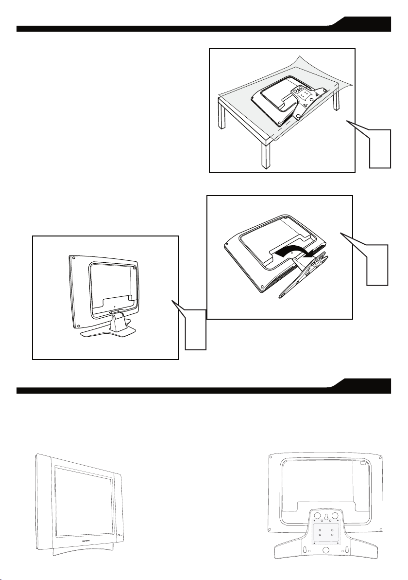
BEFORE INSTALLATION
B
efore p roceed to install your new LCD TV, please
follow the ste ps an d diagrams as show n to
familiarize yourself with the correct and safe way of
unfolding th e base.
Place the set facing down on a fl at surface and a
protective sheet.
Unfold the base following the direction as shown on
the diagram.
Place the set upright, you LCD TV is now ready for
install.
I
NSTALLING LCD TV ON THE WALL
The stand of your LCD TV is comply with Standard VESA 75 standard, if you intend to install the LCD TV on the wall,
please consult a professional technician for proper installing.
The manufacture accepts no liability for installations not performed by professional technician.
1
2
3
75x75mm
1
2
3
Page 6
CC
SOURC E
PI P
ME N U
OK
- + - +
B
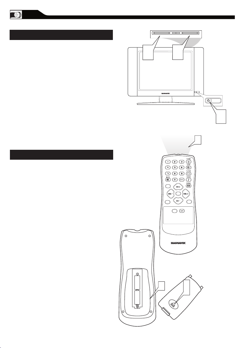
ASIC TV AND REMOTE CONTROL OPERATIONS
TELEVISION AND REMOTE CONTROL
Plug the DC adapter into the DC IN 16V jack
1
on the LCD T V. Plug the power cable into an
outlet.
Press POWER to turn on the LCD TV.
2
Press VOLUME + to increase the sound level.
Or, press VOLUME – to lower the sound level.
3
Press CH+ or CH- to select channels.
4
Point the remote control toward on the front
of the
5
6
7
8
LCD TV when
operating the LCD TV with the
remote.
BATTERY INSTALLATION
Remove the battery compartment lid on the
back of the remote.
Place two AAA batteries in the
remote. Be sure the (+) and (-) ends of the
batteries line up as marked inside the battery
compartment.
Reattach the battery compartment lid.
6
Page 7
C C
SOU RC E
P I P
M E N U
OK
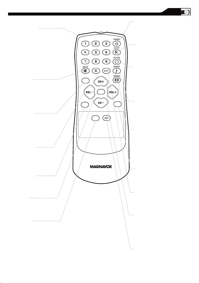
Number buttons
Press to select TV channels.
When selecting single-digit
channels, press the number of the
desired channel.
The LCD TV will pause for a few
seconds then tune to the selected
channel.
Mute button
Press to eliminate or restore the
LCD TV sound. Mute will appear
on the screen when the sound is
muted.
Menu butto
n
Press to activate onscreen menu,
back to previous level inside the
onscreen menu, also press to exit
the onscreen menu.
Volume button
Press to increase or decrease the
sound level, also press to navigate
left/right in onscreen menu.
Source button
Press to select the video input
source: AV, S-Video, HD, PC, T V.
OK button
Press to confirm the option you
selected in the onscreen menu.
C.C button
Press the C.C button to select CC
on or CC off.
REMOTE CONTROL
Standby (Power) button
Press to turn the LCD TV on or
off.
Sleep button
Press to set the LCD TV to turn
itself off within a certain time.
Smart Picture button
Press repeatedly to select either
Personal, Movie, Sports, Weak
signal, or Multimedia picture
setting.
Smart Sound button
Press repeatedly to select among
the 4 settings; Personal, News,
Music, or Theater.
Picture Format button
Press the FORMAT button
repeatedly to toggle among the
four screen format sizes; 4 :3,
EXPAND 4:3, COMPRESS 16:9
,
or HD 4:3.
PIP button
Press repeatedly to change the
size of PIP window in PC mode.
Previous Channel button
Press to go to previously selected
channel.
Channel but ton
Press to adjust the channel up
or down. Also press to select or
navigate up/down in onscreen
menu.
SAP button
Press to select a sound mode if
available with the T V
programming:Mono, Stereo, or
SAP.
7
Page 8
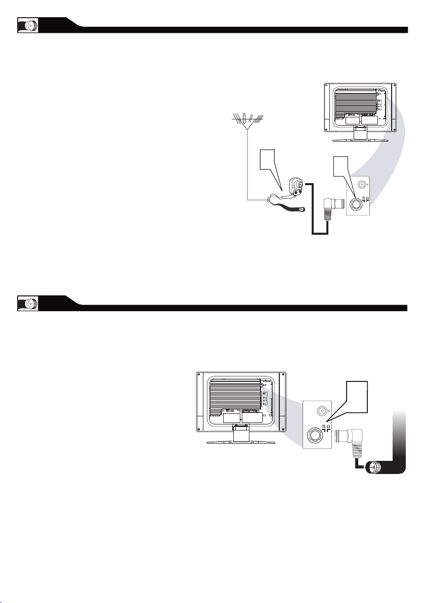
ANTENNA CONNECTION
Antenna
with 75
�
cable
Rear Jack panel of
Television
Outdoor or Indoor Antenna
(Combination VHF/UHF)
OR
Twin-lead
wire to
300-75
�
adapter
�
The Cable TV signal from
Cable Company
(75 coaxial cable)
Rear Jack panel of
Television
�
combination antenna receives normal
A
broadcast channels (VHF 2–13 and UHF 14–69).
Your connection is easy because there is only one 75
Ω(ohm) antenna jack on the back of your TV, and that’s
where the antenna goes.
If your antenna has a round cable
1
(75 ohm) on the end, then you’re ready to
connect it to the LCD TV. If your
antenna has flat, twin-lead wire (300 ohm), you
first need to attach the
antenna wires to the screws on a 300- to
75-ohm adapter(not supplied).
Connect the antenna (or adapter) to one end
of the supplied L-Adapter as shown, and con
2
nect the other end of the
L-Adapter to the TV jack on the side of
the LCD TV.
-
BASIC CABLE TV CONNECTION
L-Adapter
our Cable TV signal into your home may be a
Y
single, 75Ω(ohm) cable. If so, this connection is
very simple. Follow the step below to connect your
Cable TV signal to your new LCD TV.
Connect the Cable TV signal to one end of the
1
supplied L-Adapter as shown, and connect the
other end of the adapter to the TV jack on the
LCD TV.
L-Adapter
8
Page 9

TO TV
CABLE
IN
OUTPUT
CH
3 4
The Cable TV signal from
the Cable Compan
y
75
Coaxial
Cable
Side Jack Panel of
Television
�
DC Adapter
Power
Cable
VGA
PC
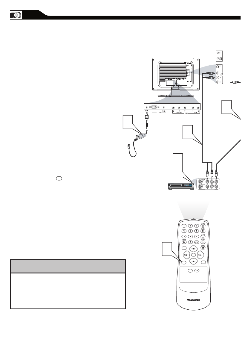
CABLE BOX CONNECTIONS
S - VIDEO
CABLE
IN
TO
TV
VIDEO
OUT
L
R
AUDIO
OUT
3 4
OUTPUT
CH
VIDEO
Cable
TV signal
Video Cable
Cable Bo
x
Audio Cable
Side Jack Panel
of
Television
AUDIO
DC Adapter
Power
Cable
VGA
PC
f you have a Cable Box, follow either set
I
of these steps to complete your
connections.
Cable Box with RF In/Out Jacks
This connection will not supply Stereo sound
to the LCD TV.
Connect the Cable T V signal to the IN jack (or
RF IN or CABLE IN) on the Cable Box.
1
Connect an RF coaxial cable (not supplied) to
the OUT jack (or TO TV or RF OUT) of the
2
Cable Box.
Connect the other end of the coaxial cable to
3
one end of the supplied L-Adapter as shown,
and connect the other end of the adapter to
the TV jack on the LCD TV.
Plug the DC adapter into the DC IN 16V
jack on the LCD TV. Plug the power cable into
4
an outlet.
Set the Channel 3/4 (or Output channel) switch
of the Cable Box to 3 or 4. Set the TV to the
5
same channel. When watching TV
programming, change channels at the Cable
Box, not the LCD TV.
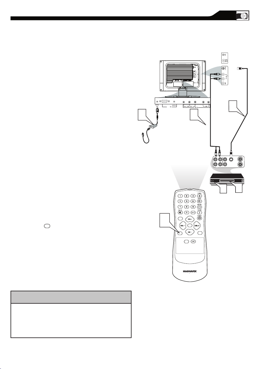
Cable Box with Audio/Video Out Jacks
This connection will supply Stereo sound to
the LCD TV.
Connect the Cable T V signal to the
IN jack (or RF IN or CABLE IN) on the Cable
1
Box.
L-Adapter
Using an RCA-type video cable (not
supplied) connect one end of the video cable to
2
the Video Out jack of the Cable Box.Connect
the other end of the cable to the yellow VIDEO
jack on the side of the TV.Video cables are
usually marked with yellow and are available
from Magnavox or electronics retailers. Video
jacks on most equipment are yellow.
Using RCA-type, stereo audio cables (not
supplied),
3
left and right Audio Out jacks of the Cable Box.
Connect the other end of that cable to the
Audio jack on the side of the LCD TV.Audio
cables are usually marked with red and white
and are available from Magnavox or electronics
retailers.The right
audio jack is red and the left audio jack is white.
Match the cable colors to the jack colors.
Plug the DC adapter into the DC IN 16V
4
jack on the LCD TV. Plug the power cable into
an outlet.
connect one end of the cables to the
9
Page 10
AUDIO/VIDEO INPUT CONNECTIONS
CC
SOURC E
PI P
ME NU
OK
VIDEO
S - VIDEO
AUDIO
VGA
PC
SOUR CE
he AUDIO and V IDEO In jack s on the
T
rear of th e LCD T V e na ble quick
connection s of other e quipment. Connect a VCR,
DVD Player, Video Ga me , Camcorder, etc., to
these jacks. To view the m aterial playing on the
other equipment, se t the LCD TV to its AV Mode.
Connect a RCA-style video cable
1
(usually yellow or marked CVBS) to the
VIDEO OUT jacks of the other
equipment (DVD Player, Camcorder, etc.) and
to the yellow VIDEO jack on the side of the
LCD TV.
Connect RCA-style audio cables (usually red
and white) to the AUDIO OUT (left and right)
2
jacks on the other equipment. Connect the
other end of the cables to the AUDIO jack on
the side of the LCD TV.
3
4
5
Plug the DC Adapter into the DC IN 16V jack
on the TV. Plug the power cable into an outlet.
Turn on the TV and other equipment.
Press the Source button to set the TV to
AV Mode.
Press PLAY on the other equipment to
view its material on the TV.
HELPFUL HINT
The Audio jack of AV IN is shared
between Video (CVBS) and S-Video signals. If Audio
and Video is connected to Video (CVBS) input, you
can still hear sound if you select S-Video via Source
select, even there appears no image on screen.
10
Page 11
S-VIDEO CONNECTIONS
CC
SOURC E
PI P
ME NU
OK
VIDEO
S - VIDEO
AUDIO
VGA
PC
SOUR CE
he S-Vid eo connection on the rea r of the
T
LCD T V can provi de you with bette r
picture d etail an d clarit y for the playback of
acc essory sources such as DBS (digital broadcast
satellite), DVD (digita l video discs), video games, and
VHS VCR (video ca ssette recorder) tapes tha n the
nor ma l a ntenna picture con ne ctions.
Note: The accessory device must have an S-VIDEO OUT
(put) jack in order for you to complete the connection
on this page.
Connect an S-Video cable to the S-VIDEO jack of
1
the other equipment (DVD Player, Camcorder, etc.)
and to the S-VIDEO jack on the rear of the LCD TV.
Connect RCA-style audio cables (usually red and
2
white) to the AUDIO OUT (left and right) jacks on
the other equipment. Connect the other end of the
cables to the AUDIO jack on the side of the LCD
TV.
Plug the DC Adapter into the DC IN 16V
3
jack on the LCD TV. Plug the power cable into an
outlet. Turn on the LCD TV and other
equipment .
Press the Source button to set
4
the LCD TV to its S-VIDEO mode.
Press PLAY on the other equipment to
5
view its material on the LCD TV.
The Audio jack of AV IN is shared between Video
(CVBS) and S-Video signals. If Audio and Video is
connected to S-Video input, you can still hear sound if
you select Video via Source select, even there appears
HELPFUL HINT
no image on screen.
11
Page 12
CC
SOURC E
PI P
ME NU
OK
ACCESSORY DEVICE
EQUIPPED WITH COMPONENT
VIDEO OUTPUTS.
VGA
PC
SOUR CE
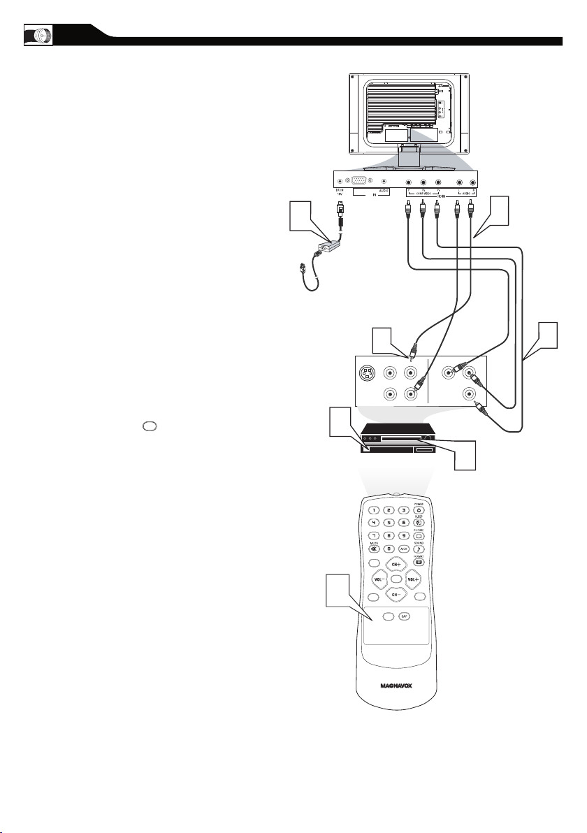
COMPONENT (YPBPR) CONNECTIONS
omponent Video input provid e the
C
high est possible color and picture
resolution in the pla yback of digital sig nal source
material, s uch as with DVD players.
Note: The accessory device must have an
component(YPbPr) output jack in order for you
to complete the connection on this page.
Connect the component (Y, Pb, Pr) Video OUT
jacks from the DVD player(or similar device) to
1
the COMP(onent) VIDEO Input jacks on the
bottom of the LCD TV.
Connect the red and white AUDIO CABLES to
the Audio (left ad right) output jacks on the rear
2
of the accessory device to the AUDIO IN jack.
Connect the other end of the cable to the Audio
jack on the rear of LCD TV.
Plug the DC Adapter into the DC IN 16 V jack
on the LCD TV. Plug the power cable into an
3
outlet. Turn on the LCD TV and other
equipment.
Press the SOURCE button on the remote
4
control to select HD. HD will appear in the
upper left corner on the TV screen.
Insert a DVD disc into the DVD player and press
the PLAY button on the
5
DVD Player.
12
Page 13

his LCD TV can be used as a PC .
CC
SOURC E
PI P
ME N U
OK
Side Jack Panel
of Television
VGA
PC
SOUR CE
T
Your computer will have to b e e quipp ed with a
VGA type vi de o output and VGA cable.
Connect one end of the VGA Video
cable (not supplied) to the Monitor (video)
1
output on the computer, while connecting the
other ends to the VGA INPUT jack on the LCD
TV.
Although audio connections are not required,
the LCD TV can reproduce the computers
2
audio out by an AUDIO ADAPTER to the Audio
output jack on the computer (if available) while
connecting the other ends of the Audio cables to
the PC AUDIO Jacks on the bottom of the TV.
Plug the DC Adapter into the DC IN 16V jack on
the LCD TV. Plug the power cable into an outlet.
3
Turn on the LCD TV and PC.
Press the SOURCE button until PC MODE
appears on the screen.
4
PC (MONITOR) CONNECTION
13
Page 14

LANGUAGE SETTINGS
MA IN C ON T RO LS
P IC TU RE
AU DI O
FE AT UR ES
IN ST AL L
LA NG UA GE
TU NE R MO D E
AU TO P RO G RA M
CH AN NE L E DI T
FA CT OR Y R ES ET
MA NU AL F I NE T UN E
CC
SOUR CE
PI P
ME N U
IN ST AL L
LA NG UA GE
TU NE R MO D E
AU TO P RO G RA M
CH AN NE L E DI T
FA CT OR Y R ES ET
EN GL IS H
MA NU AL F I NE T UN E
ME N U
ME N U
or English , French or Sp anish-speaking
F
TV own ers, an onscreen LANGUAGE option
is p resent. The LANGUAGEM cont rol en ables
you to set the TV’s onscre en menu to be shown in
either English, French or Spa ni sh.
Press the MENU button on the
1
remote control to see the onscreen menu.
Press the (CH-) button to highlight the
INSTALL menu.
2
Press the (VOL+) button to enter the
INSTALL menu.
3
Press the (VOL+) button to select English,
French or Spanish.
4
Press the MENU button repeatedly to clear
the menu from the screen.
5
Remember, the LANGUAGE control makes
only the TV’s onscreen MENU items
appear in English, French or Spanish text. It does
not change the other onscreen text features,
such as Closed Captioning (CC), with TV
shows.
HELPFUL HINT
14
Page 15

TUNER MODE CONTROL
MA IN C ON T RO LS
P IC TU RE
AU DI O
FE AT UR ES
IN ST AL L
LA NG UA GE
TU NE R MO D E
AU TO P RO G RA M
CH AN NE L E DI T
FA CT OR Y R ES ET
MA NU AL F I NE T UN E
CC
SOUR CE
PI P
ME N U
OK
IN ST AL L
LA NG UA GE
TU NE R MO D E
AU TO P RO G RA M
CH AN NE L E DI T
FA CT OR Y R ES ET
CA BL E
MA NU AL F I NE T UN E
ME N U
ME N U
he Tu n er Mode al l ows you to cha n ge the
T
LC D T V ’s sign al i npu t to Cab le o r A ir
(a nte n na) . It ’s i mpo rtan t fo r t h e L CD T V t o kn ow
if yo u wa nt t o r e cei ve c hann els fro m a cab l e T V
si gna l or an ant e nna sig nal.
Press the Menu button to see the onscreen
menu.
1
Press the (CH-) button to highlight the
INSTALL menu.
2
Press the (VOL+) button to enter the
INSTALL menu.
3
Press the (CH-) button to highlight the
TUNER MODE menu.
4
Press the (VOL+) or (VOL-)
buttons to select CABLE, AIR (antenna), or
5
AUTO.
Press the MENU button repeatedly to clear
the menu from the screen.
6
HELPFUL HINT
•When CABLE is selected, channels 1-125 are
available.
•When ANTENNA is selected, channels 2-69
are available.
•When AUTO is selected, your LCD TV will
search automatically for antenna and cable
channels.
15
Page 16

AUTO PROGRAM (SETTING UP CHANNELS)
AU TO ST OR E
PL EA S E WA IT
PR OG . FO UN D 0
CH AN N EL 3
CC
SOUR CE
P I P
ME N U
O K
IN ST A LL
LA NG U AG E
TU NE R M OD E
AU TO PR OG RA M
CH AN N EL E DI T
FA CT O RY R ES ET
EN GL I SH
IN ST A LL
LA NG U AG E
TU NE R M OD E
AU TO PR OG RA M
CH AN N EL E DI T
FA CT O RY R ES ET
ST AR T ?
MA NU A L FI NE T UN E
MA NU A L FI NE T UN E
ME N U
ME N U
our LCD TV ca n a utoma tically set itself for loca l
Y
are a (or c able T V) channels. This makes it ea sy
for you to select only the TV station s in your area by
pre ssing the CH (+) or CH (-) button.
Press the MENU button on the remote
control to show the
1
onscreen menu.
Press the (CH-) button to
highlight the INSTALL menu.
2
Press the (VOL+) button
to enter the INSTALL menu.
3
Press the (CH-) button to
highlight the AUTO PROGRAM control.
4
Press the (VOL+) button to start the AUTO
PROGRAM scanning of channels.
5
Press the MENU button repeatedly to clear
the menu from the screen, after AUTO STORE
6
has finished.
After you’ve run Auto Program, check out
the results. Press the CH+ or the
CH- button and see which channels you can
select.
Remember, an antenna or cable TV signal
must first be connected to your LCD TV
(see pages 8-9 of this owner’s manual).
HELPFUL HINT
16
Page 17

MA IN C ON T RO LS
P IC TU RE
AU DI O
FE AT UR ES
IN ST AL L
LA NG UA GE
TU NE R MO D E
AU TO P RO G RA M
CH AN NE L E DI T
FA CT OR Y R ES ET
MA NU AL F I NE T UN E
CC
SOUR CE
P I P
ME N U
OK
CH AN NE L E DI T
CH AN NE L
SK IP PE D
AC TI VE
CH AN NE L E DI T
CH AN NE L
SK IP PE D
2
IN ST AL L
LA NG UA GE
TU NE R MO DE
AU TO P RO GR A M
CH AN NE L ED I T
CH AN NE L
FA CT OR Y RE S ET
SK IP PE D
MA NU AL F IN E T UN E
hannel Edit cont rol lets you edit the chan nel
ME N U
ME N U
C
listing. You can add or remove a channel in
the LCD TV’s memory.
Press the Menu button to see the
1
onscreen menu.
Press the (CH -) but ton to
2
highlight the INSTALL menu.
Press the ( VOL+) but ton to enter the
3
INSTALL menu.
Press the (CH -) but ton to
4
highlight the CHANNEL EDIT menu.
Press the ( VOL+) but ton to enter the
5
CHANNEL EDIT menu.
In CHANNEL column, press (VOL+) or
6
(VO L-) to select the channel you wish
to add or remove .
CHANNEL EDIT CONTROL
In S KIPPED column , press (VOL+) or
7
(VOL-) to select ACTIVE (to add)
or S KIPPED (to delete) the channel you
selected.
Press the MEN U button
8
repeatedly to clear the menu from the
screen.
Repeat steps 6 –7 to add or delete
additional channels to or from the
LCD TV’s memory.
HELPFUL HINT
17
Page 18

our TV ca n be reset to the original
MA IN C O NT RO LS
P IC TU R E
AU DI O
FE AT UR E S
IN ST AL L
LA NG UA G E
TU NE R M OD E
AU TO P R OG RA M
CH AN NE L E DI T
FA CT OR Y R ES ET
CC
SOUR CE
P I P
ME N U
O K
IN ST AL L
LA NG UA G E
TU NE R M OD E
AU TO P R OG RA M
CH AN NE L E DI T
FA CT OR Y R ES ET
YE S
MA NU AL FI NE T UN E
MA NU AL FI NE T UN E
ME N U
ME N U
Y
factory settings by perfor ming the
following steps.
Press the MENU button on the
remote control to see the onscreen
1
menu.
Press the (CH-) button to highlight the
INSTALL menu.
2
Press the (VOL+) button to enter the
INSTALL menu.
3
Press the (CH-) button to highlight the
FACTORY RESET control.
4
Press the (VOL+) button to reset the TV
to the original factory settings.
5
Press the MENU button repeatedly to
clear the menu from the screen.
6
ACTORY RESET
F
HELPFUL HINT
If you reset the TV to the factory settings,
all your present setting on picture, audio,
Close Caption and other feature settings
will be erased and replaced by the
manufacture’s default settings. However,
your AutoLock access code will not be
erased. Please refer to page 23 for details.
18
Page 19

S
CC
SOURCE
PI P
MEN U
OK
Personal
Movies
Sports
Weak Signal
Multimedia
Night
CC
SOURCE
PI P
MEN U
OK
Personal
News
Music
Theatre
MART PICTURE CONTROL
hether you’re watching a movie or a video
game, your LCD TV has video control preset
W
that will match with your current program source
or content. Smart Picture quickly resets your TV’s
video controls for a number of different types of
programs and viewing conditions that you may
have in your home. The Movies, Sports, Weak
Signal, Multimedia, and Night Smart Picture
controls have been preset at the factory to easily
adjust the TV’s bright ness, color, picture,
sharpness, tint, and color temperature levels. In
the Personal smart picture mode you can create
your own preferred video settings.
Press the PICTURE button on the remote
control. The current Smart Picture setting will appear
1
on the screen.
Press the PICTURE button repeatedly to
2
select either Personal, Movies, Sports, Weak
Signal, Multimedia, and Night Smart Picture settings.
Note: The set tings of the Personal smart picture mode
can be adjusted in pic ture options within the onscreen
menu. The Personal mode is the only mode which
can be adjusted by t he user via the onscreen picture
control menu.
MART SOUND CONTROL
S
mart Sound allows you to select from
S
three user presets and a personal mode
that you set according to you own
preferences through the onscreen Sound
menu. The three user presets(News, Music,
and Theatre) enable you to tailor the TV
sound so as to enhance the particular
program you are watching. Following these
steps to select any of the options.
Press the Sound button on the remote control. The
current Smart Sound setting will appears on the
1
screen.
Press the Sound button repeatedly to toggle among
2
the four setting: Personal, News, Music, or Theatre.
Note: The settings of the Personal smart sound mode can
be adjusted in sound control within the onscreen
menu. The Personal mode is the only mode which
can be adjusted by the user via the onscreen sound
control menu.
19
Page 20

o adjust you r LCD T V picture, select
CC
SOUR CE
P I P
ME N U
O K
MA IN C O NT RO LS
PI CT U RE
AU DI O
FE AT UR E S
IN ST AL L
SM AR T P IC TU RE
BR IG HT N ES S
CO LO R
CO NT RA S T
TI NT
SH AR PN E SS
PI CT UR E
SM AR T P IC TU RE
BR IG HT N ES S
CO LO R
CO NT RA S T
SH AR PN E SS
TI NT
PE RS ON A L
PI CT UR E
SM AR T P IC TU RE
BR IG HT N ES S
CO LO R
CO NT RA S T
SH AR PN E SS
TI NT
60
PI CT UR E
SM AR T P IC TU RE
BR IG HT N ES S
CO LO R
CO NT RA S T
SH AR PN E SS
TI NT
60
PI CT UR E
SM AR T P IC TU RE
BR IG HT N ES S
CO LO R
CO NT RA S T
SH AR PN E SS
TI NT
60
PI CT UR E
SM AR T P IC TU RE
BR IG HT N ES S
CO LO R
CO NT RA S T
SH AR PN E SS
TI NT
60
PI CT UR E
SM AR T P IC TU RE
BR IG HT N ES S
CO LO R
CO NT RA S T
SH AR PN E SS
TI NT
60
ME N U
ME N U
T
a chan nel and follow these steps.
Press the MENU button to see the
1
onscreen menu.
When PICTURE menu is
2
highlighted,press the (VOL+) button
to enter the
PICTURE menu.
Press the (CH +) or (CH-)
3
button to choose the item you want to
adjust: Smart Picture, Brightness, Color,
Contrast ,
Sharpness or Tint.
Smart Picture
page 20, for details on Smart Picture
Settings.
Brightness: Adjust to brighten the
dark parts of the picture. This
appears to add white to the color.
Press the (VOL+) or (VOL-)
4
button to adjust the item.
Press the (CH +) or (CH-)
5
button to select and adjust other picture
controls.
Press the MENU button repeatedly
6
to remove the menu.
Color: Adjust to add or reduce
color.
Contrast : Adjust to “sharpen” the
Picture quality. The black portions of
the picture become richer in darkness
and the white become brighter.
Sharpness: Adjust to improve detail.
Tint: Adjust to obtain natural skin
tones.
Brightness, color, contrast and
sharpness can only be accessed when
Smart Picture is set to PERSONAL.
HELPFUL HINT
: Please refer to
TV P
ICTURE MENU CONTROLS
20
Page 21

o adjust you r LCD T V S ou nd , sele ct a channel
CC
SOUR CE
P I P
ME N U
O K
MA IN C ON T RO LS
PI CT UR E
AU DI O
FE AT UR ES
IN ST AL L
SM AR T SO U ND
SE TT IN GS
ST ER EO
VIR TUA L S URR OUN D
AV L
AU DI O
SM AR T SO U ND
SE TT IN GS
ST ER EO
VIR TUA L S URR OUN D
AV L
PE RS ON AL
AU DI O
SM AR T SO U ND
SE TT IN GS
ST ER EO
VIR TUA L S URR OUN D
AV L
TR EB LE
BA SS
BA LA NC E
AU DI O
SM AR T SO U ND
SE TT IN GS
ST ER EO
ST ER EO
VIR TUA L S URR OUN D
AV L
AU DI O
SM AR T SO U ND
SE TT IN GS
ST ER EO
VIR TUA L S URR OUN D VIR TUA L S URR OUN D
AV L
AU DI O
SM AR T SO U ND
SE TT IN GS
ST ER EO
VIR TUA L S URR OUN D
YES
AV L
ME N U
ME N U
T
and follow these steps.
Press the MENU button to see the menu.
1
Press the (CH-) button to highlight the
2
AUDIO menu.
Press the (VOL+) button to enter the
3
AUDIO menu.
Press the (CH +) or (CH-) button to
4
choose the item you want to adjust: Smar t
Sound, Settings, Stereo, Virtual Surround,
AVL.
Smart Sound: Please refer to page19 for
details on Smart Sound Settings.
Settings: Allows you to adjust Treble, Bass,
and Balance of the sound.
Stereo: Adjust to select between Stereo,
Mono, or SAP.
Virtual Surround: Adds greater depth and
dimension to TV sound. Select from Virtual
Surround or OFF.
AVL (Auto Volume Leveler): When On, AVL
will level out the sound being heard when
sudden changes in volume occur during
commercial breaks or channel changes.
Press the (VOL+) or (VOL-) button to
5
adjust the item.
Press the (CH +) or (CH-) button to
6
select and adjust other sound controls.
Press MENU to remove the menu.
7
•Treble and Bass can only be accessed
when Smart Sound is set to Personal.
•If Stereo is not presented on a
selected show and the TV is placed in
Stereo mode, the sound coming from
TV will remain in Mono mode.
HELPFUL HINT
TV SOUND MENU CONTROLS
21
Page 22

MOVIE R A T I N G
G
PG
PG13
R
NC17
X
ON
TV R A T I N G
Y
Y7
G
PG
14
MA
ON
he AU TO Lock feature is a n
T
integrated circuit tha t receives
and processes da ta sent by
broadcaste rs, or other program
provid ers, tha t contain prog ra m
content advisories.When programmed
by the vie we r, a TV with AUTO Lock
can respond to the content
advisories and block program conte nt
that may be found objectionable (such
as offensive language, violence, sexual
situations, etc.). This is a great feature
to censor the t ype of viewin g children
may wa tch.
AUTO Lock offers various BLOCKING
controls from which to choose:
Access Code - An Access Code must be
set to prevent children from unblocking
questionable or censored programming set
by their parents.
Block E nable - After an access code has
been programmed , you can block
programming depending on the received
rating and user set ting.
Movie Rating s - Cer tain blocking options
exist which will block programming b ased
on ratings patterned by the Motion Pictures
Association of Americ a.
TV Ratings - Just like the Movie Rating s,
programs can be blocked from viewing using
standard T V ratings set by TV broadcasters.
AUTO LOCK
MOVIE RATINGS
G: General Audience - All ages
admit ted.
Most parents would find this progr am
suitable for all ages. This type of
programming cont ains little or no
violence, no strong language, and little
or no sexual dialog or situations.
PG: Parental Guidance Suggested This programming contains material
that parent s may find unsuitable for
younger children. It may contain one
or more of t he following:
moder ate violence, some sexual
situations, infrequent coarse
language, or some suggestive dialog.
PG-13: Parents Strongly
Cautioned
This programming contains
material that parents may find
unsuitable for children under the age
of 13. It contains one or more of the
following: violence, sexual situations,
coarse language, or sug gestive dialog.
R: Restricted -This programming
is specifically designed for adults.
Anyone under the age of 17 should
only view this programming with an
accompanying
parent or adult guardian. It contains
one or more of the following: intense
violence, intense sexual situations,
strong coarse language , or intensely
suggestive dialog.
NC-17: No children under the age
of 17 will be admitted. - This type
of progr amming should be viewed by
adults only. It contains graphic
violence, explicit sex, or crude,
indecent language.
X: Adults Only
programming contains one or more of
the following: ver y graphic violence,
very graphic and explicit or indecent
sexual acts, and very coarse and
intensely suggestive language
-
- This type of
22
TV RATINGS
TV-Y All children - Appropri ate for
all children. Designed for a very young
audience, including children ages 2-6.
This type of programming is not
expected to frighten younger children.
TV-Y7 Directed to Older Children Designed for children age 7 and above .
It may be more appropriate for
children who can distinguish between
make-believe and reality. This
programming may include mild fantasy
and comic violence (FV or f antasy
violence).
TV-G General Audience - Most
parents would find this programming
suitable for all ages. This type of
programming cont ains little or no
violence, no strong language, and little
or no sexual dialog or situations.
TV- PG Pa rental Guidanc e
Sug ge sted
Contains material that pare nts may
find unsuitable for younger children.
This type of programming contains one
or more of t he following: Moderate
violence (V), some sexual situations
(S) , infrequent coarse language (L), or
some suggestive dialog (D) .
TV-14 Parents Strongly Cautioned Contains some material that many
parents would find unsuitable for
children under age 14. This type of
programming cont ains one or more of
the following: intense violence (V),
intense sexual situations ( S), strong
coarse language ( L), or intensely
suggestive dialog (D ).
TV-MA Mature Audience Only
Specifically designed to be viewed
by adult s and may be unsuitable
for children under 17. This type of
programming cont ains one or more
of the following: graphic violence ( V),
explicit sexual situations (S), or crude,
indecent language (L)
-
-
Page 23

ver the next fe w pages you’ll learn how
MA IN C ON T RO LS
P IC TU RE
AU DI O
FE AT UR ES
IN ST AL L
SO UR CE
PI CT UR E F OR MA T
AU TO LO CK
CL OS ED C A PT IO N
PI CT UR E A LI GN ME NT
CC
SOUR CE
P I P
ME N U
O K
CH AN GE C O DE
EN TE R NE W C OD E - -- -
CO NF IR M C OD E - -- -
FE AT UR ES
LO CK P RO G RA M
CH AN G CO D E
CL EA R AL L
BL OC K OP T IO N
MO VI E RA T IN G
TV R AT IN G
PI CT UR E A LI GN ME NT
SO UR CE
PI CT UR E F OR MA T
AU TO LO CK
CL OS ED C A PT IO N
ME N U
ME N U
O
to bloc k prog ra ms and understand th e rating
ter ms for certain broa dcasts. First, set an acces s
cod e.
Press the MENU button to see the
1
onscreen menu.
Press the (CH-) button to highlight the
FEATURES menu.
2
Press the (VOL+) button to enter the
FEATURES menu.
3
Press the (CH-) button to select AUTO
LOCK.
4
Press the (VOL+) button
CHANGE CODE will appear on the screen.
5
Enter a four-digit code using the Number
buttons. The screen will prompt you to confirm
6
the code you just entered. Enter your same new
code again.
Press MENU repeatedly to remove
the menu from the screen.
7
HELPFUL HINT
Remember that 0711 is the default AutoLock
code. If your access code has been changed by
someone other than you (a child, for example)
or you have forgotten the code, you can always
get in by inputting the default code.
AUTO LOCK ACCESS CODE
NOTE TO PARENTS:
It is not possible for your child to unblock a channel
without knowing your access code or changing it to a
new one. If your code has been changed without your
knowledge, then you will become aware that blocked
channels may have been viewed.
23
Page 24

fte r your personal access c ode has been
CC
SOUR CE
P I P
ME N U
O K
MA IN C ON T RO LS
P IC TU RE
AU DI O
FE AT UR ES
IN ST AL L
SO UR CE
PI CT UR E F OR MA T
AU TO LO CK
CL OS ED C A PT IO N
PI CT UR E A LI GN ME NT
AU TO LO CK
LO CK P RO G RA M
CH AN GE C O DE
CL EA R AL L
BL OC K OP T IO N
MO VI E RA T IN G
TV R AT IN G
18
AU TO L OC K
AC CE S S CO DE -- --
FE AT UR ES
LO CK P RO G RA M
CH AN G CO D E
CL EA R AL L
BL OC K OP T IO N
MO VI E RA T IN G
TV R AT IN G
SO UR CE
PI CT UR E F OR MA T
AU TO LO CK
CL OS ED C A PT IO N
PI CT UR E A LI GN ME NT
ME N U
ME N U
A
set (see the previou s page), you are ready to
select the channels or inputs you want to bloc k out
or cen sor.
Press the MENU button to see the
onscreen menu.
1
Press the (CH-) button to highlight the
FEATURES menu.
2
Press the (VOL+) button to enter the
FEATURES menu.
3
Press the (CH-) button to select
AUTO LOCK.
4
Press the (VOL+) button to enter
5
AUTO LOCK menu.
Use the Number buttons to enter
your access code.
6
Press the (VOL+) button to block
current selected channel or (VOL-)
7
button to unblock a channel.
Press MENU repeatedly to remove the
8
menu from the screen.
AUTO LOCK PROGRAM
Note:You can block additional channels by using
Number buttons to jump to another channel.
24
Page 25

AUTO LOCK - MOVIE RATINGS
CC
SOUR CE
P I P
ME N U
OK
MA IN C ON T RO LS
P IC TU RE
AU DI O
FE AT UR ES
IN ST AL L
SO UR CE
PI CT UR E F OR MA T
AU TO LO CK
CL OS ED C A PT IO N
PI CT UR E A LI GN ME NT
AU TO LO CK
LO CK P RO G RA M
CH AN GE C O DE
CL EA R AL L
BL OC K OP T IO N
MO VI E RA T IN G
TV R AT IN G
G
PG
PG 13
R
NC 17
X
MO VI E RA T IN G
G
PG
PG 13
R
NO
X
NC1 7
AU TO LO C K
AC CE SS CO DE -- --
FE AT UR ES
LO CK P RO G RA M
CH AN G CO D E
CL EA R AL L
BL OC K OP T IO N
MO VI E RA T IN G
TV R AT IN G
SO UR CE
PI CT UR E F OR MA T
AU TO LO CK
CL OS ED C A PT IO N
PI CT UR E A LI GN ME NT
ME N U
ME N U
he AU TO Lock feature can block programming
T
based on the Movie Indu stry ra tings.
Onc e you’ve entered you r a ccess code and the AUTO
Lock features are displayed on the
screen:
Press the MENU button to see the
onscreen menu.
1
Press the (CH-) button to highlight the
FEATURES menu.
2
Press the (VOL+) button to enter the
FEATURES menu.
3
Press the (CH-) button to select AUTO
LOCK.
4
Press the (VOL+) button, INPUT USER CODE
will appear.
5
Use the Number buttons to enter your access
code.
6
Press the (CH-) button to select MOVIE
RATING.
7
Press the (VOL+) button to highlight any of the
Movie Rating options. When highlighted, all
8
these options can be (ON) blocked or (OFF)
unblocked.
Press MENU repeatedly to remove the menu
from the screen.
9
HELPFUL HINT
When a rating is chosen to be blocked, any
higher level rating will also be blocked from
viewing. (i.e.: If “R” is selected to be blocked,
NC-17 and X will automatically be blocked.)
When a rating is set to unblock, only the selected
rating will be unblocked (Ratings lower will not
automatically be unblocked.)
25
Page 26

he AU TO Lock feature can block
MA IN C O NT RO LS
P IC TU R E
AU DI O
FE AT UR E S
IN ST AL L
SO UR CE
PI CT UR E F OR MA T
AU TO LO C K
CL OS ED CA PT IO N
PI CT UR E A LI GN ME NT
CC
SOUR CE
P I P
ME N U
O K
AU TO LO C K
LO CK P R OG RA M
CH AN GE CO DE
CL EA R A LL
BL OC K O PT IO N
MO VI E R AT IN G
TV R AT I NG
Y
Y7
G
PG
14
MA
TV R AT I NG
G
Y
Y7
PG
NO
MA
14
AU TO L OC K
AC CE S S CO DE -- --
FE AT UR E S
LO CK P R OG RA M
CH AN G C OD E
CL EA R A LL
BL OC K O PT IO N
MO VI E R AT IN G
TV R AT I NG
SO UR CE
PI CT UR E F OR MA T
AU TO LO C K
CL OS ED CA PT IO N
PI CT UR E A LI GN ME NT
ME N U
ME N U
T
programming based on the TV
Industr y ratings.O nce you’ve entered you r
acc ess code and the AUTO Lock feature s a re
displa ye d on the screen:
Press the MENU button to see the
onscreen menu.
1
Press the (CH-) button to
highlight the FEATURES menu.
2
Press the (VOL+) button
to enter the FEATURES menu.
3
Press the (CH-) button to
highlight AUTO Lock.
4
Press the (VOL+) button,
INPUT USER CODE will appear on the
5
screen.
Use the Number buttons to enter your
access code.
6
Press the (CH-) button to select TV
RATING.
7
Press the (VOL+) or (VOL-)
button to highlight any of the TV
8
Rating options. When highlighted, all these
options can be (ON) blocked or (OFF)
unblocked.
When a rating is chosen to be blocked, any
higher level rating will also be blocked from
viewing. (i.e.: If “R” is selected to be blocked,
NC-17 and X will automatically be blocked.)
When a rating is set to unblock, only the selected
rating will be unblocked (Ratings lower will not
automatically be unblocked.)
HELPFUL HINT
AUTO LOCK - TV RATINGS
Press MENU repeatedly to
9
remove the menu from the screen.
26
Page 27

ou can change the picture format size to match
MA IN C ON T RO LS
P IC TU RE
AU DI O
FE AT UR ES
IN ST AL L
SO UR CE
PI CT UR E F OR MA T
AU TO LO CK
CL OS ED C A PT IO N
PI CT UR E A LI GN ME NT
CC
SOUR CE
PI P
ME N U
OK
4:3
HD 4:3
EXPAND 4:3
COMPRESS16:9
FE AT UR ES
4 : 3
SO UR CE
PI CT UR E F OR MA T
AU TO LO CK
CL OS ED C A PT IO N
PI CT UR E A LI GN ME NT
ME N U
ME N U
Y
the type of program you are watching. Select
the normal 4:3, EXPAND 4:3, or COM PRESS 16:9,
or HD 4:3 aspect ratios.
Press the MENU button to see the
1
onscreen menu.
Press (CH -) button to highlight the
FEATURES menu.
2
Press (VOL+) button to enter the
FEATURES menu.
3
Press (CH -) button to highlight the
PICTURE FORMAT menu.
4
Press (VOL+) button to change the
5
PICTURE FORMAT.
Note: Press the FORMAT button repeatedly
to toggle among the four screen format
sizes; 4:3, EXPAND 4:3, or COMPRESS
16:9, or HD 4:3.
U
SING THE PICTURE FORMAT
Press MENU repeatedly to
remove the menu from the screen.
6
Note: HD 4:3 Picture Format is available in HD Mode
with 720p/1080i only.
27
Page 28

CLOSED CAPTIONS
CC
SOUR CE
P I P
ME N U
OK
MA IN C O NT RO LS
P IC TU R E
AU DI O
FE AT UR E S
IN ST AL L
SO UR CE
PI CT UR E F OR MA T
AU TO LO C K
CL OS ED CA PT IO N
PI CT UR E A LI GN ME NT
CL OS ED CA PT IO N
CA PT IO N M OD E
CC D IS P LA Y
CC 1
FE AT UR E S
CA PT IO N M OD E
CC D IS P LA Y
SO UR CE
PI CT UR E F OR MA T
AU TO LO C K
CL OS ED CA PT IO N
PI CT UR E A LI GN ME NT
ME N U
losed Captioning (CC) allows you to
C
read the voice con tent of tele vi sion
programs on the T V screen . Designed to help the
hea ring impaired, thi s feature u ses onscre en “text
boxes” to sh ow dialogue and conversations while th e
TV program is in progress.
Press the MENU button to see the onscreen
1
menu.
Press the (CH -) button to highlight the
FEATURES menu.
2
Press the (VOL+) button to enter the
FEATURES menu.
3
Press the (CH -) button to select CLOSE
CAPTION.
4
Press the (VOL+) button to select the closed
caption you want: CC MUTE, CC1, CC2, CC3,
5
CC4, Txt1, Txt2, Txt3 or Txt4.
Note:Closed Caption can also be activated by pressing
CC button on your remote control.
Not all TV programs and product
commercials are broadcast with Closed
Captioning (CC). Nor are all Closed
Captioning MODES (CAPTION 1–4 or TEXT 1–4)
necessarily being used by broadcast
stations during the transmission of a program
offering Closed Captioning. Refer to your area’s TV
program listings for the stations and times of shows
being broadcast with Closed Captioning.
HELPFUL HINT
28
Page 29

his TV can also be used as a PC Monitor. A
CC
SOUR CE
P I P
ME N U
O K
PI CT UR E
SM AR T PI C TU RE
BR IG HT NE S S
CO NT RA ST
AU TO A DJ U ST
MA NU AL A D JU ST
60
PI CT UR E
SM AR T PI C TU RE
BR IG HT NE S S
CO NT RA ST
60
AU TO A DJ U ST
MA NU AL A D JU ST
PI CT UR E
SM AR T PI C TU RE
BR IG HT NE S S
CO NT RA ST
AU TO A DJ U ST
MA NU AL A D JU ST
YE S
PI CT UR E
SM AR T PI C TU RE
BR IG HT NE S S
CO NT RA ST
AU TO A DJ U ST
MA NU AL A D JU ST
PH AS E
CL OC K
HO RI ZO NT A L
VE RT IC AL
MA IN C ON T RO LS
PI CT UR E
AU DI O
FE AT UR ES
IN ST AL L
SM AR T PI C TU RE
BR IG HT NE S S
CO NT RA ST
AU TO A DJ U ST
MA NU AL A D JU ST
PI CT UR E
SM AR T PI C TU RE
BR IG HT NE S S
CO NT RA ST
NO RM AL
AU TO A DJ U ST
MA NU AL A D JU ST
ME N U
ME N U
T
PC video signal must be prese nt or the TV will
go into standby mode . T he PC Picture
controls allow you to adjust the pictu re.
allow you to adjust th e pict ure.
Note: Make sure you are in PC mode.
Press the MENU button on the remote
1
control to see the onscreen menu.
When the PICTURE menu is highlighted, press
2
the (VOL+) button to enter the PICTURE
menu.
Press the (CH +) or (CH -) button to
highlight the item that you would like to adjust.
3
Smart Picture: Adjust the color
temperature of the picture. Select from
Normal, Cool, or Warm.
Brightness: Adjust to brighten the darkest
parts of the picture.
Contrast: Adjust to “sharpen” the Picture
quality. The black portions of the picture
become richer in darkness and the white
become brighter.
Auto Adjust: The LCD Monitor will
automatically adjust to the best image
position, phase, and clock setting.
Manual Adjust: The Manual Adjust control
allow you to manually fine tune the image as it
appears on the screen.
Phase-eliminates the horizontal
interfering lines.
Clock-eliminates the vertical interfering
lines.
Horizontal-adjust the horizontal
placement of the picture.
Vertical-adjust the vertical placement of the
picture.
Press the (VOL+) or (VOL-) button to
4
5
adjust the item.
Press MENU repeatedly to remove
the menu from the screen.
Note: To adjust other items repeat steps 4 and 5.
PC PICTURE CONTROLS
29
Page 30

his TV can also be used as a PC Monitor. A
MA IN C ON T RO LS
PI CT UR E
AU DI O
FE AT UR ES
IN ST AL L
SM AR T SO U ND
SE TT IN GS
ST ER EO
VI RT UA L S UR RO UN D
AV L
CC
SOUR CE
P I P
ME N U
O K
AU DI O
SM AR T SO U ND
SE TT IN GS
ST ER EO
VIR TUA L S URR OUN D
AV L
PE RS ON AL
AU DI O
SM AR T SO U ND
SE TT IN GS
ST ER EO
VIR TUA L S URR OUN D
AV L
TR EB LE
BA SS
BA LA NC E
AU DI O
SM AR T SO U ND
SE TT IN GS
ST ER EO
ST ER EO
VIR TUA L S URR OUN D
AV L
AU DI O
SM AR T SO U ND
SE TT IN GS
ST ER EO
VIR TUA L S URR OUN D VI RTU AL S URR OUN D
AV L
AU DI O
SM AR T SO U ND
SE TT IN GS
ST ER EO
VIR TUA L S URR OUN D
YES
AV L
ME N U
ME N U
T
PC video signal must be prese nt or the TV
will go into standb y mode. The AUDIO con trols
allow you to adjust th e sound.
Note: Make sure you are in PC mode.
Press the MENU button on the
remote control to show the
1
onscreen menu.
Press the (CH-) button to highlight the
AUDIO menu.
2
Press the (VOL+) button to shift the
menu to the right to enter the AUDIO
3
menu.
Press the (CH +) or (CH-)
button to highlight the item that you would
4
like to adjust:
Smart Sound: Allows you to select from 3
factory-set controls and a
personal control. The 3 factory-set
controls (News, Music, and Theatre)
enhance the particular program you are
watching.
Settings: Allows you to adjust Treble, Bass,
and Balance of the Sound.
Stereo: To select from Stereo, Mono, and
SAP.
Virtual Sound: Adds greater depth and
dimension to PC sound.
AVL (Auto Volume Leveler)- When ON,
AVL will level out the sound being heard
when sudden changes in volume occur
during commercial breaks or channel
changes.
Press the (VOL+) or (VOL-)
5
buttons to adjust the item.
Press MENU repeatedly to remove the
menu from the screen.
6
To adjust other items repeat steps 4 and 5.
HELPFUL HINT
PC AUDIO CONTROLS
30
Page 31

USING PC PIP (PICTURE IN PICTURE) FEATURE
MA IN C O NT RO LS
PI CT U RE
AU DI O
FE AT UR E S
IN ST AL L
PI P
SO UR CE
CC
SOUR CE
P I P
ME N U
FE AT UR E S
SO UR CE
PI P
SI ZE
VI DE O
AU DI O
DI SP LA Y
ME N U
IP ( Pictu re-in-Picture) feature allows you to
P
call up a subscree n when yo u a re using your
TV as a monitor.
Note: Make sure you are in PC mode.
Press the MENU button to see the
1
onscreen menu.
Press (CH -) button to highlight the
2
FEATURES menu.
Press (VOL+) button to enter the
FEATURES menu.
3
Press (VOL+) button to enter the PIP menu.
4
Press the (CH +) or ( CH -) buttons to
highlight the item that you would like to adjust.
5
SIZE: Turn off and set the size of PIP. You
can choose you preferred size of small,
medium, large, or PBP (Picture Beside
Picture).
Video: Select video source of PIP from AV,
S-Video, TV, or Component.
Audio: Select audio source of PIP or PC.
Display: Select which corner of the
position of PIP.
PIP windows with component video source can only
support up to 480i (SD) video signal.
HELPFUL HINT
31
Page 32

ETTING UP THE PC MODE (PERSONAL COMPUTER MONITOR)
S
15MF Series (15” LCD TV)
No Resolution Mode V. Frequency (Hz) H. Frequency (kHz)
1 640 x 480 VGA VESA 60 59.940 31.469
2
3 SVGA VESA 60 6 0. 317 37.897
4 1024 x 768 XGA VESA 60 60.004 48.363
20MF Series (20” LCD T V )
No Resolution Mode V. Frequency (Hz) H. Frequency (kHz)
1
2
3 SVGA VESA 60 60.317 37.897
80 0 x 600
640 x 480
800 x 600
SVGA VESA 56 56.250 35.156
VGA VESA 60 59.940 31.469
SVGA VESA 56 56.250 35.156
32
Page 33

TROUBLE SHOOTING TIPS
No Power
• Check the TV power cord. Disconnect the power cord from the power outlet for 10 seconds, then
reinsert the plug into the outlet. Press POWER to turn on the TV again.
• Make sure the outlet is not on a wall switch.
• Make sure a fuse has not blown at the power outlet.
No Picture
• Check the antenna or Cable TV connections. Connect the antenna or Cable TV signal securely to the
TV’s 75Ω jack on the rear of the TV.
• Set TUNER MODE correctly. Details are on page 15.
• Activate AUTO PROGRAM to find all available channels. Details are on page 16.
• In case you hear only sound and don’t see any picture in S-Video or Video (CVBS) mode. Please check if
you have connected Video signal to S-Video or Video (CVBS) input. Only one of the two video inputs can
be connected to sound. This means that the same sound can be heared in S-Video and Video (CVBS)
mode.
No Sound
• Press the VOL+ and VOL- buttons to adjust the volume.
• Press the MUTE button on the remote control to cancel or restore the volume.
• If you have connected other equipment to the TV (such as a VCR or DVD Player), make sure the audio
cables are connected securely between the TV and the other equipment.
• Check the SOUND settings. Details are on page 19 or 21.
• In case you hear wrong sound in S-Video or Video (CVBS) mode. Please check if you have connected the
right sound signal to AV in (S-Video or Video input). Only one of the two video inputs can be connected
to sound, but both video signals can be connected. This means that only one of the two sound inputs can
be heared in S-Video and Video (CVBS) mode.
Remote Control does not work.
• Check the batteries. If necessary, replace them with two AAA heavy duty (zinc chloride) or alkaline
batteries.
• Clean the remote control as well as the remote control sensor on the front of the TV.
• Check the TV power cord. Disconnect the power cord from the power outlet for 10 seconds, then rein
sert the plug into the outlet. Press POWER to turn on the TV again.
• Make sure the outlet is not on a wall switch.
• Make sure a fuse has not blown at the power outlet.
• Always point the remote control toward the front of the TV (toward the remote sensor).
• Make sure that you use the supplied Magnavox Remote control, only the supplied Magnavox Remote
control can be used with this LCD-TV set.
TV displays wrong channel or no channels.
• Repeat channel selection.
• Add the channel number(s) into the TV’s memory. Use STORE. Details are on page 15.
• Make sure TUNER MODE is set correctly. Details are on page 15.
Then activate AUTO PROGRAM to set up all available channels. Details are on page 16.
33
Page 34

CARE AND CLEANING
WARNING concerning stationary images on the TV
Screen: Do not leave fixed images on the screen for extended periods of time. This can cause uneven aging of the LCD
panel. Normal use of the TV should involve viewing of programs that have constantly moving or changing images. Do not
leave onmoving images on screen for extended periods of time. Do not display the same images too frequently; if you
do, subtle “ghost” images can be left on the LCD screen. Sources of stationary images may be Laser discs, video games,
Compact Discs Interactive (CD-i), or paused Digital Video Discs (DVDs) or video tapes.
Here are some common examples of stationary images:
• DVD menus list DVD content.
• Letterbox black bars appear at the top and bottom of the TV screen when a wide screen (16:9) movie is viewed on a
TV with standard (4:3) aspect ratio. This is available with some DVDs.
• Video game images and scoreboards
• Television station logos cause a problem if they are bright and stationary. Moving or low-contrast graphics are
less likely to damage the picture tube.
• Stock market tickers may appear at the bottom of the TV screen if the TV programming covers this news.
• Shopping channel logos, pricing displays may be bright and may appear constantly during the show.
These are usually in the same location on the TV screen.
TV Location
• To avoid cabinet warping, cabinet color changes, and an increased chance of TV failure, do not place the TV
where temperatures can become excessively hot (for example, in direct sunlight or near a heating appliance).
• Allow a free flow of air around the TV.
Cleaning
• To avoid possible shock hazard, remove the TV’s power cord from the electrical outlet before cleaning.
• Regularly dust the TV with a dry, non-scratching duster.
• When cleaning the TV, take care not to scratch or damage the screen surface. Avoid wearing jewelry or using
anything abrasive. Do not use household cleaners. Wipe the screen with a clean cloth dampened with water.
Use even, easy, vertical strokes when cleaning.
• Occasionally vacuum the vents on the rear of the TV.
• Never use thinners, insecticide sprays, or other chemicals on or near the cabinet. They may blemish the cabinet
permanently.
34
Page 35

INDEX
A
Antenna Connection . . . . . . . . . . . . . . . . . . . . . . . . . . . .4, 8
Audio In jack . . . . . . . . . . . . . . . . . . . . . . . . . . . . . . . . . . . .10
Auto Program . . . . . . . . . . . . . . . . . . . . . . . . . . . . .
4, 16, 24
B
Balance . . . . . . . . . . . . . . . . . . . . . . . . . . . . . . . . . . .4, 21, 30
Bass . . . . . . . . . . . . . . . . . . . . . . . . . . . . . . . . . . . . . .
Batteries . . . . . . . . . . . . . . . . . . . . . . . . . . . . . . . . . . . . . . . . 6
Blocking . . . . . . . . . . . . . . . . . . . . . . . . . . . . . . . . . . . . . . 25
Brightness . . . . . . . . . . . . . . . . . . . . . . . . . . . . . . . . . . .20, 29
4, 21, 30
C
Cable Box Connections . . . . . . . . . . . . . . . . . . . . . . . . . 4, 9
Cable TV Connection . . . . . . . . . . . . . . . . . . . . . . . . . . .
Care and Cleaning . . . . . . . . . . . . . . . . . . . . . . . . . . . . . . .
Channel Edit . . . . . . . . . . . . . . . . . . . . . . . . . . . . . . . . . .
Closed Captions . . . . . . . . . . . . . . . . . . . . . . . . . . . . . . .
Color . . . . . . . . . . . . . . . . . . . . . . . . . . . . . . . . . . . . . . . . . .20
4, 8
34
4, 17
4, 28
F
Factory Service . . . . . . . . . . . . . . . . . . . . . . . . . . . . 4, 38, 39
Factory Service Information . . . . . . . . . . . . . . . . . . . . . .
Factory reset . . . . . . . . . . . . . . . . . . . . . . . . . . . . . . . . . . .18
38
I
Index . . . . . . . . . . . . . . . . . . . . . . . . . . . . . . . . . . . . . . . . 4, 35
L
Language . . . . . . . . . . . . . . . . . . . . . . . . . . . . . . . . . . . . .4, 14
Limited Warranty . . . . . . . . . . . . . . . . . . . . . . . . . . . . .
4, 39
M
Mono . . . . . . . . . . . . . . . . . . . . . . . . . . . . . . . . . . . . . 7, 21,30
P
PC (Monitor) Connection . . . . . . . . . . . . . . . . . . . . . . 4, 13
W
Warranty . . . . . . . . . . . . . . . . . . . . . . . . . . . . . . . . 1, 2, 4, 40
Welcome . . . . . . . . . . . . . . . . . . . . . . . . . . . . . . . . . . . . . . . .
4
R
Regulatory . . . . . . . . . . . . . . . . . . . . . . . . . . . . . . . . . . . . . . 36
S
S-Video Connection . . . . . . . . . . . . . . . . . . . . . . . . . . . . . .11
Sound . . . . . . . . . . . . . . . . . . . . . . . . . . . . .4, 7, 19, 21, 30, 33
Sound Mode . . . . . . . . . . . . . . . . . . . . . . . . . . . . . . . . . . . . 19
Stereo . . . . . . . . . . . . . . . . . . . . . . . . . . . . . . . . 4, 7, 9, 21, 30
T
Table of Contents . . . . . . . . . . . . . . . . . . . . . . . . . . . . . . . . 4
Tint . . . . . . . . . . . . . . . . . . . . . . . . . . . . . . . . . . . . . . . . . . . .
Treble . . . . . . . . . . . . . . . . . . . . . . . . . . . . . . . . . . . . .
Troubleshooting . . . . . . . . . . . . . . . . . . . . . . . . . . . . . . . . .
TV Operation (Basic) . . . . . . . . . . . . . . . . . . . . . . . . . . . . .6
4, 21, 30
33
20
35
Page 36

REGULATORY
1. Open the ferrite core.
2. Locate the video connector that goes to the computer and
plugs into the unit. Place the ferrite core as close to the
video connector as possible, as shown in the figure below.
3. Lock the ferrite core.
4. Place two cable tie wrap on either side of the ferrite core
to prevent it from sliding down the cable, as shown in the
figure below.
5. Draw the tie wraps tight and cut off the excess leads.
Cable tie
Ferrite Core
Installation
To ensure compliance of this unit to the
Class B limits of the FCC Rules, Part 15,
Subpart B.
This kit must be utilized when
“non-ferrited” video cables are used
with this unit. This instruction sheet
gives the details for proper installation.
Additional FCC information may be
found in the radio frequency interference
statement located in the user’s manual.
Interface cable
Video connector
Ferrite Core
FEDERAL COMMUNICATIONS COMMISSION (FCC) NOTICE (U.S. ONLY)
This equipment has been tested and found to comply with the limits for a Class B digital
device, pursuant to Part 15 of the FCC Rules. These limits are designed to provide reasonable
protection against harmful interference in a residential installation. This equipment generates,
uses and can radiate radio frequency energy and, if not installed and used in accordance with
the instructions, may cause harmful interference to radio communications. However, there
is no guarantee that interference will not occur in a particular installation. If this equipment
does cause harmful interference to radio or television reception, which can be determined by
turning the equipment off and on, the user is encouraged to try to correct the interference by
one or more of the following measures:
• Reorient or relocate the receiving antenna.
• Increase the separation between the equipment and receiver.
• Connect the equipment into an outlet on a circuit different from that to which the receiver is connected.
• Consult the dealer or an experienced radio/TV technician for help.
Changes or modifications not expressly approved by the party responsible for compliance
could void the user’s authority to operate the equipment.
Use only RF shielded cable with ferrite core when connecting this monitor to a computer device.
• RF shield cable with ferrite core can be obtain from multiple retail outlets or Philips Factory Service Center.
• The RF shield cable with ferrite core part number is 3138 198 71441.
• If your RF shield cable without ferrite core, you can obtain the ferrite core from Philips Factory Service
Center, installation as following.
To prevent damage which may result in fire or shock hazard, do not expose this appliance to rain or excessive moisture.
THIS CLASS B DIGITAL APPARATUS MEETS ALL REQUIREMENTS OF THE CANADIAN
INTERFERENCE-CAUSING EQUIPMENT REGULATIONS.
36
Page 37

REGULATORY
1.
Ouvrez le tore magnétique.
2.
Localisez le connecteur d’écran allant dans l’ordinate ur et
se branchant dans l’unité. Placez le tore magnétique aussi
près possible du connecteur d’écran comme illustré dans
la figure ci-dessous.
3.
Verrouillez le tore magnétique.
4.
Placez deux attaches à tête d’équerre de câble sur l’un des
deux côtés du tore ma gnétique pour l’empêcher de glisser
le long du câble, comme illustré ci-dessous.
5.
Tirez les attaches à tête d’équerre pour enlever le surplus
des broches de raccordement.
Pour assurer la conformité de cette unité avec
les limites de la Classe B des règlements de
la FCC, partie 15, sous-partie B.
Câble d’interface
Connecteur d’écran
Attache de câble
Cet ensemble doit être utilisé lorsque des câbles
vidéo « sans magnétisme » sont utilisés avec cette unité.
Cette feuille d’instructions vous donne les détails
concernant l’installation adéquate.
Installation du
tore magnétiqu
Des renseignements FCC additionnels peuvent être
trouvés dans l’énoncé d’interférence des radiofréquences
contenus dans le manuel de l’utilisateur.
Tore Magnétique
C
OMMISSION FEDERALE DE LA COMMUNICATION (FCC DECLARATION)
Cet équipement a été testé et déclaré conforme auxlimites des appareils numériques de
class B,aux termes de l’article 15 Des règles de la FCC. Ces limites sont conçues de façon
à fourir une protection raisonnable contre les interférences nuisibles dans le cadre d’une
installation résidentielle. CET appareil produit, utilise et peut émettre des hyperfréquences
qui, si l’appareil n’est pas installé et utilisé selon les consignes données, peuvent causer des
interférences nuisibles aux communications radio. Cependant, rien ne peut garantir l’absence
d’interférences dans le cadre d’une installation particulière. Si cet appareil est la cause
d’interférences nuisibles pour la réception des signaux de radio ou de télévision, ce qui peut
être décelé en fermant l’équipement, puis en le remettant en fonction, l’utilisateur pourrait
essayer de corriger la situation en prenant les mesures suivantes:
• Réorienter ou déplacer l’antenne de réception.
• Augmenter la distance entre l’équipement et le récepteur.
• Brancher l’équipement sur un autre circuit que celui utilisé par le récepteur.
• Demander l’aide du marchand ou d’un technicien chevronné en radio/télévision.
Toutes modifications n’ayant pas reçu l’approbation des services compétents en matière de
conformité est susceptible d’interdire à l’utilisateur l’usage du présent équipement.
N’utiliser que des câbles RF blindés avec ame en ferrite pour les connections avec des ordinateurs ou périphériques.
• Vous pouvez vous procurer le câble de blindage RF avec tore magnétique dans les différents magasins de détails
ou au centre de service d’usine Phillips.
• Le numéro de pièce du câble de blindage RF avec tore magnétique est 3138 198 71441.
• Si votre câble de blindage RF ne possède pas de tore magnétique, vous pouvez l’obtenir auprès du centre de
service d’usine Phillips. Suivez les instructions ci-dessous pour l’installation.
CET APPAREIL NUMERIQUE DE LA CLASSE B RESPECTE TOUTES LES EXIGENCES DU REGLEMENT SUR LE
MATERIEL BROUILLEUR DU CANADA.
37
Page 38

Magnavox, P.O. Box 671539, Marietta, GA. 30006-0026
Ninety (90) Days Labor & One (1) Year Parts & One (1) Year Display
MAGNAVOX LIMITED WARRANTY
MAGNAVOX warrants this product against defect in material
or workmanship, subject to any conditions set forth as follows:
PROOF OF PURCHASE:
You must have proof of the date of purchase to receive warranted repair on the product. A sales receipt or other document showing the product and the date that you purchased the
product as well as the authorized retailer included, is considered such proof.
COVERAGE:
(If this product is determined to be defective)
LABOR: For a period of ninety (90) days from the date of purchase, Magnavox will repair or replace the product, at its
option, at no charge, or pay the labor charges to any Magnavox
authorized service center. After the period of ninety (90) days,
Magnavox will no longer be responsible for charges incurred.
PARTS: For a period of one (1) year, Magnavox will supply, at
no charge, new or rebuilt replacement parts in exchange for
defective parts. Magnavox authorized service centers will provide removal and installation of the parts under the specified
labor warranty.
DISPLAY: For a period of one (1) year from the date of purchase, Magnavox will supply, at no charge, a new or rebuilt
active display device in exchange for the defective display.
Magnavox authorized service centers will provide removal and
installation of the parts under the specified labor warranty.
(PTV screens carry a thirty (30) day replacement warranty.)
EXCLUDED FROM WARRANTY COVERAGE
Your warranty does not cover:
• Labor charges for installation or setup of the product, adjustment of customer controls on the product, and installation
or repair of antenna systems outside of the product.
• Product repair and/or part replacement because of improper
installation, connections to improper voltage supply, abuse,
neglect, misuse, accident, unauthorized repair or other cause
not within the control of Magnavox.
•A product that requires modification or adaptation to enable
it to operate in any country other than the country for
which it was designed, manufactured, approved and/or
authorized, or repair of products damaged by these modifications.
• Damage occurring to product during shipping when improperly packaged or cost of associated packaging.
• Product lost in shipment and no signature verification of
receipt can be provided.
•A product used for commercial or institutional purposes
(including but not limited to rental purposes).
• Products sold AS IS or RENEWED.
TO OBTAIN WARRANTY SERVICE IN THE U.S.A.,
PUERTO RICO, OR U.S. VIRGIN ISLANDS…
Contact Magnavox Customer Care Center at:
1-800-705-2000
TO OBTAIN WARRANTY SERVICE IN CANADA…
1-800-661-6162 (French Speaking)
1-800-705-2000 (English or Spanish Speaking)
REPAIR OR REPLACEMENT AS PROVIDED UNDER THIS
WARRANTY IS THE EXCLUSIVE REMEDY FOR THE CONSUMER. MAGNAVOX SHALL NOT BE LIABLE FOR ANY
INCIDENTAL OR CONSEQUENTIAL DAMAGES FOR
BREACH OF ANY EXPRESS OR IMPLIED WARRANTY ON
THIS PRODUCT. EXCEPT TO THE EXTENT PROHIBITED
BY APPLICABLE LAW, ANY IMPLIED WARRANTY OF MERCHANTABILITY OR FITNESS FOR A PARTICULAR PURPOSE
ON THIS PRODUCT IS LIMITED IN DURATION TO THE
DURATION OF THIS WARRANTY.
Some states do not allow the exclusions or limitation of incidental or consequential damages, or allow limitations on how
long an implied warranty lasts, so the above limitations or
exclusions may not apply to you. In addition, if you enter into a
service contract agreement with the MAGNAVOX partnership
within ninety (90) days of the date of sale, the limitation on
how long an implied warranty lasts does not apply.
This warranty gives you specific legal rights. You may have other rights which vary from state/province to state/province.
(Warranty: 4835 710 28125)
 Loading...