

Page 1

R
S
E
R
Owner’s Manual
Manuel du Propriétaire
Manual del Propietario
32MD311B/32MD301B
26MD311B/26MD301B
22MD311B
9MD311B/19MD301B
LCD TV/DVD
1-866-341-3738
1-866-341-3738
Necesita ayuda
inmediata?
1-866-341-3738
English
Français Español
MODEL NUMBE
ERIAL NUMB
Page 2
2
t
R
S
S
3
S
b
S
b
S
<
3
)
+
)
)
)
T
.
.
TV Wall M
.
The Wall M
.
.
ll.
.
.
injury.
Wall M
.
hil
l
.
Wh
T
)
www.magnavox.com/support today to get the very most from your purchase.
Return your Product Registration Card or register online at
Registering your model with MAGNAVOX makes you eligible for all of the valuable benefits listed below, so don't miss out. Complete and
return your Product Registration Card at once, or register online at www.magnavox.com/support to ensure:
*Product Safety Notification *Additional Benefits
By registering your product, you'll receive notification
- directly from the manufacturer - in the rare case of
a product recall or safety defect.
Know these
safetysymbols
CAUTION
RISK OF ELECTRIC SHOCK
CAUTION: TO REDUCE THE RISK OF ELECTRIC SHOCK, DO NOT
INSIDE. REFER SERVICING TO QUALIFIED SERVICE PERSONNEL.
WARNING: To reduce the risk of fire or electric shock, this apparatus should not be exposed to rain or moisture and objects filled
with liquids, such as vases,should not be placed on this apparatus.
CAUTION: To prevent electric shock, match wide blade of plug to wide slot, fully insert.
ATTENTION: Pour éviter les choc électriques, introduire la lame la plus large de la fiche dans la borne correspondante de la prise et
pousser jusqu’au fond.
Wall Mount Bracket Ki
ecommended Wall Mount Bracket Kit:
Brand:
Model #:
Recommended Screw dimension when purchased:
2MD311B / 32MD301B
26MD311B / 26MD301B
22MD311B / 19MD311B / 19MD301B
for 32 inches, 26 inches only>
Do NOT use screws packed
with Wall Mount Bracket Kit.
2MD311B / 32MD301B M4 x 0.787” (20mm
26MD311B / 26MD301B M4 x 0.629” (16mm
22MD311B / 19MD311B / 19MD301B M4 x 0.472” (12mm
he recommended Wall Mount Bracket Kit (sold
separately) allows the mounting of the TV on the wall
or detailed information on installing the wall mount,
refer to the Wall Mount Instruction Book
unai is not responsible for any damage to the product
r injury to yourself or other s if you elect to install the
ount Bracket or mount the TV onto the
racket on your own
ount Bracket must be installed by experts
DO NOT OPEN
REMOVE COVER (OR BACK). NO USER-SERVICEABLE PARTS
Visit our World Wide Web Site at www.magnavox.com/support
ANU
an25
AN213
an10B
Washer 0.078”(T2mm
Registering your product guarantees that you'll
receive all of the privileges to which you're
entitled, including special money-saving offers.
This “bolt of lightning” indicates uninsulated material
within your unit may cause an electrical shock.For the
safety of everyone in your household, please do not
remove product covering.
The “exclamation point” calls attention to features for
which you should read the enclosed literature closely to
prevent operating and maintenance problems.
unai not liable for these types of accidents
or injury noted below
nstall the Wall Mount Bracket on a sturdy vertical wa
If installed onto a ceiling or slanted wall, the TV and Wall
Mount Bracket may fall which could result in a severe injury
o not use screws that are longer or shorter than their
specifi ed length. If screws too long are used this may cause
mechanical or electrical damage inside the TV set. If screws
too short are used this may cause the TV set to fall
Do not fasten the screws by excessive force; this may
amage the product or cause the product to fall, leading to
an
or safety reasons use 2 people to mount the TV onto a
ounting Bracket
o not mount the TV onto the Wall Mounting Bracket
e your TV is plugged in or turned on. It may result in an
w
ectrical shock injury
e
en installing the unit on the wall, allow this much space.
op:
Left and right side: 5.9 inches(15cm)
ottom:
1.8 inches30cm
.9 inches(10cm)
Page 3
h
IMPORTANT SAFETY INSTRUCTIONS
t
pgqp
.
.
.
.
5. D
.
7
.
.
)
th
.
r
g
d
d
r
.
d
.
t
.
s
y,
such
pply
liquid has
t
lly
d.
ppli
s
:
;
ppli
;
D
ppli
lly or
;
E. Th
ppli
d.
y prop
.
pplying
e
which
.
g
d
y.
ppli
iling
.
is
g
.
A
r
g
f
g
,
r
t
.
t
.
dily injury, prop
,
:
ligned as
.
d
).
g
time.
l
.
e
A
)
G
P
)
A
E
G
S
G
ead before operating equipmen
. Read these instructions
2. Keep these instructions
. Heed all warnings
4. Follow all instructions
o not use this apparatus near water.
6. Clean only with a dry cloth
. Do not block any of the ventilation openings
Install in accordance with the manufacturer’s instructions
8. Do not install near any heat sources such as radiators, heat
registers, stoves, or other apparatus (including amplifiers
at produce heat
9. Do not defeat the safety purpose of the polarized o
rounding-type plug. A polarized plug has two blades with
ne wider than the other. A grounding type plug has two
ades and third grounding prong. The wide blade or thir
rong are provided for your safety. When the provide
lug does not fit into your outlet, consult an electrician fo
replacement of the obsolete outlet
0. Protect the power cord from being walked on or pinche
articularly at plugs, convenience receptacles, and the point
where they exit from the apparatus
1. Only use attachments/accessories specified by the
manufacturer.
se only with a cart, stand, tripod, bracket, or table
specified by the manufacturer, or sold with the appara-
us. When a cart is used, use caution when moving the
art/apparatus combination to avoid injury from tip-over.
3. Unplug this apparatus during lightning storms or when un-
used for long periods of time
4. Refer all servicing to qualified ser vice personnel. Servicing i
required when the apparatus has been damaged in any wa
as power-su
been spilled or objects have fallen into apparatus, the appara-
us has been exposed to rain or moisture, does not operate
norma
5. Damage Requiring Service - The a
, or has been droppe
erviced by qualified service personnel when
A. The power supply cord or the plug has been damaged
B. Objects have fallen, or liquid has been spilled into the
a
ance
C. The appliance has been exposed to rain
. The a
exhibits a marked change in performance
e a
cord or plug is damaged,
ance should be
ance does not appear to operate norma
ance has been dropped, or the enclosure damage
6. Tilt/Stability - All televisions must comply with recommended
nternational global safety standards for tilt
and stabilit
• Do not compromise these design standards by a
xcessive pull force to the front, or top, of the cabinet
• Also, do not endanger yourself, or children, by placin
electronic equipment/toys on the top of the cabinet. Such
tems could unsuspectingly fall from the top of the set an
ause product damage and/or personal injur
7. Wall or Ceiling Mounting - The a
mounted to a wall or ce
manufacturer.
8.
ower Lines- An outdoor antenna should be located
away from power lines
9.
utdoor Antenna Grounding - If an outside antenna
s connected to the receiver, be sure the antenna system
rounded so as to provide some protection against voltage
surges and built up static charges
ection 810 of the National Electric Code, ANSI/NFP
o. 70-1984, provides information with respect to prope
rounding of the mast and supporting structure, ground-
ng of the lead-in wire to an antenna discharge unit, size o
rounding connectors, location of antenna-discharge unit
connection to grounding electrodes, and requirements fo
he grounding electrode. See Figure below
20.
bject and Liquid Entry- Care should be taken so
hat objects do not fall and liquids are not spilled into the
enclosure through openings
Battery Usage CAUTION - To prevent battery
eakage that may result in bo
or damage to the unit
• Install all batteries correctly, with + and - a
marked on the unit
• Do not mix batteries (old and new or carbon an
alkaline, etc.
• Remove batteries when the unit is not used for a lon
erties of its cabinet design
could ultimately overturn the product
only as recommended by the
nglis
ance should be
erty damage
3
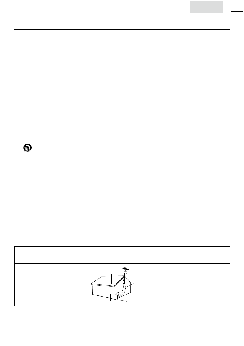
Note to the CATV system installer : This reminder is provided to call the CATV system installer’s attention to Article
820-40 of the NEC that provides guidelines for proper grounding and, in par ticular, specifies that the cable ground shal
be connected to the grounding system of the building, as close to the point of cable entry as practical
Example of Antenna Grounding as
per NEC - National Electric Cod
ELECTRIC SERVICE EQUIPMENT
ROUND CLAMP
NTENNA LEAD IN WIR
NTENNA DISCHARGE UNIT (NEC SECTION 810-20
ROUNDING CONDUCTORS (NEC SECTION 810-21)
ROUND CLAMP
OWER SERVICE GROUNDING ELECTRODE SYSTEM (NEC ART 250, PART H
Page 4
4
CC WARNIN
G
E
g
a
Y
Trade N
.
l:
Add
.
Teleph
T
7
Th
a
N
Like all LCD products, this set contains a lamp with Mercury, please dispose of according to all Local, State and
v
G
d
.
.
W
.
.
T
E
.
A
.
.
G
.
A
.
I
.
.
.
G
.
.
.
.
This apparatus may generate or use radio frequency energy. Changes or modifications to this apparatus may cause harmful interference
unless the modifications are expressly approved in the manual. The user could lose the authority to operate this apparatus if an
unauthorized change or modification is made.
ADIO-TV INTERFERENC
This apparatus has been tested and found to comply with the limits for a Class B digital device, pursuant to Part 15 of the FCC Rules.
These limits are designed to provide reasonable protection against harmful interference in a residential installation. This apparatus
enerates, uses, and can radiate radio frequency energy and, if not installed and used in accordance with the instructions, may cause
harmful interference to radio communications. However, there is no guarantee that interference will not occur in a particular installation.
If this apparatus does cause harmful interference to radio or television reception, which can be determined by turning the apparatus off
nd on, the user is encouraged to try to correct the interference by one or more of the following measures:
) Reorient or relocate the receiving antenna.
2) Increase the separation between the apparatus and receiver.
3) Connect the apparatus into an outlet on a circuit different from that to which the receiver is connected.
4) Consult the dealer or an experienced radio/TV technician for help.
DECLARATION OF CONFORMIT
ame:MAGNAVOX
2MD311B / 32MD301B
ode
26MD311B / 26MD301B
22MD311B / 19MD311B / 19MD301B
esponsible Party:UNAI CORPORATION, Inc
ress:9900 Van Ness Avenue, Torrance, CA 90501 U.S.A
one Number:1-866-341-3738
his Class B digital apparatus complies with Canadian ICES-003. Standard Television Receiving Apparatus, Canada BETS-7 / NTMR-
AUTION :
WARNING :
Danger of explosion if battery is incorrectly replaced. Replace only with the same or equivalent type.
Batteries (battery pack or battery installed) shall not be exposed to excessive heat such as sunshine, fire or the like.
Disconnect the mains plug to shut off when find trouble or not in use. The mains plug shall remain readily operable.
is apparatus should not be placed in a built-in installation such as a bookcase or rack unless proper ventilation is provided.
Make sure to leave a space of 4 inches (10cm) or more around this apparatus.
WARNING: To prevent injury, this apparatus must be securely attached to the wall in accordance with the instructions.
Do not place the unit on the furniture that is capable of being tilted by a child and an adult leaning, pulling, standing or
climbing on it. A falling unit can cause serious injury or even death.
ASER SAFETY
This apparatus is classified as a CLASS 1 LASER PRODUCT. This apparatus employs a
aser. Only a qualified service person should remove the cover or attempt to service this
pparatus, due to possible eye injury.
AUTION: Use of controls or adjustments or performance of procedures other than
those specified herein may result in hazardous radiation exposure.
IMPORTANT COPYRIGHT INFORMATIO
Unauthorized copying, broadcasting, public performance and lending of discs are prohibited. This item incorporates copy
protection technology that is protected by U.S. patents and other intellectual property rights of Rovi Corporation.
everse engineering and disassembly are prohibited.
Federal laws. For the disposal or recycling information, contact:
www.mygreenelectronics.com or www.eiae.org
The American Academy of Pediatrics discourages television
iewing for children younger than two years of age.
NOTE ABOUT RECYCLIN
This unit’s packaging materials are recyclable and
can be reused. Please dispose of any materials in
accor
ance with your local recycling regulations
Batteries should never be thrown away or
ncinerated but disposed of in accordance with your
ocal regulations concerning chemical wastes
or product recycling information, please visit - www.magnavox.com
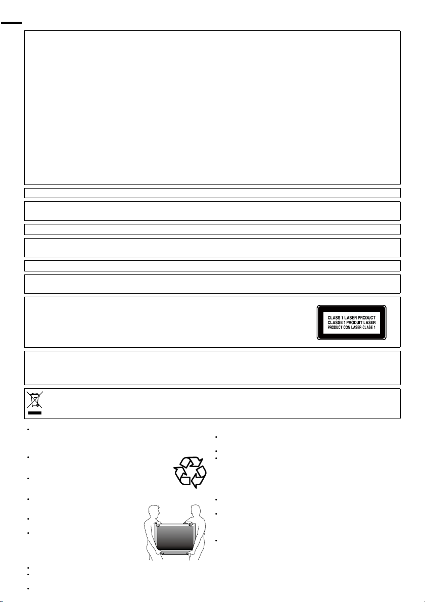
HEN CARRYING THIS UNIT
At least 2 people are required when
carrying this unit
ake sure to hold the upper and bottom
frames of the unit fi rmly as illustrated
O AVOID THE HAZARDS OF
ELECTRICAL SHOCK AND FIR
Do not handle the AC power cord with wet hands
Do not pull on the AC power cord when disconnecting it from an
C outlet. Grasp it by the plug
Do not put your fi ngers or objects into the unit
OCATION AND HANDLIN
o not install the unit in direct sunlight or in a place subject to dust
r strong vibration
void a place with drastic temperature changes
nstall the unit in a horizontal and stable position. Do not place
anything directly on top or bottom of the unit. Depending on your
external devices, noise or disturbance of the picture and / or sound
may be generated if the unit is placed too close to them. In this case,
please ensure enough space between the external devices and the
unit
Depending on the environment, the temperature of this unit may
ncrease slightly. This is not a malfunction
Be sure to unplug the AC power cord from the AC outlet before
moving or carrying the unit
DEW CONDENSATION WARNIN
Dew condensation may form inside the unit in the following
onditions. If so, do not use this unit at least for a few hours until its
nside gets dry
- The unit is moved from a cold place to a warm place
- Under conditions of high humidity
- After heating a cold room
Page 5

h
Child Safety
nglis
Page 6

INTRODUCTION
t
.
.
.
©
.
A
t
w
.
igh
bligati
.
with the
trad
hibited
g
A
.
3
T
7
A
9
T
9
9
T
2
A
3
4
4
T
7
7
T
1
2
7
7
9
1
1
1
1
1
2
Z
2
2
3
3
3
3
4
4
9
T
2
3
3
4
4
7
Trademark Information
Contents
Important Safety Instructions
hild Safety 5
INTRODUCTION
rademark Information 6
eatures
upplied Accessories 8
ymbols Used in this Manual 8
ttaching the Base 8
Mounting the Unit on Your Furniture
ilt Stand
22MD311B / 19MD311B / 19MD301B only>
Installing the Batteries
ontrol Panel 10
erminals 10
Remote Control Function 1
PREPARATION
ntenna Connection 1
onnection to Cable Receiver or Satellite Box 1
lug In the AC Power Cord 1
Initial Setup 15
WATCHING TV
leep Timer 16
witching Each Input Mode 16
reeze Mode 16
hannel Selection 16
V Screen Display Mode 1
ound Functions 1
V Screen Information 18
USING FUNCTIONS
icture 20
ound 20
hannel 2
eatures 2
Language 2
DVD 2
Language Code List 2
OPERATING DVD
layable Media 30
nplayable Media 30
layback 3
Disc Menu 3
Resume Playback 3
aused and Step-by-step Playback 3
ast Forward / Fast Reverse 3
low Forward / Slow Reverse 3
oom 3
earch Functions 3
Repeat Playback 3
Repeat A-B Playback 3
Random Playback 3
rogrammed Playback 3
n-screen Display 3
pecial Settings 3
CONNECTING DEVICES
External Device Connection 36
able Management
32MD311B / 32MD301B / 26MD311B / 26MD301B only> 3
USEFUL TIPS
roubleshooting Guide 40
AQ 4
INFORMATION
lossary 4
Maintenance 4
eneral Specifi cations 4
ther Specifi cations 4
Limited Warranty 4
HDMI, the HDMI Logo, and High-Defi nition Multimedia Interface are
rademarks or registered trademar ks of HDMI Licensing LLC in the
nited States and other countries
ouble-D symbol are trademarks of Dolby Laboratories
is a trademark of DVD Format/Logo Licensing Corporation
2011 Funai Electric Co., Ltd
ll rights rese rved. No par t of this manual may be reproduced, copied,
ransmitted, disseminated, transcribed, downloaded or stored in any
storage medium, in any form or for any purpose without the express prior
ritten consent of Funai. Furthermore, any unauthorized commercial
istribution of this manual or any revision hereto is strictly prohibited
Information in this document is subject to change without notice . Funai
reserves the r
otify any person or organization of such changes
o., Ltd. and may not be used in any way without the express written
onsent of Funai. All other trademarks used herein remain the exclusive
propert y of their r espec tive owners . Nothing contained in this manual
should be constr ued as granting, by implication or otherwise, any license
r right to use any of the t rademark s displayed herein. Misuse of any
emarks or any other content in this manual is strictly pro
unai shall aggressively enforce its intellectual propert y rights to the
fulles t extent of the law.
MAGNAVOX is a re
merica Corporation and is used by Funai Electr ic Co. Ltd . and Funai
orporation, Inc. under license fr om Philips Electronics Nor th America
t to change the content herein without the o
design is a regis tered trade mark of Funai Electric
istered trademark of Philips Electronics Nor th
on to
.
Page 7

Features
Y
,
.
DTV
.
A
Thi
y
.
k
T
.
.
A
.
A
ill
.
.
:
.
l.
V
d
.
f
the HDMI
TV.
t
t
t
A
t
t
DVI I
t
W
.
A
t
y
DVI I
t
.
t
t
d
Enjoy Dolby Digital
.
DVD M
Y
DVD-video.
y
s
.
k
.
k
s
d.
n
Y
.
k
Y
DVD-video.
Y
s
.
.
t
d
The p
k.
t
de
D
Y
D
.
k
.
INTRODUCTION
DTV / TV / C ATV
ou can use your remote control to select channels which are
broadcast in digital format and conventional analog format. Also
able subscribers can access their cable TV channels
Information Display (ATSC only)
You can display the title, contents and other information of the
urrent
utoprogram
our area, eliminating diffi cult setup procedures
hild Loc
programs
losed Caption Decoder
Built-in closed caption decoder displays text for closed caption
supported programs
MTS / SAP Tuner
uto Standby
If there is no input signal and no operation for 15 minutes, the
unit w
Sleep Timer
You can set the unit to go into standby mode after a specifi c
amount of time
hoices for On-screen Language
English, Spanish or French
program on the TV screen
s unit automatically scans and memorizes channels available in
his feature allows you to block children’s access to inappropriate
udio can be selected from the remote control
go into standby mode automatically
elect your on-screen language
Stereo Sound Function
LL Frequency Synthesized Tuning
rovides free and easy channel selection and lets you tune
irectly to any channel using the number and decimal point “•”
uttons on the remote contro
arious Adjustment for Picture and Soun
ustomizes image quality suitable for your room and sets your
sound preference
un-Link via HDMI Link (HDMI Cable not Included)
fun-Link allows your other HDMI link devices to be controlled by
cable connected to your
Inpu
omponent Video Inpu
S-Video Inpu
V Inpu
Digital Audio Outpu
2MD311B/
monitor if your PC has a DVI output terminal
2MD301B / 26MD311B/ 26MD301B only
-
npu
hen using HDMI 1 Input, you can enjoy this unit as a PC
nalog Audio outpu
22MD311B /
If your video device has DVI output jack, use an HDMI-DVI
onversion cable to connect the unit
9MD311B / 19MD301B onl
-
npu
C Inpu
Headphone Audio Outpu
Dolby Digital Soun
onnect the unit to your Dolby Digital decoder.
Still / Fast / Slow / Step Playback
Various playback modes are available including still pictures, fast
forward/reverse, slow motion and step frames
ou can display DVD menus in a desired language, if available on
a
Auto standb
If there is no operation for 20 minutes, the unit will go into
tandby mode automatically
Parental Loc
Block the viewing of a DVD-video unsuitable for children
Resume Playbac
Lets you resume playback from the point at which playback was
toppe
it Rate Indicatio
DRC (dynamic range control)
ou can control the range of sound volume
Accessing from MODE
multi-channel surround sound when you
enus in a Desired Language
utton
uring playbac
Subtitles in a Desired Language
ou can select a desired language for displaying subtitle, if that
anguage is available on a
Selecting a Camera Angle
ou can select the desired camera angle, if a DVD contains
equences recorded from different angles
Zoom
Allows you to enlarge the size of picture image
Black Level Adjustmen
Virtual Surroun
Search
chapter search / title search / track search / time search
rker
art on the disc designated by user can be called bac
epea
chapter / title / track / all / A-B
Accessing from
ODE button
n stop mo
Program Playback for audio C
ou can program the order of tracks to play them back in
esignated order.
Random Playback for audio C
This unit can shuffl e the order of tracks to play them back in
randomly
Accessing from AUDIO button
uring playbac
Choices for Audio Language and Stereo Sound Function
Select your desired languages or stereo sound function when
ifferent options are available on your disc
PREPARATION WATCHING TV
USING FUNCTIONS OPERATING DVD
CONNECTING DEVICES
INFORMATION USEFUL TIPS
Page 8
8
s
t
d
s
AAA
AAA
TV b
s
l
y
2
.
.
.
ls.
T
p
:
T
.
D FUNCTION
S
D
h.
Y
.
.
➀
), then move the
h
p
ligned. Mak
FRONT
t
.
Philli
il th
.
Phillips head
A
t
.
W
t
.
.
.
W
.
Supplied Accessorie
wner’s Manual
Remote Control
NF801UD)
atterie
AAA, 1.5V x 2)
Note
f you lose the screws, please purchase the above-mentioned
ps head screws at your local store
If you need to replace these accessories, please refer to the part
name and No. with the illustrations and call our toll free customer
support line found on the cover of this manual
When using a universal remote control to operate this unit.
ake sure the component code on your universal remote control
s set to our brand. Refer to the manual accompanying your
remote control for more details
We do not guarantee 100% interoperability with all universal
remote contro
uick Start Guide
If you have any questions, please visit our website at
www.
magnavox.com/suppor
Quick
Start
EN
Installation
FR
Installation
ES
Instalación
Best
Better
Good
egistration car
ase and screw
Screws packed with this unit:
ode
2MD311B
2MD301B
26MD311B
26MD301B
22MD311B
9MD311B
9MD301B
Size
M4 x 20
M4 x 1
Symbols Used in this Manual
he following is the description for the symbols used in this
manual. Descri
V FUNCTIONS
ATS C
NTSC
If neither symbol appears, the operation is applicable to both
tion refers to
: Digital TV operation
: Analog / Cable TV operation
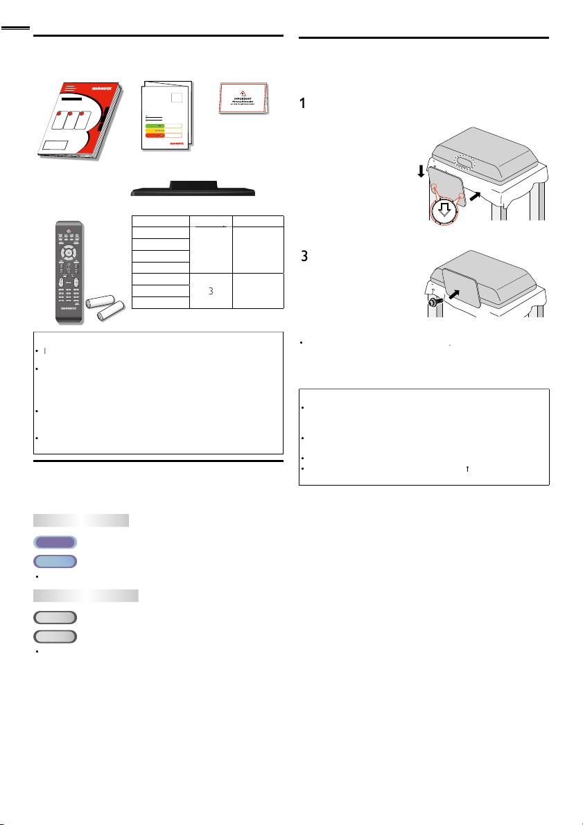
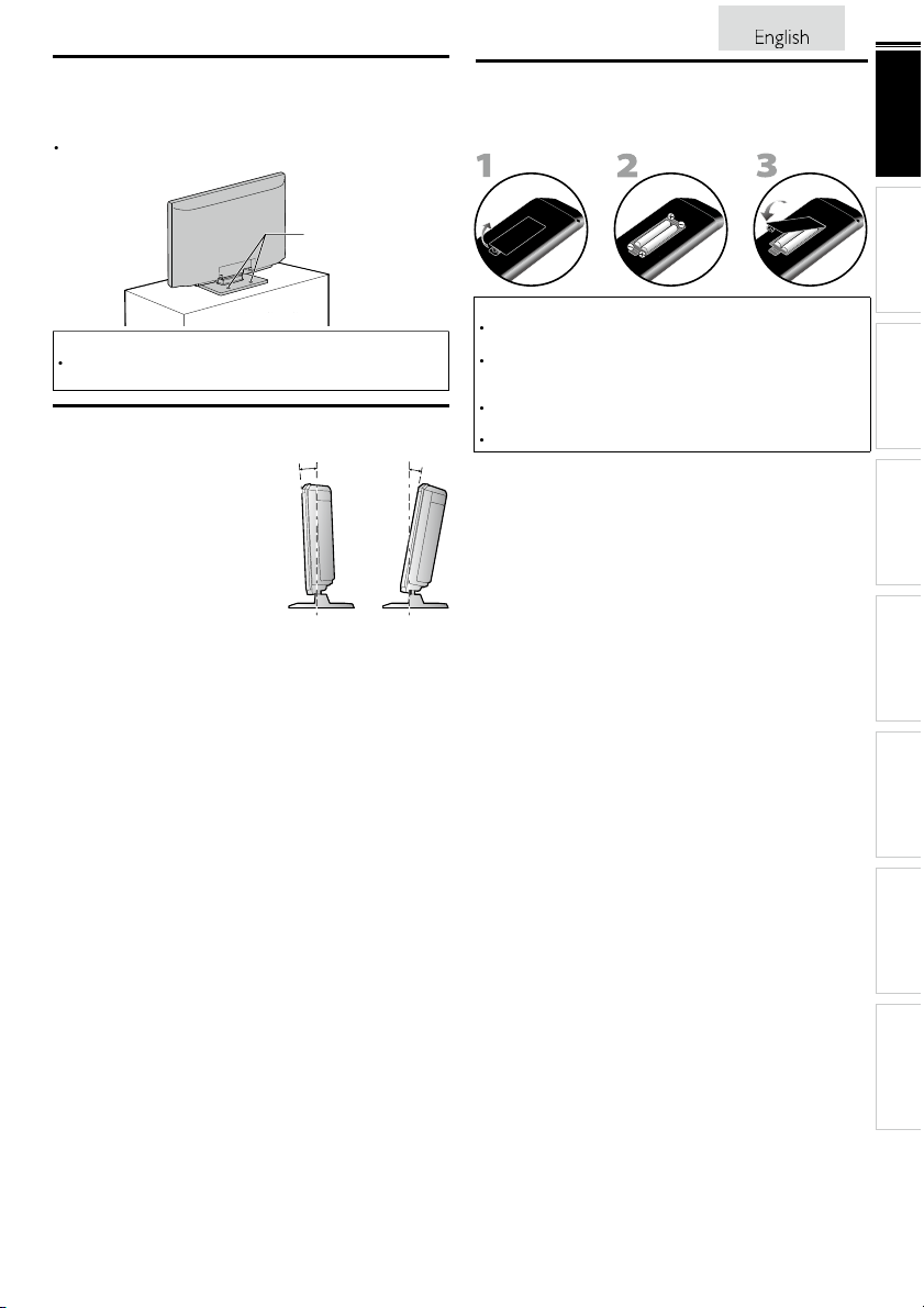
Attaching the Base
ou must attach the base to the unit to have it as a table top
nit. Be sure the front and rear of the base match the proper
irection. At least 2 people are required for these steps
Spread a thick and soft cloth over a table as shown at step 2
lace the main unit face down onto it. Make sure not to
amage the screen.
Insert 2 hooks under the
ottom of the main unit
nto base holes (shown by
arrow
ase in the direction as
s
own by arrow ➁until it
sto
s and the screw holes
are a
e sure not
o put the AC power cord between the base and the unit
Drive
ps head screws
nto the threaded holes
at the bottom of the base
unt
ey are tight
To remove the base from this unit
nscrew the
fter the screws are removed, move the base in the opposite direction
as shown by arrow in step 2, then pull the base up toward the rear of
he unit. Be careful not to drop the base when you remove it
screws in step 3
Note
hen attaching the base, ensure that all screws are tightly fastened. If
he base is not properly attached, it could cause the unit to fall, resulting
n injuries as well as damage to the unit
Make sure to use a table which can support the weight of this unit and
s larger than this unit
ake sure the table is in a stable location
hen attaching the base, ensure that FRONT
pward. If it’s not upward, the 2 hooks don’t fi t in the base
written on the base is
DVD
CD
If neither symbol appears under the function heading, operation is
applicable to bot
: Playback of DVD-video
: Playback of audio C
Page 9
ounting the Unit on Your Furniture
.
screw holesscrew holes
Wh
d
.
Y
t
.
10°
2.5
-2.5°
.
AAAAAAAAA
AAA
AAAAAA
.
.
.
.
crew this unit on your furniture tightly using wood screws
not supplied) in the 2 holes at the back of the base as shown
Recommended screw dimension : 0.201 x 0.788 inches (5.1 x 20 mm)
Note
en you remove this unit make sure to unscrew the woo
screws from your Wood Stand, Furniture and other wood item
Tilt Stand
ou can adjust the stand to change
he angle of the unit (-2.5° to 10°)
22MD311B / 19MD311B / 19MD301B only>
Installing the Batteries
Install the batteries (AAA, 1.5V x 2) matching the polarity
ndicated inside battery compartment of the remote control
Battery Precautions:
Be sure to follow the correct polarity as indicated in the battery
ompartment. Reversed batteries may cause damage to the device
Do not mix different types of batteries together (e.g. Alkaline and
arbon-Zinc, or rechargeable batteries like ni-cad, ni-mh, etc) or old
batteries with fresh ones
If the device is not to be used for a long period of time, remove the
batteries to prevent damage or injury from possible batter y leakage
o not try to recharge batteries; they can overheat and rupture
9
INTRODUCTION
PREPARATION WATCHING TV
USING FUNCTIONS OPERATING DVD
CONNECTING DEVICES
INFORMATION USEFUL TIPS
Page 10
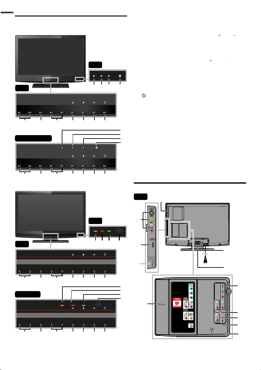
Control Panel
s
7
(
)
()th
.
(
)
(
)
th
.
A
1
1
1
5
.
T
d.
d.
r
dby
.
.
w
l.
s
MD311B serie
32”
MENU
−VOLUME
+
1 2 3 4 5 6 7
26”/22”/19”
−VOLUME
+
1 2 3 4 5 6 7
MENU
−CHANNEL
−CHANNEL
+
DVD
+
32”
DVD
8 9 10 11
POWER
POWER
1 VOLUME + / −
ress to adjust the volume or move right
rough the main menu items
HANNEL + / −
3
ress to select channels or move up
rough the main menu items
(eject)
C (stop)
B (play)
POWER
ress to turn the unit on and go into standby mode
o completely turn off the unit, you must unplug the AC
power cor
8
ghts up orange when a disc is inserte
8
9 STAND BY indicato
9
10
10
11
11
0
OWER ON indicator
Infrared sensor windo
Receives infrared rays transmitted from the remote
ontro
indicator
ts up red when the unit goes into stan
ts up green when power is on
p. 1
/ left
p. 19
p. 16
/ down
p. 3
p. 3
p. 3
p. 1
mode
MD301B serie
32”
MENU
−VOLUME
+
−CHANNEL
+
1 2 3 4 5 6 7
26”/19”
STAND BY POWER ON
MENU
−VOLUME
+
1 2 3 4 5 6 7
DVD
−CHANNEL
+
32”
STAND BYPOWER ON
DVD
8 9 10 11
POWER
POWER
8
9
9
10
10
11
11
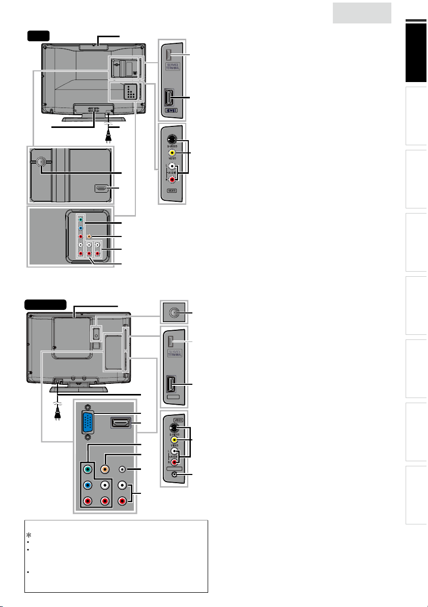
Terminals
32”
13
12
*
22
14
15
16
17
DVI
ANALOG
AUDIO
18
19
20
21
Page 11
glish
26”
s
f
l
1
4
s
7
s
1
A
.
W
,
ll.
A
.
W
,
y
HDMI 2
HEAD PHONE
HDMI 2
HEAD PHONE
.
.
T
s
t
.
f
k
.
l
1
4
s
7
A
.
1
A
.
22”/19”
Note for service terminal
service terminal (service use only)
as digital camera, keyboard, mouse, etc. (because these will not
work)
he software update is, in most cases, handled by an authorized
ervice person or in some circumstances the user may be asked
o do the software update themselves
14
*
12
16
se this terminal only when a software update is necessary
ser should not connect any devices to the service terminal such
15
13
21
22
17
20
19
18
16
16
17
18
19
19
20
20
21
21
22
22
23
23
HDMI 2
HDMI 2
HEAD PHONE
HEAD PHONE
15
15
12
12
13
13
14
14
*
*
n
32MD311B /
Side Panel
HDMI 2 Input jack
3 S-Video / Composite Video / Audio (L/R) Input jack
or VIDEO
ear Pane
isc loading slot
5 AC power cord
6
able management
7 Component Video and Audio (L/R) Input jack
8 Analog Audio (L/R) Output jack
9 Analog Audio (L/R) Input jacks for HDMI
nput jack
udio cable connection from a DVI device
se a stereo mini plug conversion cable as we
(For HDMI 1 Input jack only)
20 Digital Audio Output jack
ntenna Input jack
21
HDMI 1 (HDMI-DVI) Input jack
HDMI connection for HDMI or DVI device
ou can enjoy this unit as a PC monitor.
22MD311B /
Side Panel
HDMI 2 Input jack
3 S-Video / Composite Video / Audio (L/R) Input jacks
or VIDEO
4 Headphone Audio Output jac
Headphone connection for personal listening
ear Pane
5 Antenna Input jack
6 Disc loading slot
7 AC power cord
8 PC (VGA) Input jack
9 HDMI 1 (HDMI-DVI) Input jack
20 Component Video and Audio (L/R) Input jack
Digital Audio Output jack
nalog Audio (L/R) Input jack for PC connection
Mini-plug audio cable connection from PC
23 Analog Audio (L/R) Input jacks for HDMI
nput jack
udio cable connection from a DVI device
(For HDMI 1 Input jack only)
2MD301B / 26MD311B / 26MD301B>
p. 14, 36
p. 37, 38
p. 3
p. 1
p. 39
p. 14, 3
p. 39
p. 36, 39
hen you connect your PC that has a DVI terminal
p. 38
p. 13
p. 14, 36, 39
hen you connect your PC that has a DVI terminal
9MD311B /
9MD301B>
p. 14, 36
p. 37, 38
p. 13
p. 3
p. 1
p. 39
p. 14, 36
p. 14, 3
p. 38
p. 39
p. 36
INTRODUCTION
PREPARATION WATCHING TV
USING FUNCTIONS OPERATING DVD
CONNECTING DEVICES
INFORMATION USEFUL TIPS
Page 12
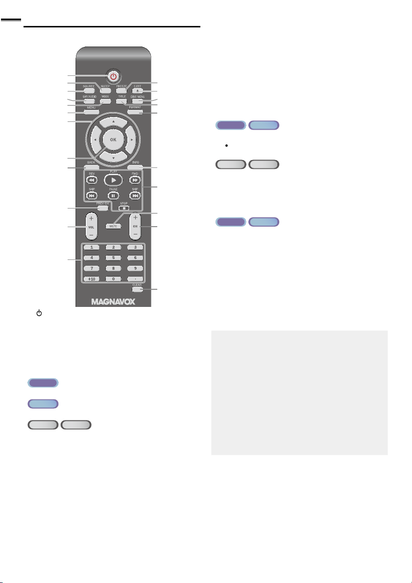
Remote Control Function
5
dby
.
T
d.
7
.
.
(CD).
E
7
.
.
g play
).
.
.
.
.
K
l.
7
.
.
ly.
.
.
A
1
.
1
.
TITLE
1
).
7
.
4
D
1
.
B
1
k.
G
.
F
1
k.
C
1
k.
7
.
.
).
1
2
2
3
4
5
6
7
8
9
10
11
12
(power)
ress to turn the unit on and go into stan
o completely turn off the unit, you must unplug the AC
ower cor
SLEEP
SOURCE
SAP / AUDIO
ATS C
ress to select the audio language
NTSC
ress to select the audio mode
DVD CD
ress to select the audio language (DVD), or sound
mode
MOD
ress to arrange the playing order or playback
randomly (CD)
ress to set the black level (DVD) and the virtual
surround on or off
ress to change the camera angle to see the sequence
ed back from different angle (DVD
bein
ress to search chapter, title (DVD), track (CD) or time
ress to set the marker.
ress to repeat playback chapter, title (DVD), track, disc
CD) repeatedly or between designated point A and B
ress to magnify the part of picture (2x and 4x : DVD)
ress to select the subtitles on a disc (DVD)
➠
➠
p. 1
p. 16
p. 16
p. 1
p.
13
14
15
16
17
18
19
20
21
22
mode
➠
▲/▼/◄/►(cursor)
8
9 BAC
0
REV CH
ress to return to the previously viewed channe
1 VOL + / −
2
umber buttons
ATS C
NTSC
ress to select channels
➠
p. 19
p. 15
p. 15
p. 18
p. 16
p. 1
p. 16
(dot)
ress to shift the subchannel from the main channel
DVD CD
ress to select chapter, title (DVD), or track (CD)
rect
+10 button
ress to select 10 or higher number of chapters
3
5 DISC MENU
6
7 FORMAT
8 INFO
9
20
ATS C
NTSC
ress to pause screen image
EJECT
ress to eject the disc
ress to display the menu on a disc
ress to display the title menu (DVD
p. 16
p. 3
p. 3
p. 3
p. 1
ress to select aspect ratio available for the TV screen
p. 18, 3
E/ FWD
uring the pause mode (DVD) and search backward or
forward through a disc
LAY
ress to begin the disc playbac
SKIP H/ SKIP
r tracks (CD) of the disc
AUSE
ress to pause the disc playbac
STOP
ress to stop the disc playbac
H + / −
LEAR
ress to clear the numbers entered incorrectly
ress to cancel the point A for A-B repeat
ress to remove the track number in program input
CD
p. 3
p. 3
p. 32
p. 3
p. 3
p. 1
p. 16
p. 32, 33
Page 13
h
REPARATION
plugging
.
.
VHF / UHF VHF / UHF
analog
analog
or
cable TV signalcable TV signal
ca
VHF / UHFVHF / UHF
analog
analog
or
ca
ca
cable TV signalcable TV signal
i
]
5
w
.
t
.
.
w
.
T
ily b
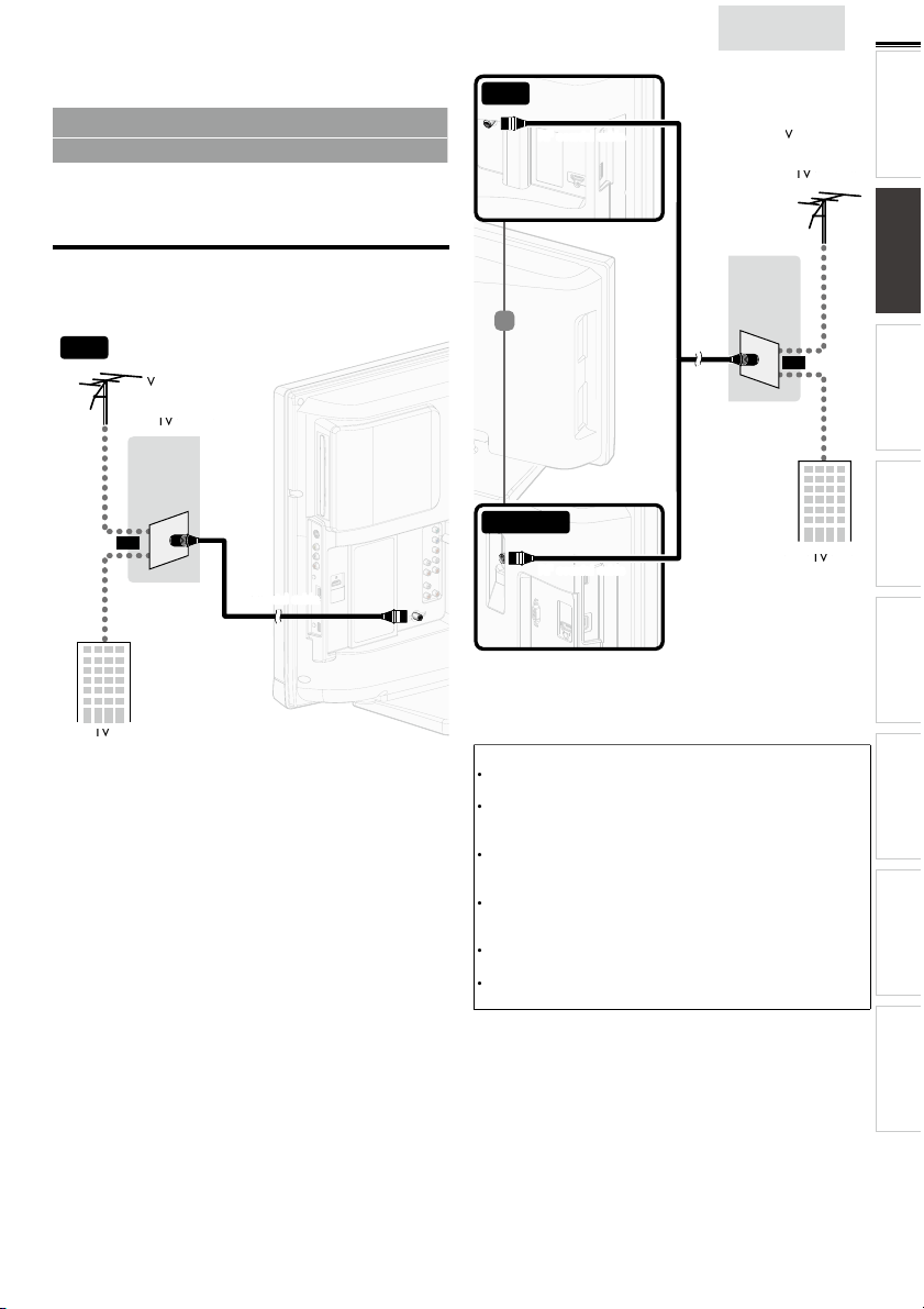
No supplied cables are used with these connections:
• Please purchase the necessary cables at your local store.
Before you connect:
e sure your antenna or other device is connected properly
before
Antenna Connection
onnect the RF coaxial cable on your home outlet to the
antenna input jack of this unit
32”
in the AC power cord
26”
nglis
13
INTRODUCTION PREPARATION
WATCHING TV
or
USING FUNCTIONS OPERATING DVD
or
22”/19”
nce connections are completed, turn on the unit and begin
nitial setup. Channel scanning is necessary for the unit to
memor
ze all available channels in your area.
p. 1
Note
If you have any question about the DTV’s antenna, visit
ww.antennaweb.org for further information
Depending on your antenna system, you may need different types
f combiners (mixers) or separators (splitters) for HD TV signal
he minimum RF bandpass on these devices is 2,000MHz or 2GHz
For your safety and to avoid damage to this unit, please unplug the
RF coaxial cable from the antenna input jack before moving the
unit
If you did use an antenna to receive analog TV, it should also
ork for DTV reception. Outdoor or attic antennas will be more
effective than a set top or inside antenna
o switch your reception source eas
nstall an antenna selector.
If you are not receiving a signal from your cable service, contact the
able provider.
Initial Setup
etween antenna and cable,
CONNECTING DEVICES
INFORMATION USEFUL TIPS
Page 14
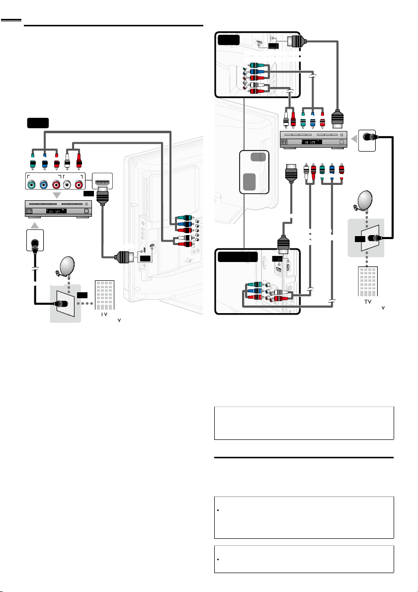
onnection to Cable Receiver or
.
jacks for the Component Video connector jacks.
(red)
(blue)
(green)
cable receiver /cable receiver /
satellite boxsatellite box
cable TV signalcable TV signal
component video cablescomponent video cables
ca
c
satellite dishsatellite dish
(red)
(blue)
(green)
(red)
(blue)
(green)
cable receiver /cable receiver /
satellite boxsatellite box
cable TV signalcable TV signal
component video cab
component video cables
a
component video
component video
cables (red / blue /
cables (red / blue / green)
aud
and audio cables
ca
satellite dishsatellite dish
Y
lli
.
d
.
t
).
.
Each ti
.
Satellite Box
se an HDMI or Component Video cables to connect the
HDMI or the Component Video Input jacks of the unit to the
HDMI or the Component Video output jacks of the cable
receiver / satellite box
If you connect to the unit’s Component Video Input jacks,
onnect Analog Audio cables to the Analog Audio L/R Input
32”
26”
or
STEREO
PCM
ANT IN
COMPONENT VIDEO OUT
ANT IN
AUDIO OUT
Pr/CrPb/CbY
HDMI OUT
RL
or
STEREO
PCM
or
or
22”/19”
or
or
ou can also connect this unit to the cable receiver or sate
te
ox other than the HDMI or the Component Video output jacks
r Composite Video output jack (p. 37, 38) because they
might have different output jacks
Required cables and connecting methods of the cable receiver /
atellite box, or the availability channel for the clear QAM may
iffer depending on the cable / satellite provider or local TV
roadcaster.
or more information, please contact your cable / satellite provider
r local TV broadcaster.
Note
• Use an HDMI cable with the HDMI logo (a certifi ed HDMI cable).
High Speed HDMI cable is recommended for the better
compatibility.
lug In the AC Power Cor
Make sure that the AC power cord must be plugged to an AC
utlet after all the necessary connections are made
Caution:
Do not connect the AC power cord to a power supply outside
he indicated voltage of this unit (AC 120V
onnecting the AC power cord to a power supply outside of this
range may result in fi re or electrical shocks
Note
me you
erformed for a few seconds. This is not a malfunction
lug in the AC power cord, no operations will be
Page 15
h
These operations are accessible by remote control.
p
T
lly
.
:
.
,
to turn on the unit.
.
it i
.
U
TV
]
ill begin.
U
ill b
y
t
t
.
f
the l
ill be displ
.
]
ill
.
t
ill b
d.
T
1
.
A
.
]
1
.
]
.
]
7
g.
]
Some may also be accessible by controls on the main unit.
nglis
se
/► to select the desired location setting, then press
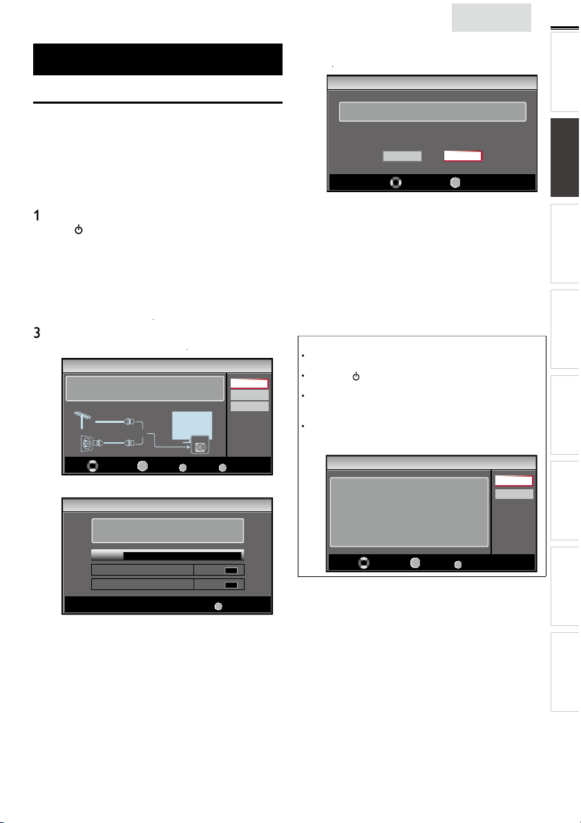
Initial Setup
INTRODUCTION PREPARATION
Initial Setu
his section will guide you through the unit’s initial setting
which includes selecting a language for your on-screen menu
and autoprogram, which automatica
viewable channels
Before you begin
ake sure the unit is connected to antenna or cable
After making all the necessary connections
ress
It may take a few moments to turn on the unit for the
first time
Initial Setup]menu appears automatically after the
s turned on
un
2
se ▲/▼ to select the on-screen language from the
hoices (English / Español / Français) on the right side of the
screen, then press
Use ▲/▼ to select
for CATV channels, then press
Initial Setup
Make sure the antenna is connected to ''ANT. IN'' jack.
Select your signal source.
Antenna
Cable
utoprogram]w
Initial Setup
Please wait while the system is scanning for channels.
Auto programming may take more than 20 minutes to
complete.
Digital channels
Analog channels
ntenna]for TV channels or
Or
OK
Select
0%
scans and memorizes
ANT.IN
BACK
OK
Back
0 ch
0 ch
Cable
Antenna
Cable
Skip
MENU
Skip
MENU
Skip
Select “Retail” or “Home” for your location.
Retail
elect
etail] store, the unit w
redefined setting for retail displays.
elect
for home setting and it can be adjusted
efficienc
hrough a choice of picture and sound quality according
o your preference
When the initial setup is completed, the lowest
memorized channel with the confirmation message o
ocation setting w
You must set
and
Sound]settings you adjusted w
memorized after the unit goes into standby mode
Select
ome], the unit is set to maximize the energy
ome] in step4. Otherwise,
Home
OK
OK
e set up with
ayed on the TV screen
not be
Note
If you are not receiving a signal from your cable service, contact
he Cable provider.
If you pressor
annels w
he initial autoprogram function can be executed for either
ntenna]or
onnection (Antenna / Cable), set
If there is no signal input from the antenna terminal and no
eration for several seconds after you turn on the unit, helpful
nts appears. Follow the instructions listed on the TV screen
Initial Setup
No channel is registered.
Try Autoprogram again?
Verify that you have a cable connected to the “ANT. IN” jack
on the back of the TV, the channel installation process
searches this connection. If you are using a cable or satellite
box, please confirm the input which you have connected to the
box and press “SOURCE” key on the remote control to select
the appropriate source input.
fter an initial setup is completed...
If you want to scan the channels automatically again
utoprogram
during autoprogram, this setup of TV
e cancele
Cable] only once. When you change the
Select
utoprogram]again.
OK
OK
MENU
Skip
p. 2
Retry
Later
You can add the desired cable and analog channels
nmemorized by autoprogram
Add Channels
p. 22
If you want to change to another language
anguage
p. 2
If you want to change the location settin
ocation
p. 26
icture
p. 2
WATCHING TV
USING FUNCTIONS OPERATING DVD
CONNECTING DEVICES
INFORMATION USEFUL TIPS
Page 16

6
p
t
).
.
T
d.
il
l
.
.
)
.
These may differ depending on what product you purchased. For example, 22MD311B,
g
pp
d.
g
.
.
Th
ill
d.
T
s
T
,
T
,
ATS C
W
1
NTSC
W
1
l.
ill app
l.
WATCHING TV
Sleep Time
ress SLEEP repeatedly to change the amount of time (increases
he time by 30 minutes up to 120 minutes
ress SLEEP once to call up the display for checking the remaining time
o cancel sleep timer, press SLEEP repeatedly until
splaye
Switching Each Input Mode can eas
between TV (ATSC or NTSC) and external devices when they are connected to the unit
ress SOURCE H
e.g.) 32MD311B/32MD301B/26MD311B/26MD301B
Source
TV
Video
Component
HDMI1
HDMI2
ressingH − reverses the direction of the input modes
9MD311B or 19MD301B will be displayed
reeze Mode can freeze the ima
ress
to freeze the image
e sound output w
o cancel freeze mode, press any buttons except
repeatedly to cycle through the input modes
11.1
DTV / TV channel
Freeze
not be pause
HDMI2 HDMI1
HDMI 1]
e shown on the TV screen for 5 minutes
Sleep Off] is
y switch with the remote contro
Video Component
HDMI 2]andPC] instea
Sleep 120min.
PC input
hannel Selection
elect channels by using
o select the memorized channels
use
H + / − or the Number buttons.
o select the non-memorized channels
use the Number buttons.
H + / − or the Number button
11.1
use the Number buttons
hen selecting digital channel 11.
Be sure to press • before entering the subchannel number.
hen selecting cable or analog channel 1
ress
REV CH to return to the previously viewed channe
Note
[No Signal] will appear on the TV screen after the subchannel
roadcast is over.
udio only program]message w
receive only sound signa
ear on the TV screen, when you
Page 17

n
glish
.
dly
.
F
l
l
.
.
d
v
.
Z
with
.
Wid
Thi
.
l
Wid
d
Z
F
l
l
.
.
d
t
t
.
Z
.
Wid
displ
th
.
l
Wid
d
Z
F
l
.
ll
.
t
.
l
t
ll
.
s
.
j
j
j
j
j
j
j
j
j
j
j
j
j
j
j
j
j
j
j
j
j
j
j
j
j
j
j
j
j
j
j
j
j
j
j
j
j
j
j
j
j
j
j
j
j
j
j
j
j
j
j
j
j
j
j
j
j
j
j
j
j
j
j
j
j
j
j
j
j
j
j
j
j
j
j
j
j
j
j
j
j
j
j
j
j
j
j
j
j
j
j
j
j
j
j
j
j
j
j
j
j
j
j
j
j
j
j
j
j
j
j
j
j
j
j
j
j
j
j
j
j
Volume Adjustment
e
.
.
.
.
w
.
g
g
g
g
g
g
g
g
g
g
g
g
g
g
g
g
g
g
g
g
g
g
g
g
g
g
g
g
g
g
g
g
g
g
g
g
g
g
g
g
g
g
g
g
g
g
g
g
g
g
g
g
g
g
g
g
g
g
g
g
g
g
g
g
g
g
g
g
g
g
g
g
g
g
g
g
g
g
g
g
g
g
g
g
g
g
g
g
g
g
g
g
g
g
g
g
g
g
g
g
g
g
g
g
g
g
g
g
g
g
g
g
g
g
g
g
g
g
g
g
g
g
g
g
g
g
g
g
g
g
g
g
g
g
g
g
ATS C
.
A
.
.
11.1
NTSC
W
th
l.
11
Wh
S
S
TV Screen Display Mode
5 types of display modes can be selected when the broadcasting station is sending 16:9 or 4:3 video signal. And 3 types of display
modes can be selected for PC input signal
ress FORMAT repeate
or 16:9 video signa
orma
or 4:3 video signa
orma
or PC input signal through
orma
or 22MD311B, 19MD311B and 19MD301B, PC input mode is available. They can only accept the PC input signal when the unit
s connected to a PC (VGA) Input jack
to switch the TV aspect ratio
4:3
e
6:9
e
HDMI1
u
Input mode
oom
oom
ovie expan
ovie expan
ot By Do
orma
isplays a 16:9 picture at its original size
4:3
isplays a 16:9 picture at a 4:3 size; the picture is
shortened horizontally. Sidebars appear on both edges
f the screen
ovie expan
ertically stretched to fi ll the screen. This only crops
ut the top of the picture
oom
out changing its horizontal and vertical ratio
e
rops out the left and right sides of the picture
orma
idebars appear on both edges of the screen
6:9 displays a 4:3 picture at a 16:9 size; the picture is
stretched horizontally to fi ll the screen
ovie expan
he picture is stretched more vertically at the top of
he screen. This crops out the top of the picture
oom displays a 4:3 picture at a 16:9 size; at its
maximum size that is more vertically stretched to fi ll the
screen. This crops out the top and bottom of the picture
e
riginal size and the edges stretched horizontally to fi ll
e screen
orma
idebars appear on both edges of the screen
u
displays a picture that is stretched out of
roportion horizontally to fi ll the screen
ot By Do
isplays a 16:9 picture that is
isplays a 16:9 picture at its maximum size
splays a horizontally stretched picture.
displays a 4:3 picture at its original size.
displays a 4:3 picture at a 16:9 size;
ays the picture with its center at the
displays a proportionately stretched picture.
displays a picture in its original size
INTRODUCTION
PREPARATION
s
WATCHING TV
USING FUNCTIONS OPERATING DVD
CONNECTING DEVICES
Sound Function
escribe how to change the audio or the audio language as well as the volume
se VOL + / − to adjust the volume
ilence Mod
ress
to turn off the sound temporarily
will be displayed for a few seconds
Mute
ress
again or VOL + / − to recover the original volume
Volume 30
ill be displayed for a few seconds when adjusting the volume
Switching Audio Mode
ress SAP/AUDIOrepeatedly to cycle through the available
audio languages
vailable languages differ depending on the broadcast
Other]s displayed when the audio language cannot be
acquired, or the acquired languages are other than English,
panish or French
English 1/3
ress SAP/AUDIO to display the currently selected audio mode.
hile receiving an MTS broadcast, press repeatedly to cycle
rough the available audio channe
SAP / STEREO SAP / MONO SAP / STEREO
TEREO: Outputs stereo-audio
AP : Outputs second audio program
MONO: Outputs mono-audio
SAP / STEREO
en all audio are available
hi!
salut!
hola!
INFORMATION USEFUL TIPS
Page 18

8
Y
.
id
d.
O
11-1
TV: TV-14
1080i
1080i
16:9
16:9HDHD
CC
CC
KABC
KABC
1 23 4
5
6, 7, 8
9
10
prog
prog
)
r
)
1
7
prog
(
]
)
hild lock
g
P
to hide the information.
▼
t
.
]
is displ
d.
d.
;
Vid
k.
T
.
TV Screen Information
ou can display the currently selected channel or other
nformation such as the audio mode on the TV screen
In the digital mode, the detailed broadcasting information
for the current off the air channel such as program title and
program gu
PressINF
ATS C
NTSC
es are displaye
A Day of Memories
A Day of Memories
A quarter-century ago,which may now qualify as the
good old days of newspapering,run-of-paper sales
accounted for 80 percent of the industry's advertising
revenues.Department stores and supermarket were
English 1/2
Rating
4
11
SAP / STEREO
480i
480i
TV-PG DLSV
5
4:3SDSD
4:3
6, 7, 8
CC
CC
9
10
ram title
ram guide
The program guide added to broadcasting
nformation is displayed to a maximum of 4 lines.
3broadcast station
channel numbe
5 audio language (ATSC) / audio mode (NTSC
Switching Audio Mode]p.
6effective scanning lines and scan mode
TV format
8
ram’s image aspect ratio
9 CC
not available if closed caption is set to
0 c
ratin
Off
2
ress INFOor
Note
When the program guide consists of more than 4 lines, use
o scroll to the next / previous lines
o description provided.
s not provide
While the program guide is displayed, the closed caption function
s interrupte
In external input mode, the following screen is displayed
e.g.) When an external device is connected to
ayed when the program guide
Video
SD
480i
SD
480i
CC
CC
TV-PG DLSV
he information display will automatically disappear in 1 minute
eo Input jac
/
Page 19

h
T
his section describes the overview of the main menu
T
.
th
.
to determine the setting.
e
S
d
ge
D
e
A
.
d
A
.
.
s
A
.
.
Y
DVD
.
.
splayed when you press
he main menu consists of the function setting items below
Press
e main menu
to display
ictur
oun
hannel
eatures
Langua
DV
nglis
Use ▲/▼ to select a desired menu and an item, then
ress
ictur
djusting the picture mode, or customize the
picture quality as your preference
oun
djusting the sound mode, equalizer and some
other sound functions
19
INTRODUCTION
PREPARATION WATCHING TV
USING FUNCTIONS
hannel
canning the channels available in your area and
see what the antenna levels are
eature
djusting the Closed Caption, parental guide and
some other useful functions
Langua
You can choose English, Spanish, or French
as your on-screen language
ou can choose the desired
When the setting is completed, press
settings
OPERATING DVD
CONNECTING DEVICES
INFORMATION USEFUL TIPS
to exit
Page 20

2
0
e
:
Y
]
in
]
.
S
d
C
ge
D
.
]
)
Y
.
igh
s
to i
igh
s
t
to d
r
to d
to i
Tint
t
d
t
t
t
T
e
t
s
t
s
d
:
Y
]
i
g
.
ure
C
ge
D
.
.
]
)
r
A
.
▼
t
dj
A
T
the TV
.
TV
.
f
.
s
HDMI
v
]
i
T
.
f
T
.
l.
Wed
.
Y
y).
Thi
de by p
7
o
.
o
.
.
ictur
Before you begin
ou must set
therwise, the settings you adjusted will not be memorized
after the unit goes into standby mode
Use ▲/▼to select the item you want to adjust, then press
Adjust the following items
Picture
oun
hannel
eatures
Langua
DV
ome
ocation
Smart Picture
Brightness
Contrast
Color
Tint
Sharpness
Color Temperature
p. 26
➠
Personal
30
60
36
0
0
Normal
Smart Picture
se ▲/▼ to select the desired setting, then press
ersonal]
Standard]
Sports]
ovie] andGame
Brightness, Contrast, Color, Tint, Sharpness,
olor Temperature
ou can only adjust the following options when you set to
ersonal]n
se ▲/▼ to select the desired setting, then press
use
rightnessto decrease br
ontras
olo
Sharpness
olor
emperatur
Smart Picture]
/► to adjust the setting
ursor ◄
ecrease contrastto increase contrast
ecrease color
ntensity
o add re
o soften
o add warm color
tnes
ursor ►
ncrease br
ncrease color
ntensity
o add green
o sharpen
o add cool color
. Then
tnes
oun
Before you begin
ou must set
therwise, the settings you adjusted will not be memorized
after the unit
Use ▲/▼to select the item you want to adjust, then press
ome
n
ocation]
oes into standby mode
p. 26
ict
Sound
hannel
eatures
Langua
DV
[Auto Volume Leveling] will only display for 32MD311B,
2MD301B, 26MD311B and 26MD301B
Smart Sound
Equalizer
Auto Volume Leveling
TV Speakers
Primary MTS
Standard
Off
Ext. Amp
Stereo
2 Adjust the following items
Smart Sound
se ▲/▼to select the desired setting, then press
ersonal]
Standard]
qualize
djust tonal quality for each frequency
se
/► to select the specifi c frequency and use ▲/
a
ust the level, then press
uto Volume Leveling
his function keeps a constant loudness differential between
commercials and the programs
se ▲/▼ to select the desired option, then press
n
f
TV Speaker
elect the audio output from the unit’s speakers, or not. If your
amplifi er is HDMI link function compatible and connected by
an
cable to this unit, some sound operations such as
olume up can be changed by using this unit’s remote control.
ake sure
fun-Link Control
se ▲/▼to select the desired option, then press
n
f
xt. Amp
Note
o not guarantee 100% interoperability with other brands of
link compliant devices
rimary MTS
ou can set the output mode as a default for the sound mode
NTSC onl
s setting is not interlocked when you change the output
mo
ressing SAP/AUDIO. [Sound Functions]p. 1
se ▲/▼to select the desired option, then press
Stere
on
SAP
ovie]
usic] and
Reduces volume differences between the
commercials and the programs
emoves the auto volume leveling
s set to
he sound will be output from the unit’s speakers
he sound will not be output from the unit’s
speakers
You can control audio output from your
connected HDMI link devices by using this unit's
remote contro
utputs stereo-audio
utputs mono-audio
utputs second audio program
On]
ews
p. 26
o
Page 21

glish
hannel
:
.
U
e
S
d
s
g
uage
.
A
f
y
DTV ch
d
t
.
U
e
S
d
ures
g
uage
D
]
W
]
ill begin.
Wh
ill be displayed.
A
l
skip
lly.
t
ill b
d.
]
i
ill b
s
dby
g
The PIN
ill b
PIN
5
t
Th
h
.
Th
ill b
h
the Numb
s
ure
S
d
s
ge
T
Y
ill
g
T
K
hlighted.
Wh
d
ll.
Th
.
.
Before you begin
ake sure the unit is connected to antenna or cable
se ▲/▼ to select the item you want to adjust, then press
ictur
oun
Channel
eature
Lan
Autoprogram
Channel List
Add Channels
Antenna
n
Note
fter setting [Autoprogram], using
s unavailable programs automatica
If you are not receiving a signal from your cable service, contact
he Cable provider.
If you press or
annels w
Even if
Autoprogram
ost if the AC power cord is unplugged before the unit goes into
tan
mode by pressin
code w
Child Lock]p. 23
If you want to change your PIN code, follow the instruction of
Change PIN] 2
hannel Lis
e channels selected here can be skipped when selecting the
c
annels using
ose channels can st
during autoprogram, the setup of TV
e cancele
s completed, the channel setting w
e required once you set a
H + / −
e selected wit
H+ / − on the remote contro
code in the
er button
e
2
INTRODUCTION
PREPARATION WATCHING TV
Adjust the following items
utoprogram
If you switch wires (e.g. between antenna and CATV) or if you
move the unit to a different area after the initial setting, or i
ou restore the
annels you deleted, it is recommende
o use Autoprogram to perform a new channel search
se ▲/▼ to select
utoprogram], then press
se ▲/▼ to select an appropriate option, then press
ANT.IN
Cable
10 ch
6 ch
Back
Antenna
Cable
ntenna
ictur
oun
Channel
eat
Lan
DV
Autoprogram will rescan all channels.
Auto programming may take more than 20
minutes to complete.
Select your signal source.
Antenna
Cable
Or
When connected to VHF / UHF antenna, select
hen connected to CATV, select
utoprogram]w
Please wait while the system is scanning for channels.
Auto programming may take more than 20 minutes to complete.
75%
Digital channels
Analog channels
MENU
en the scanning and memorizing are completed, the
owest memorized channel w
Exit
Use ▲/▼ to select
Channel List], then press
Use ▲/▼ to select the channel you want to remove, then
ress
Watch / Skip
DTV 11.1
DTV 11.2
DTV 11.3
BACK
Back
ict
oun
Channel
eature
Langua
DV
he channel display for the removed channel darkens.
ou w
o reactivate a removed channel, use ▲/▼and press
O
Highlight channels for
Ch Up / Down key selection.
Ch Select
not be able to select the channel again usin
H+ / −
OK
. The registered channels are hig
en you remove a main channel, its subchannels are
remove
as we
Note
e channel with the
therwise the channel is NTSC
indicated on the display is ATSC
USING FUNCTIONS
OPERATING DVD
CONNECTING DEVICES
INFORMATION USEFUL TIPS
Page 22

22
A
s
T
t
g.
U
h
ure
S
d
ures
ge
D
d.
ill be displ
.
ly.
A
T
h
l.
y
.
ure
S
d
s
ge
.
s
U
ure
S
d
C
ge
.
.
Y
p
.
.
e
S
d
C
ge
A. Caption Service
U
f
.
The pri
TV
.
.
T
.
,
T
s
]
.
:
de
.
de
.
de
lli
.
dd Channel
his function lets you add the off the air along NTSC or analog
able channels that were not added by the autoprogram due
o reception conditions at the initial settin
Use ▲/▼to select
2
se the Number buttons to enter the number of the
c
annel you want to add, then press
Add Channels], then press
11
ict
oun
Channel
Langua
DV
For analog channels, select a
channel to be added using
number keys.
For digital channels, you must
perform Autoprogram function.
Ch Change
Note
If setup completes successfully,
splaye
If external input is used, it is not possible to register the channel
andnavailable] w
using
H + / −, you can select the memorized channels on
Added to the channel list.] is
ayed on the TV screen
Add channels
BACK
Back
ntenna Confi rmation
ATS C
his function lets you check the digital signal strength of each
c
anne
eature
se
to select the item you want to adjust, then press
ict
oun
hannel
Features
Langua
[PC Settings]will only display for 22MD311B, 19MD311B or
9MD301B
Closed Caption
Child Lock
PC Settings
fun-Link (HDMI CEC)
Energy Saving Mode
Location
Current Software Info
On
Home
Adjust the following items
losed Caption
ou can view closed captioning (CC) for TV programs,
movies and news. Closed ca
escriptions displayed on-screen
se ▲/▼to select
ee the following description for setting each item
ictur
oun
hannel
Features
Langua
tion refers to text of dialog or
losed Caption], then press
Caption Service
Digital Caption Service
Caption Style
On
On
Use ▲/▼to select
Use the Number buttons or
for which
ict
oun
Channel
eature
angua
DV
Note
If the channel is set to analog channel or external input, you
cannot confi rm the antenna condition
ntenna], then press
H + / −to select the channel
ou want to check the digital signal strength
11.1
Back
Current 50 Max 50
Ch Change
A. Caption Service
se ▲/▼to select aption Service], then press
se ▲/▼to select the desired closed caption, then press
f
C-1 and T-1
C-3 and T-3
C-2, CC-4
-2 and T-4
elect if you do not want caption service
mary caption and text services. The
captioning or text is displayed in the same language
as the program’s dialog (up to 4 lines of script on the
screen, where it does not obstruct relevant parts
of the picture)
erve as the preferred data channels
he captioning or text is often a secondary
anguage
arely available and broadcasters use them only in
pecial conditions, such as when
or
T- 1] andT- 3] are not available
CC-1]and
There are 3 display modes according to programs
Paint-on
mo
op-on mo
oll-up mo
splays input characters on the TV screen
mmediately
nce characters are stored in memor y, they are
splayed all at once
splays the characters continuously by scro
(max. 4 lines)
CC-3
ng
Page 23

glish
B. Digital Caption Service
B. Digital Caption Service
dditi
DTV h
pti
digital
t
.
f
ice.
6
.
the b
.
C. Caption Style
Y
.
U
4
▼
So, y ou m us t be P hi li p. Hi!
I’m p le as ed t o me et you.
Transparency)
Transparency)
Transparency)
Transparency)
t
.
t
d.
d
d.
e
i
d.
ion.
T
.
.
.
.
Adj
.
A
This i
.
Th
ill
hil
.
]
)
y)
T
.
th
.
t
t
ible.
U
]
e
S
d
C
ge
.
ATS C
n a
on to the basic closed caption,
ca
on called
caption service. Use this menu to change
as its own closed
he settings for digital caption service
se ▲/▼to select
Digital Caption Service], then press
se ▲/▼to select the desired digital caption service, then
ress
f
elect if you do not want digital caption
serv
Select one of these before changing any
S-1 to CS-
ther item in
hoose
Closed Caption]menu.
CS-1] under normal circumstances
Note
Digital Caption Service] that you can switch differs depending on
roadcast description
C. Caption Style
ATS C
ou can change the caption style such as font, color or size, etc
se ▲/▼ to select
se ▲/▼to select
se ▲/▼to select
se ▲/▼to select an item, then press
▲/
to select the desired setting and press
Caption Style], then press
User Setting], then press
On], then press
. Then use
n
Note
losed caption will not be displayed when you are using an HDMI
connect
o show the closed caption on your TV screen, broadcast signal
must contain the closed caption data
ot all TV programs and commercials have the closed caption or
all types of the closed caption
aptions and texts may not exactly match the TV voice
hanging channels may delay the closed caption for a few seconds
usting or muting the volume may delay the closed caption for
a few seconds
bbreviations, symbols and other grammatical shortcuts may be
used in order to keep pace with the on-screen action.
a malfunction
e caption or text characters w
main menu or functions display is shown
If a black box appears on the TV screen, this means that the closed
caption is set to the text mode. To clear the box, select
CC-2]
CC-3]
If the unit receives poor quality television signals, the captions may
contain errors, or there might be no captions at all. Some possible
causes of poor quality signals are:
- Automobile ignition noise
- Electric motor noise
- Weak signal reception
- Multiplex signal reception (ghosts or screen fl utter
- Data dropout and Pixelation (for DTV onl
he unit retains the closed caption setting if the power fails
When the unit receives special effects playback signal (e.g. Search,
low and Still) from a VCR’s video output channel (ch3 or ch4),
e unit may not display the correct caption or text
CC-4] or
not be displayed w
Off
hild Lock
hild lock reads the ratings for programs, then denies access
o the programs which exceed the rating level you set. With
his function, you can block certain programs inappropriate
for children and any channels or external input modes can be
nvis
se ▲/▼to select
, then press
s not
e the
CC-1]
23
INTRODUCTION
PREPARATION WATCHING TV
USING FUNCTIONS
OPERATING DVD
CONNECTING DEVICES
So, you must be Philip. Hi!
So, you must be Philip. Hi!
eview your setting choice made below by looking in
he upper right corner of the displayed setting box (not
all selections show the differences selected)
on
ackgroun
g
I’m pleased to meet you.
I’m pleased to meet you.
Font Style
Font Size
Font Color
ont
pacity
ackground
olor
ackground
pacity
Edge Color
ge Type
losed captioning font style, size,
color and opacity can be change
Background color and opacity of the
splayed caption can be switche
Edge color and type of the displayed
capt
on can be switche
ictur
oun
hannel
Features
Langua
[PC Settings]will only display for 22MD311B, 19MD311B or
9MD301B
Closed Caption
Child Lock
PC Settings
fun-Link (HDMI CEC)
Energy Saving Mode
Location
Current Software Info
On
Home
INFORMATION USEFUL TIPS
Page 24

2
y
PIN
.
ge
Wh
PIN
ter
0
Wh
PIN
d.
.
ure
S
d
C
ge
A
Wh
.
Wh
.
To block
k]
T
t
ill
ill b
.
.
T
.
A. Channel Lock
ible i
t
.
w
]
]
ure
S
d
C
g
uage
D
V
o
1
D
40.1
V
T
d i
d.
B. Setting US Movie ratings
.
U
k]
e
S
d
C
ge
D
7
3
G
y
X
7
d
g
3
d
g
C. Setting TV ratings
repeatedly to switch between
k]
e
S
d
Chan
nel
ge
y
TV-MA
r
T
4
T
G
d
TV-G
TV-Y7
Approp
r
TV-Y
Approp
se the Number buttons to enter the 4-digit number for
our
code
Features
Langua
en you have not set up your
0 0 0
en
en the
splaye
ee the following description for setting each item
ict
oun
hannel
Features
angua
Enter PIN.
code is correct,
Channel Lock
US Movie Ratings Lock
US TV Ratings Lock
Canadian English Rating
Canadian French Rating
Region Ratings Lock
Clear Region Ratings Lock
Change PIN
_
code,
Child Lock] menu is
Note
en you select a rating and set it to
will be blocked automatically. The lower ratings will be available for
viewing
en you set the highest rating to
iew] automatically
any inappropriate programs, set your limits in
atings Lock]
he child lock setting will be retained after a power failure or after
he power is removed for longer than 10 seconds (except the PIN
code reverts to 0000).
If the rating is blocked, w
egion Ratings Lock] w
gital broadcast using the new rating system
or the United States, the unit may download the Region Ratings
Lock Table , if required
he Canadian rating systems on this unit are based on CEA-766-A
and CRTC policy
A. Channel Lock
US TV Ratings Lock]and
Child Lock]p.23
appear.
e available when the unit receives a
ock], the higher ratings
iew], all ratings turn to
egion Ratings Loc
articular channels or external input modes can be invis
his function
se ▲/▼ to select
Channel L], then press
se ▲/▼ to select the desired rating, then press
repeatedly to switch betweenVie
ict
oun
hannel
Features
Lan
DV
Select
hese may differ depending on what product you purchased.
or example, 22MD311B, 19MD311B or 19MD301B will be
splayed
PC] an
ide
Component
DMI
DMI
V
DT
OK
nstea
and
View / Block
BACK
Back
US Movie
B. Setting US Movie ratings
S Movie ratings lock is the rating system created by MPAA
se ▲/▼to select
US Movie Ratings Lock], then press
se ▲/▼to select the desired rating, then press
repeatedly to switch between
ictur
oun
hannel
Features
Langua
DV
ating
ature audience only
NC-1
G-13
o one under 17 admitte
Restricted; under 17 requires accompanyin
parent or adult guardian
nsuitable for children under 1
arental guidance suggeste
eneral audience
o ratin
C. Setting TV ratings
se ▲/▼to select
2
se ▲/▼ / ◄/► to select the desired rating, then press
V-14
V- P
ictur
oun
Features
angua
ating
ature audience only highe
nsuitable for children under 1
arental guidance suggeste
eneral audience
e
n
Select
US TV Ratings Lock], then press
TV-MA
TV-14
TV-PG
TV-G
TV-Y7
TV-Y
Select
riate for all children 7 and
riate for all children
iew]and
-1
R
-1
R
OK
View / Block
ategor
FV V S L D
OK
View / Block
ategor
BACK
iew]and
BACK
oc
Back
oc
Back
ower
Page 25

5
glish
A
s for TV-MA, TV-14, TV-PG, or TV-Y7, you can fur ther set the
t
.
k]
ure
S
d
C
ge
y
TV-Y7
V
Viol
T
A
T
4
T
G
T
G
ill
.
t
]
]
).
D. Change PIN
A
y
PIN
.
de.
PIN
.
ure
Soun
d
C
ge
D
t
.
.
.
T
.
T
.
U
U
e
S
d
Chan
nel
ge
.
A
t
e
S
d
Chan
nel
ge
D
T
.
n
.
t
t
t
p
bili
t
.
to d
to i
e
Y
h
lly.
A
d.
sub ratings to block specifi c elements of programming. To set
he sub ratings, follow the step below
se ▲/▼ / ◄/► to select the desired rating, then press
repeatedly to switch between
ict
oun
hannel
Features
ua
Sub Rating
antasy Violence
ence
S
exual Situation
oarse Language
uggestive Dialog
TV-MA
TV-14
TV-PG
TV-G
TV-Y7
TV-Y
Select
iew] andoc
FV V S L D
OK
ategor
View / Block
BACK
Back
V- M
V- 1
V- P
V-14, TV-P
ating
Note
ocked sub rating w
US TV Ratings Lock] menu
You cannot block a sub rating (D, L, S or V) if the main rating is set
o
iew
hanging the category to
all its sub ratings to the same (ock]or
appear beside the main rating category in
ock]or
iew]automatically changes
iew
n
C Settings
his function lets you adjust the PC screen position, clock and
phase during PC input
press
Adjust the following items
uto Adjustmen
se ▲/▼to select
22MD311B, 19MD311B and 19MD301B only>
se ▲/▼to select
PC Settings], then press
se ▲/▼to select the setting you want to adjust, then
ictur
oun
Features
Langua
DV
ictur
oun
Features
Langua
DV
Auto Adjustment
Horizontal Position
Vertical Position
Clock
Phase
djust], then press
To automatically synchronize
the phase and clock
on the TV and PC.
0
0
0
0
K.
Cancel
Adjust
2
INTRODUCTION
PREPARATION WATCHING TV
USING FUNCTIONS
OPERATING DVD
D. Change PIN
lthough the default PIN code (0000) is supplied with the unit,
ou can set your own
se ▲/▼to select
2
ressthe Number buttons to enter the new 4-digit PIN
code
Change PIN], then press
co
nter
ict
hannel
Features
Langua
DV
code again in
Confirm PIN.] entry field
Enter PIN.
Confirm PIN.
PIN Code
_
BACK
Note
Make sure new PIN code and confi rm PIN code must be exactly
he same. If they are different, the space is cleared for reentering
Your PIN code will be erased and returns to the default PIN code
(0000) when a power failure occurs
If you forget the PIN code, unplug the AC power cord then wait
for 10 seconds to plug the AC power cord in again
he unit will restore the PIN code to 0000 as the factory default
Back
he horizontal/vertical position, clock and phase of the
C screen are automatically adjusted
CONNECTING DEVICES
orizontal Position, Vertical Positio
se
/► to adjust
Horizontal
Position
Vertical
Position
ursor ◄
o move PC screen leftto move PC screen right
o move PC screen
own
ursor ►
o move PC screen u
lock, Phase
se
/► to adjust
he PC screen and
f the PC screen
lock
as
Note
ou may not obtain an appropriate screen wit
uto Adjustment]for some signals. In this case, adjust the settings
manua
djust
adjuste
Clock]setting to sta
ase] setting to improve the clarity
ursor ◄
ecrease setting
value
ase]setting after
Clock]setting has been properly
ze
ursor ►
ncrease setting
value
INFORMATION USEFUL TIPS
Page 26

26
f
T
i
HDMI
.
ure
S
d
C
ge
U
Adj
.
f
]
T
t t
]
t
.
f
.
A
Y
’
lly wh
dby
.
f
th
.
A
Thi
ill
.
Thi
lly wh
y
.
f
T
.
T
.
HDMI devi
TV
e
S
d
C
ge
D
Y
.
U
U
.
f
Y
th
.
Y
d
t
.
U
l
T
klight brighter
e
y
.
un-Link (HDMI CEC)
his function allows you to operate the linked functions
between our brand devices with a fun-Link feature and this
un
t connecting through an
Use ▲/▼to select
ict
oun
hannel
Features
Langua
2
se ▲/
fun-Link Control
Auto Device Off
Auto TV On
Device List
to select the desired setting, then press
ust the following items
un-Link Control
et the fun-Link
he following additional settings will be grayed out when you
se
o
se ▲/▼ to select the desired setting, then press
n
f
Off
On]or
elects if you have connected an external device
hat is compatible with the fun-Link function
Disables all fun-Link
uto Device Off
ou can set your device to turn off by interlocking from this
unit
s power.
se ▲/▼ to select the desired setting, then press
n
f
Your connected fun-Link device turns off
automatica
mode
Your connected fun-Link device stays on even if
e unit goes into standby mode
uto TV On
s unit w
sent from your connected fun-Link device
se ▲/▼ to select the desired setting, then press
turn on detected when the power on signal is
n
f
s unit turns on automatica
our connected fun-Link device
his unit stays the standby mode even if you turn
n your connected fun-Link device
cable
fun-Link (HDMI CEC)], then press
On
On
On
Off
en the unit goes into stan
en you turn on
evice List
his function lets you see the product model number or name
f connected devices
se ▲/▼to select the desired
creen, then press
ictur
oun
hannel
Features
Langua
DV
HDMI1
NB620SL2
HDMI2 MBP5230
OK
Select
Input Change
Energy Saving Mode
ou can set whether the power consumption is saved or not
se ▲/▼to select
2
se ▲/▼to select the desired mode, then press
n
f
Energy Saving Mode], then press
educes the power consumption
ets the backlight brighter.
Note
ou must set
therwise, the settings you adjusted will not be memorized after
e unit goes into standby mode
ome]n [Location].
p. 26
ocation
ou must set
Sound]settings you adjusted will not be memorized after you
urn off the unit
2
etai
om
ome] in this setting. Otherwise,
se ▲/▼to select
ocation], then press
se ▲/▼to select the desired location, then press
he unit will be set up with predefined settings
for retail displays. In this setting, you can set the
ac
The unit is set to maximize the energy efficiency
for home setting and it can be adjusted through a
choice of picture and sound quality according to
our preference
.
ce listed on the
BACK
Back
icture] an
Page 27

7
glish
urrent Software Inf
o
T
d.
.
ure
S
d
C
ge
D
ge
▲/▼ to select
[Español]
then
ure
S
d
Chan
nel
s
th
.
U
to determine the setting.
Wh
.
Y
.
U
.
A
)
.
.
*1
)
.
T
7
]
i
O
]
the desired l
.
*
.
DVD.
-
DVD.
.
his function shows what version of the software currently
use
se ▲/▼to select
Current Software Info], then press
2 Confi rm the version of the software currently used
n
2
INTRODUCTION
Settings are only effective when the unit is in DVD mode
and any discs should not be played back.
se
/►to select a desired setting and an item, then press
PREPARATION WATCHING TV
ict
oun
hannel
Features
Langua
DV
Release Version:
XXXXXXX_XXX_X_XXXX
Back
Langua
press
ict
oun
eature
Language
DV
Select your menu language.
Seleccione el idioma para el menú.
Sélectionnez la langue du menu.
Note
If you need the English menus instead of the Spanish or French
menus, press
en press
se ▲/▼ to select
ress
. Use ▲/▼ to select
nglish], then press
to exit the main menu
or
English
Español
Français
ioma]or
angue]
LANGUAGE
AUDIO ORIGINAL
SUBTITLE OFF
DISC MENU ENGLISH
ENTER/OK
en the setting is completed, press
to exit
DVD Language Setting
ou can change the desired language when playing back the disc
se ▲/▼to select the item you want to adjust, then press
Adjust the following items
UDIO *1, *2
elect the desired audio language
SUBTITLE *1, *2
elect the desired subtitle language
DISC MENU
elect the desired language in DVD menu
Note
o change the on-screen language, call up
main menu and set the desired language.
1
anguage options are not available with some discs.
I OTHER
DISC MENU] menu, press 4-digit number to enter the code for
2
Language setting for Audio and Subtitle are not available with
some discs
If the DVD’s default settings for audio and subtitle are the same
anguage, the subtitles may not show unless you turn them on
s selected in
anguage.
nly the languages supported by the disc can be selected
se MODEto select subtitles available on the
se SAP/AUDIOto select audio available on the
Language Code List]p. 29
(Default: ORIGINAL
AUDI
(Default: OFF)
Default: ENGLISH
anguage] from the
anguage]p. 2
SUBTITLE] or
USING FUNCTIONS
OPERATING DVD
CONNECTING DEVICES
INFORMATION USEFUL TIPS
Page 28

28
.
U
.
)
T
.
ds.
.
)
T
.
.
Wh
d.
h
ill b
t
5
)
lby
.
d the l
.
U
y
the Numb
d.
DVD.
U
U
LEVEL
ALL
A
.
]
A
k.
]
k.
]
k.
d
4
E
]
th
U
d.
t
.
.
w
ill b
ill b
t
]
A p
.
DVD Audio Setting
hoose the appropriate audio settings for your equipment. It only
affects during the playback of DVD
se ▲/▼ to select the desired item, then press
AUDIO
DRC ON
DOWN SAMPLING ON
DOLBY DIGITAL BITSTREAM
ENTER/OK
2 Adjust the following items
DRC (dynamic range control)
his function is available only on the discs which are recorded
n the Dolby Digital format
ompress the range between soft and loud
FF
soun
o effects (original sound)
DOWN SAMPLING
his function is available only on digital outputting of a disc
recorded in 96kHz
FF
When outputting in 48kHz
en outputting the original soun
Note
When playing back a 96 kHz disc with the copyright protection
or w
en
Virtual Surround] is set to
own sampled at 48 kHz even if the
o
OFF]Virtual Surround]p. 3
DOLBY DIGITAL
et to
BITSTREAM]when this unit is connected to a Do
tal decoder.
ITSTREAM
PCM
utputs Dolby Digital signals
onverts the Dolby Digital into PCM. (2 channel)
Default: ON
Default: ON
1] or
2] the sound w
DOWN SAMPLING] is set
Default: BITSTREAM
arental Setting
arental setting prevents your children from viewing inappropriate
materials. (password protected.) Playback will stop if the ratings
excee
2
8 [ADULT
1 [KID SAFE
e
o change the passwor
Note
evels you set
se the Number buttons to enter the 4-digit password for
our password, then press
PARENTAL
PASSWORD
Please enter a 4-digit password.
ENTER/OK
If you have set password already, use
You cannot use the default password (4737) to play
se ▲/▼to select the
er buttons to enter the current 4-digit
asswor
ack a
RENTAL LEVEL], then press
se ▲/▼to select the desired item, then press
ll parental locks are cancelled
ll ratings (adult / general / children) can be
ayed bac
[NC-17]-2 [G
At step 2, use ▲/▼to select
nly DVD intended for general use and
ren can be played bac
nly DVD intended for children can be played
ac
ASSWORD CHANG
en press
se the Number buttons to enter the new 4-digit
asswor
-video may not respond to parental lock settings. Make sure
his function works with your DVD-video
Record the password in case you forget it
If you forget the password, press , then enter your ne
assword. Password w
o
ALL
ower failure will not erase your password
e cleared and parental levels w
e set
Page 29

h
You can change the other functions
.
.
)
ipl
gl
DVD playback.
E
.
(
)
.
The pi
ill
ill b
bilized.
T
.
F
i
.
language.
Wh
t
e
A-B
A
A
7
A
2
A
3
A
9
A
4
A
1
A
A
1
A
2
7
7
2
4
4
3
1
1
E
9
7
4
1
4
[
7
p
1
H
1
4
1
7
1
7
7
9
7
K
7
1
5557
7
7
9
5757
9
1
1
7
N
1
7
7
3
4
1
7
1
1
9
4
9
7
7
7
9
1
7
9
3
7
4
4
7
1
7
9
Tag
Taj
3
T
7
T
T
1
T
4
T
1
Tig
Tong
1
T
T
4
T
7
T
9
Z
7
4
2
V
V
1
1
1
X
4
Y
Y
1
Z
7
will be displayed
ill
)
Use ▲/▼to select the desired item, then press
OTHERS
ANGLE ICON ON
STILL MODE AUTO
AUTO POWER OFF ON
ENTER/OK
2 Adjust the following items
ANGLE ICON
et to
ON] to show the angle icon when mult
an
es are available during
STILL MOD
et the picture quality in the still mode
If you select
resolution setting
AUTO], it automatically selects the best
FRAME]or
haracteristics of the pictures
cture in the st
he picture in the still mode will be highly defined
AUTO POWER OF
et to
ON] if there is no operation for 20 minutes, the unit
goes
nto standby mode
Reset to the Default Setting
You can reset all the settings except for the parental setting and
on-screen menu
Use ▲/▼to select
ENTER/OK
Note
en you want to cancel the initialization, select
YES], then press
INITIALIZE
Initialize?
NO
YES
Default: ON
(Default: AUTO)
based on the date
mode w
e sta
(Default: ON)
NO], then press
e camera
nglis
Language Code Lis
anguage Codeanguage Cod
Lithuanian 5866
bkhazian 4748
far 474
frikaans 475
lbanian 656
mharic 475
rabic 476
rmenian 547
ssamese 4765
ymara 477
zerbaijani 477
Bashkir 484
Basque 516
Bengali;Bangla 4860
Bhutani 507
Bihari 485
Bislama 4855
Breton 486
Bulgarian 485
Burmese 597
Byelorussian 485
ambodian 575
atalan 494
hinese [CHI] 725
orsican 496
roatian 546
zech [CZE] 4965
Danish
Dutch [DUT] 6058
English [ENG] 5160
eranto 516
Es
Estonian 5166
aroese 526
iji 5256
innish [FIN] 5255
rench [FRE] 526
risian 527
alician 5358
eorgian 574
erman [GER] 505
reek [GRE] 5158
reenlandic 5758
uarani 5360
ujarati 536
Hausa 544
Hebrew 556
Hindi 5455
Hungarian [HUN] 546
Icelandic [ICE] 5565
Indonesian 5560
Interlingua 554
Interlingue 555
nupiak
Irish [IRI] 534
Italian [ITA] 5566
Japanese [JPN] 564
Javanese 566
Kannada 5760
Kashmiri 5765
azakh
Kinyarwanda 646
Kirghiz 577
Kirundi 6460
Korean [KOR] 576
Kurdish 576
Laothian 586
Latin 584
Latvian;Lettish 5868
Lingala 5860
-
DAN] 504
-
-
-
Note
If you choose a language that has a 3-letter abbreviation, the code
anguage setting above. If you choose any other language,
be displayed instead. (3-letter abbreviation is written in bracket.
every time you change the audio or subtitle
Macedonian 595
Malagasy 595
Malay 5965
Malayalam 5958
Maltese 5966
Maori 5955
Marathi 596
Moldavian 596
Mongolian 5960
auru 604
epali 605
orwegian [NOR] 606
ccitan 614
riya 616
romo(Afan) 615
anjabi 624
ashto;Pushto 6265
ersian 524
olish [POL] 6258
ortuguese [POR] 6266
uechua 636
Rhaeto-Romance 645
Romanian [RUM] 646
Russian [RUS] 646
amoan 655
angho 655
anskrit 654
cots Gaelic 5350
erbian 656
erbo-Croatian 655
esotho 6566
etswana 6660
hona 6560
indhi 6550
inghalese 6555
iswat 6565
lovak 655
lovenian 6558
omali 656
anish [SPA] 5165
undanese 656
wahili 656
wedish [SWE] 6568
alog 6658
ik 665
amil 664
atar 6666
elugu 665
hai 665
ibetan 486
rinya 6655
songa 6665
urkish [TUR] 666
urkmen 665
wi 666
Ukrainian 675
Urdu 676
Uzbek 677
ietnamese 6855
olapuk 686
Welsh 497
Wolof 696
hosa 705
iddish 5655
oruba 716
ulu 726
-R
S
a 666
-
---] w
29
INTRODUCTION
PREPARATION WATCHING TV
USING FUNCTIONS
OPERATING DVD
CONNECTING DEVICES
INFORMATION USEFUL TIPS
Page 30

PERATING DV
D
a
e
o
d
e
O
5 inches
RW
R
A
Thi
DVD with
g
g
gi
DVD, y
l
DVD i
.
A
.
w
.
T
.
a
c
AM
i
D
D
L
D
s
s
.
DVD
c
s
D
D
A
s
.
k.
.
.
.
Y
]
ill b
d.
.
ayable Medi
edia Typ
DVD-VIDE
-
-
D-D
D-RW
D-R
og
Region Codes
s unit has been designed to play back
region 1. DVD must be labeled for ALL regions or
for re
ion 1 in order to play back on the unit. You
annot play back DVD that are labeled for other
re
ions. Look for the symbols on your DVD. If these
re
on symbols are not on your
p
ay back the
n this unit
ecorde
Signal
gital video
(MPEG2)
gital audio
ou cannot
edia Siz
(12 cm)
nplayable Medi
NEVER play back the following discs. Otherwise, malfunction
may result!
inches (8 cm) dis
DVD-R
-audio
D-
hoto C
Video C
DVD with region codes other than 1 or AL
DTS-C
DVD-ROM for personal computer
D-ROM for personal computer
The discs with labels, scratches, stains, blemishes, etc
u-ray Dis
DVD or CD contains MP3 / JPEG fi le
KODAK Picture C
n the following disc, the sound MAY NOT be heard.
uper audio C
ny other discs without compatibility indication
Note
nfi nalized discs cannot be played back
or DVD-RW/-R, discs recorded in the VR (video recording)
format cannot be played back. Only the fi nalized video format
scs can be played bac
ome discs cannot be played back because of incompatible
recording conditions, characteristics of the recorder or special
roperties of discs
nly the sound recorded on the normal CD layer can be
elivered. The sound recorded on the high density super audio
D layer cannot be delivered
Do not use a single CD adaptor which makes 3 inches (8 cm) to
5 inches (12 cm) disc
ou can play back discs with the marks listed in
If you use non-standardized discs, this unit may not play them back
r the sound and video quality w
If the recorded portion of the disc is too small (less than 2.17
nches (55 mm) across), it may not play back properly
e compromise
ayable Media
DVD labeled for a specifi c region can only be played back
n the unit with the same region code
Color Systems
DVD is recorded in different color systems throughout the
orld. The most common color system is NTSC (which is used
primarily in the United States and Canada)
his unit uses NTSC, so DVD you play back must be recorded
n the NTSC system. You cannot play back DVD recorded in
AL color systems
Page 31

1
h
These operations are accessible by remote control. Some
k
:
T
d
.
to turn on the unit.
.
#
D
f
DVD
y
.
Th
DVD
T
.
B
.
4
k.
AY
B
.
.
i
]
i
]
JECTAt
.
hibited b
.
.
.
.
.
A
ill
.
DVD.
To displ
DVD
l
(or
B
).
To displ
l
B
).
.
.
k
ill
.
layback
d.
T
ill
hil
.
T
ill
y
.
k
F
duri
k.
ill b
ill b
d.
F
i
.
T
B
]
t
.
T
B
]
t
9
.
.
.
may also be accessible by controls on the main unit.
aybac
Before you begin
urn on the amplifi er and any other equipment which is
connecte
to this unit.
ncluded) are set to the correct channel
ress
Insert a disc with label facing forward
32MD311B /
Make sure the external audio receiver (not
2MD301B>
nglis
isc Menu
DVD
ome discs contain disc menus which describe the contents of the
sc or allow you to customize disc playback, or title menu which
sts the titles available on the
ay the
▲/▼/◄/► to se
ay the top menu, press
▲/▼/◄/► to se
Note
enu operations may vary depending on the disc
Refer to the manual accompanying the disc for more details
menu, press DISC MENU and use
ect an item, then press
and use
ect an item, then press
(or LY
L
3
INTRODUCTION
PREPARATION WATCHING TV
label
26MD311B / 26MD301B/ 22MD311B / 19MD311B / 19MD301B>
label
CAUTION
o not put coins or
oreign objects into
the disc loading slot.
n case the
sure the label of the side
forward
e unit switches to the
V mode and detects the type of disc
ress
The unit starts playbac
If playback does not star t automatically, press
again
Press STOP Cto stop playback temporarily
If playback remains stopped for 20 minutes, the unit will
nto standby mode automatically when
go
AUTO POWER OFF
Press
Note
]may appear at the top-right on the TV screen when the
operation is pro
ome DVD may start playback from title 2 or 3 due to specifi c
programs
During the playback of a 2-layered disc, pictures may stop for a
moment. This happens while the 1st layer is being switched to the
2nd layer. This is not a malfunction
When you cannot remove the disc, you may try either following
operations
- Press and holdEJECTAn the unit for more than 5 seconds
- Unplug the AC power cord and plug it in again, then press
EJECT
It will take about 10 seconds to eject the disc, while that the unit
w
not respond to any key commands
was recorded on both sides, make
ou want to play back is facing
mode when the unit was in
if the unit does not go to the DVD mode
L
s set to
ON
o eject the disc
y the disc or this unit
esume Playbac
ress STOPC during playback. Resume message w
n the TV screen
ress
LAY B. Playback will resume from the point at which
p
was stoppe
Note
o cancel resume, press STOP C one more time in the stop mode.
n some discs, STOP C w
appears. Please wait until the message disappears
he resume information will be kept even when the unit goes
nto standby mode. However, ejecting the disc w
resume feature. Playback will start at the beginning the next time
ou insert the disc
not work w
e the resume message
cancel the
aused and Step-by-step Playbac
ress
AUSE
ayback w
DVD
ach time you press
ng playbac
e paused and sound w
AUSE
n the pause mode, the disc
e mute
goes forward one frame at a time
o continue playback, press
Note
et
STILL MODE
n the pause mode are blurred. ➠ p.29
LAY
o
in the
OTHERS] menu if pictures
Fast Forward / Fast Reverse
ress
elect the desired forward or reverse speed
Dor
o continue playback, press
Note
et
STILL MODE
n the fast playback mode are blurred. ➠ p.2
ast forward / fast reverse speed varies with disc. Approximate
speed is 1(2x), 2(8x), 3(20x), 4(50x) and 5(100x) on DVD and
(2x), 2(8x) and 3(30x) on audio CD
or DVD, sound will be muted during this function
or audio CD, sound will be intermittent during the search
E repeatedly during playback to
LAY
o
in the
OTHERS] menu if pictures
appear
USING FUNCTIONS
OPERATING DVD
CONNECTING DEVICES
INFORMATION USEFUL TIPS
Page 32

2
.
T
B
]
t
.
T
Z
T
t
.
E
r
s
The pi
.
repeatedly to change the zoom factor,
]
lid
th
.
dly
.
Th
d
.
Z
.
.
Z
.
s
Chapter / Title / Track Search
Y
.
il
]
.
▼
il
]
.
t
.
T
t
t
d.
g
T
t
T
.
G
During playback, p
dly
ill b
d.
r
t
d.
d.
Time Search
Y
.
During playback, p
dly
il
.
U
▼
r
]
.
P
.
4
.
Wh
lly. F
h
.
.
T
.
Direct Search
k.
T
.
T
:
-
d
)
Slow Forward / Slow Reverse
DVD
ress
Dor
E repeatedly during the paused
mode to select the desired forward or reverse speed
o continue playback, press
Note
et
STILL MODE
n the slow playback mode are blurred. ➠ p.29
low forward / slow reverse speed varies with disc. Approximate
speed is 1(1/16x), 2(1/8x) and 3(1/2x)
he sound will be muted during this function.
LAY
o
in the
OTHERS] menu if pictures
oom
DVD
he zoom function allows you to enlarge the video image and
o pan through the enlarged image
During playback, press MOD
epeatedly until
] appear
cture becomes twice as large
Press
2x]or
4x
Once a desired zoom factor is set, use ▲/▼/◄/► to s
e zoomed picture across the TV screen
To exit zoom, repeat steps 1 to 2 above and press
repeate
until
OFF]appears
Note
e gray box with an inner blue box that shows during zoome
playback is the position guide indicates the position of the zoomed
mage within the overall image
osition guide stays on the TV screen until you press
ress
one more time to recall the position guide when
sappears.
oom function does not work while the disc menu is displayed
4x zoom is not available on some discs
oom function is also available during pause mode
Search Function
Note
hapter, title or track search can only be performed durin
playback or when the unit has kept the resume information. It
annot be performed in the stop mode.
he total number of chapters / titles / tracks in your disc; with
ess than 10 chapter s / titles / tracks, press the chapter / title / track
umber directly. To play a double-digit chapter / title / track, press
he chapter / title / track number.
rack search is not available for programmed or random playback
sing
KIP H /
ress SKIP H / G repeate
esired chapter, title or track w
(CH) (TR)
CH/TR 1 CH/TR 2 CH/TR 3 CH/TR 4
[SKIP H] [SKIP G]
e selecte
current title
o
TT 1 TT 2 TT 3 TT 4
[SKIP H] [SKIP G]
Playback will start automatically from the chapter, title or
rack you selecte
Note
SKIP H /G are not available when playback is stoppe
Time Search
ou can select the desired time which the disc is played back
e
from
ress MODErepeate
unt
] / ] appears
2
se ▲/
appears
ress the Number buttons to select your desired time
apse within 60 seconds
Playback will start automatically from the time you selected
Note
en there is no need to enter a number,
automatica
menu if the total time of the title or track is less than 10 minutes
ress
ime search can only be performed during playback or when the
nit has kept the resume information.
It cannot be performed in the stop mode
or example,
LEAR to erase the incorrect input at step 3
0: 0_: _ _] appears in the time searc
0]appears
until a
TT)
Chapter / Title / Track Search
ou can select chapters, titles or tracks on the disc
uring playback, press MODErepeatedly unt
/
]appears
If you want to perform the title search, use
▲/
repeatedly unt
appears
Press the Number buttons to select your desired chapter,
itle or track within 60 seconds
o play back a single-digit chapter, title or track when
here are more than 10 chapters, titles or tracks, press
after entering the chapter, title or track number.
Playback will start automatically from the chapter, title or
rack you selecte
Direct Search
ress the Number buttons to select your desired chapter, title
r trac
Note
o select a single-digit chapter, title or track number, press the
umber directly
o select double digit chapter, title or track number
If the disc contains more than 9 and less than 100 chapter, title
or track, press +10 fi rst, then enter the double digit chapter, title
or track number.
(e.g., for track 26, press +10 2 an
Page 33

glish
Repeat function is available only during playback
.
]
.
P
.
f
TITLE
f
T
K
P
to exit.
k
Y
.
dly
il
]
.
at your desired starting point (A).
at your desired ending point (B).
A.
.
T
dly
il
]
.
so
.
]
)
k.
th
.
s
.
.
T
]
.
k
T
.
I
]
.
P
B
k.
T
T
k
Y
ill play back.
]
.
U
to st
.
▼
t
.
y
.
.
.
P
B
k.
T
d
.
Whil
:
ill be i
ill
.
ill b
ti
B
iginal
ill
)
ill
hil
.
T
T
ill
.
Y
t
.
Y
k.
Y
k.
Y
hile i
]
.
uring playback, press
MODErepeatedly until
appears
2
ress ▲/▼ to change the repeat mode
DVD
FF repeat of
HAPTER
CD
FF repeat of
RAC
urrent chapter repeat
urrent title repeat
urrent track repeat
entire disc repeat
ress
Repeat A-B Playbac
ou can repeat playback between A and B on a disc
uring playback, press MODE repeate
AB
AB
appears
ress
ress
oint B should be in the same title or track as point
Within a few seconds, the section A-B will begin to play
ack repeatedly
o cancel repeat A-B playback, press MODE repeate
AB
AB
unt
appears
ress
Note
Repeat setting (except
another title or chapter, trac
During programmed playback, repeat setting will be effective for
e tracks in the program
Repeat playback or repeat A-B playback may not available with
ome discs
Repeat A-B playback does not function during other repeat mode
o cancel point A, press
Repeat A-B Playback
topping playback will cancel repeat A-B playback
OFF]appears
LL
will be cleared when moving to
LEARat step 2 in
unt
n
3
INTRODUCTION
andom Playbac
CD
his function shuffl es the playing order of tracks instead of
ayback in the sequence
PREPARATION WATCHING TV
n stop mode, press MODE repeatedly until
menu appears
ress
to start random playbac
Note
o repeat the current track in the random mode, follow the steps
and 2 in
epeat Playback]and select
o repeat the entire random selections, follow the steps 1 and 2 in
epeat Playback] and select
ALL]
rogrammed Playbac
CD
ou may determine the order in which tracks w
n stop mode, press MODE repeatedly untilPROGRAM
menu appears
se ▲/▼to select a desired track, then press
ore
Additional tracks may be on other screens. Use ▲/
o go on to the next / previous pages
epeat this step until you have selected all the tracks
ou wish to play back in the program
p to 99 tracks can be ordered
If 8 or more tracks were in a program, use
KIP H/ G to see all the tracks
ress
Note
ress
an error.
o erase all programmed tracks at once, select
press
e a program is being played back, STOPC works as follows
ressing STOPConce: The track w
mode. Next time you press
from the point where it is stopped in the programmed playback
ressing STOPCtwice: Resume mode w
me you press
n the or
e restarted when you follow the above steps. (Your programs
are st
standby mode.
n some discs, STOPC w
appears. Please wait until the message disappears
o repeat the current track in the program, follow the steps 1 and
2 in
o repeat the entire program, follow the steps 1 and 2 in
ayback] and select
ecting the disc or the unit goes into standby mode w
program
ou cannot use the Number buttonsto select another track
uring programmed playback. Use SKIPH /Gto select other
racks in the program
ou cannot combine random playback with programmed playbac
ou cannot alter a programmed order during playbac
ou can start programmed playback only w
menu
to start programmed playbac
LEAR to erase the last track in the program if you make
at step 2
LAY B, the playback w
, playback will restart from the fi rst track
order. However, your programmed playback can
stored until either the disc is ejected or the unit goes into
not work w
epeat Playback] and select
TRACK] ➠p. 33
LL] ➠p. 33
RANDOM
TRACK]
p. 33
ALL CLEAR] an
n the resume standby
resume
e canceled. Next
e the resume message
erase the
n
PROGRAM
p. 33
USING FUNCTIONS
OPERATING DVD
CONNECTING DEVICES
INFORMATION USEFUL TIPS
epeat
Page 34

n-screen Displa
y
Y
i
l.
ha
-
angl
DVD
s
e
t
s
e
s
wh
t
t
A
y
d
e
t
k
s
s
A
s
acti
t
t
A
e
]
)
s
Subtitle Language
T
DVD playback.
During playback, p
dly
il
]
.
U
dly
.
b
.
s
G
A
P
to exit.
T
.
g
s
t
Wh
subtitle i
.
will be displ
s
ill be displ
d
ill
.
Audio Language
T
.
Duri
.
aud
d
O
.
G
glish
A
ou can check the information about the current disc by
press
ng INFO on the remote contro
DVD
11/16 0:00:00 - 0:03:30
1/3 0:00:00 - 1:23:45
TL1
CD
4/12 0:03:21 - 0:02:15
4/12 0:13:45 - 0:45:40
Note
When you are playing back an audio CD in program or random
mode,
nstead of
PROGRAM] (or
2
emaining time of the current
c
pter
appears only when multi
e is available on the
current playback statu
lapsed time of the current
chapter
H (Chapter):
current chapter number /
otal chapter
emaining time of the current title
lapsed time of the current title
TT (Title):
current title number / total title
ayer number, appears only when
playing a 2-layered disc
L0 : Layer 0 is playing
L1 : Layer 1 is playing
current repeat setting appears only
en the repeat setting is active
C : Chapter repea
T : Title repea
B : A-B repeat
bit rate indication for the amount
of audio and video data currentl
eing rea
lapsed time of the current track
emaining time of the current
rac
current playback statu
T
TR (Track):
current track number / total track
LL:
current track number / total track
T
current repeat setting appears
only when the repeat setting is
ve
T : Track repea
A : All tracks repea
B : A-B repeat
emaining time of the entire disc
lapsed time of the entire disc
RANDOM
will be displayed
Special Setting
Subtitle Language
DVD
his unit allows you to select a subtitle language (if available)
uring
appears
ress MODE repeate
2
se ▲/▼ repeate
(
SUBTITLE
1.ENG / 6
until your desired language appears
)
subtitles can be varied on the
isplayed number
current su
ach time you press ▲/▼, the subtitle language changes
as follows
FF no subtitle
EN
SP
nglish audio
panish audio
ress
Note
o cance
the subtitle, select
If your language is not shown after pressin
▲/▼several times, the disc may not have that language. However,
ome discs allow you to change subtitle languages setting in the
isc menu. (Operation varies depending on the disc, so refer to
he manual along with the disc.)
en
NOT AVAILABLE] appears on the TV screen, it means no
s recorded on the scene
If you choose a language that has 3-letter-language code, the code
ayed every time you change the subtitle language
etting. If you choose any other languages,
nstead. ➠ p.29
ecting the disc w
Audio Language
DVD
OFF] at step 2
cancel your subtitle setting
his unit allows you to select an audio language (if multiple
anguages are available) during DVD playback
ng playback, press SAP/AUDIO repeatedly until the
esired language appears
3/2.1ch 48k/3
1.ENG
Dolby D
isplayed number
current au
2
ach time you press SAP/AUDI
changes as follows
EN
SP
n
audio
panish audio
rench audio
unt
titles language
---]w
io can be varied on the
io language
, the audio language
aye
Page 35

glish
Note
t
.
ti
.
s
s
)
Wh
.
Camera Angles
y
f
]
i
t
ill
During playback, p
dly
il
]
.
U
pp
.
angl
P
to exit.
Black Level Setting
A
Duri
il
]
.
P
l.
ighter
.
P
to exit.
T
.
Stereo Sound Mode
T
layback.
During playback, p
dly
.
.
O
.
h
.
h
.
Vi
t
h]
Virtual Surround
Y
.
Duri
il
]
.
P
l.
.
.
.
P
to exit.
T
.
]
T
.
Marker Setup
T
set
ker
Duri
il
]/]
.
U
dly
.
U
.
4
Wh
k
.
to exit.
the
ter
the desired
P
at the desired marker to restart playback from
t
.
th
.
.
T
.
ill
.
ome discs will only allow you to change the audio setting from
he disc menu. Refer to the manual accompanying the discs for
etails
If your language is not shown after pressing SAP/AUDIO several
mes, the disc may not have that language
owever, some discs allow you to change multiple audio languages
etting in the disc menu. (Operation varies depending on the disc,
o refer to the manual along with the disc.
en
NOT AVAILABLE]appears on the TV screen, it means
audio language is not available
Camera Angles
DVD
ome DVD may contain scenes which have been shot
simultaneousl
angle i
o
OFF]OTHERS]menu,
from various angles. You can change the camera
]appears on the screen. If
ress MODE repeate
ANGLE ICON
]w
not appear.
unt
appears
2
se ▲/▼ repeatedly until your desired camera angle
a
ears
)
1 / 8
(ANGLE
es can be varied on the
isplayed number
ress
Black Level Setting
DVD
djust the black level to make the dark areas of the TV picture
righter.
ng playback, press MODE repeatedly unt
appears
2
ress ▲/▼ to adjust the black leve
FF
akes the dark areas br
hows the original picture as recorded
.
ress
Note
he setting will be kept even if the unit goes into standby mode
Stereo Sound Mode
CD
his unit allows you to select a sound mode during CD
p
ress SAP/AUDIO repeate
until the
esired sound mode appears
2
ach time you press SAP/AUDIO the sound mode
changes as follows
s set
p. 29
n
STERE
-c
-c
Note
rtual surround cannot be changed when the sound mode is set
o either
Virtual Surround
ou can enjoy virtual surround on your 2 channel stereo
ystem
appears
ress
1
2 Emphasized effect
FF
ress
Note
he setting will be kept even if the unit is turned off
or audio CD, virtual surround will not be effective if the sound
mode is set to something other than
Stereo Sound Mode]p. 35
urn down the level or select
Marker Setup
his feature allows you to assign a specifi c point on a disc to
e called back later.
a mar
se ▲/▼repeate
se
set a mar
ress
return to
Repeat steps 1-2 in
ress
he specifi c point which you set
Note
Marker search menu will disappear in about 60 seconds when
ere is no input
You can mar k up to 10 points
o clear a marker, select the marker to be cleared, and then press
LEAR
Ejecting the disc or turning off the power will erase all markers
electing
also erase all markers
tereo sound with left and right channels
Left channel sound only
ght channel sound only
-ch] or
-c
ng playback, press MODE repeatedly unt
/▼ to select the sound leve
atural effect
o effects (original sound)
STEREO
OFF] if the sound is distorted
ng playback, press MODE repeatedly unt
appears
until marker search menu appears
/► to select an available marker within 60 seconds
en the playback reaches the point at which you want to
er, press
arker is now set
marker la
marker.
o set a marker]. Use
] at step 3 in the section
/► to select
o set a marker] w
INTRODUCTION
PREPARATION WATCHING TV
USING FUNCTIONS
OPERATING DVD
CONNECTING DEVICES
INFORMATION USEFUL TIPS
Page 36

6
t
.
.
.
with the HDMI output jackwith the HDMI output jack
with the HDMI output jackwith the HDMI output jack
n
HDMI-DVI
ipped with DVI
k.
cable receiver or satellite box cable receiver or satellite box
with the DVI output jackwith the DVI output jack
audio cables
conversion cableconversion cable
conversion cableconversion cable
audio cablesaudio cables
audio cablesaudio cables
cable receiver or satellite boxcable receiver or satellite box
with the DVI output jackwith the DVI output jack
T
v
.
T
.
T
.
HDMI-DVI
T
.
DVI
ll
g.
.
ONNECTING DEVICES
No supplied cables are used with these connections:
• Please purchase the necessary cables at your local store.
Before you connect:
Be sure other device is connected properly before plugging in
he AC power cord
External Device Connection
HDMI Connection
HDMI connection offers the highest picture quality
(High-Defi nition Multimedia Interface) transports high defi nition
gital video and multi-channel digital audio through a single cable
32”
TITLE 5
CHAPTER 15
REPEAT A-B
or
HDMI-DVI Connectio
se an
xternal video devices equ
(Use HDMI 1 Input jack only and Audio L/R below HDMI 1
Input jack on rear of TV.)
conversion cable to connect the unit to
output jac
32”
STEREO
PCM
To HDMI 1 Input
jack only
26”
To HDMI 1 Input
jack only
STEREO
PCM
26”
22”/19”
or
or
22”/19”
TITLE 5
CHAPTER 15
REPEAT A-B
To HDMI 1 Input
jack only
Note
• Use an HDMI cable with the HDMI logo (a certifi ed HDMI cable).
High Speed HDMI cable is recommended for the better
compatibility.
For HDMI connection (use HDMI 1 or 2 Input jack)
he unit accepts 480i, 480p, 720p, 1080i and 1080p 24/60 Hz of
ideo signals, and 32kHz, 44.1kHz and 48kHz of audio signals
his unit accepts 5.1 channel audio signal (Dolby Digital) and 2
hannel audio signal (LPCM)
his unit accepts only signals in compliance with EIA861
or
he unit accepts 480i, 480p, 720p, 1080i and 1080p video signals
and the audio signals are converted from digital to analo
DVI does not display 480i image which is not in compliance with
EIA/CEA-861/861B
connection
-
connection requires separate audio connections as we
Page 37

7
h
omponent Video connection offers better picture quality for
id
.
.
(red)
(blue)
(green)
the component video output jacksthe component video output jacks
audio cables
component video cab
les
component video cables (red
/ / //
green)
(red)
(blue)
(green)
the component video output jacksthe component video output jacks
audio cablesaudio cables
audio cablesaudio cables
component video cablescomponent video cables
(red
(red
/ /
/ /
green)green)
s
(red)
(blue)
(green)
T
thi
.
.
tor
-Video cable
S-Video cable
VCR with the S-Video output jack VCR with the S-Video output jack
audio cables audio cables
S-Video cable
-Video cable
S-Video cable
VCR with the S-Video output jack VCR with the S-Video output jack
audio cablesaudio cables
audio cablesaudio cables
v
eo devices connected to the unit
If you connect to the unit’s Component Video Input jacks,
connect Analog Audio cables to the Analog Audio L/R Input
jacks for the Component Video connector jacks
32”
TITLE 5
CHAPTER 15
REPEAT A-B
nglis
-Video Connection
-Video connection offers good picture quality for video
evices connected to the unit
If you connect to the unit’s S-Video Input jack, connect audio
cables to the Audio L/R jacks right below the Composite Video
connec
.
32”
TITLE 5
CHAPTER 15
REPEAT A-B
3
INTRODUCTION
PREPARATION WATCHING TV
26”
TITLE 5
CHAPTER 15
REPEAT A-B
22”/19”
component video cable
(red/ ue/
green)
Note
he unit accepts 480i / 480p / 720p and 1080i of video signals for
s connection
26”
22”/19”
USING FUNCTIONS OPERATING DVD
TITLE 5
CHAPTER 15
REPEAT A-B
CONNECTING DEVICES
INFORMATION USEFUL TIPS
Page 38

8
t
.
W
k.
audio cables audio cables
video cable video cable
camcorder camcorder
video gamevideo game
VCRVCR
audio cablesaudio cables
audio ca
audio cables
video cablevideo cable
video cablevideo cable
camcorder camcorder
video gamevideo game
VCRVCR
.
d.
digital
.
omposite Video Connection
omposite Video connection offers standard picture quality
for video devices connected to the unit. If you connect to the
unit’s Composite Video Input jack, connect audio cables to
he Audio L/R Input jacks right below the Composite Video
onnector jacks
hen the Audio is monaural, then only connect to the Audio
Input jac
32”
STEREO
STAND-BY
26”
Digital Audio Output Connection
(for digital broadcasting and DVD functions only)
If you connect this unit to an external digital audio device, you
an enjoy multi-channel audio like 5.1ch digital broadcasting
oun
se a digital audio coaxial cable to connect the unit to
xternal
audio devices
32”
26”
STEREO
STAND-BY
22”/19”
Note
If you connect to the S-Video Input jack and the Composite Video
Input jack at the same time, the S-Video connection will have
priority
22”/19”
Page 39

h
Analog Audio Output Connection
g)
joy
.
.
stereo
systemsystem
audio cables audio cables
stereo systemstereo system
audio cablesaudio cables
t
qui
ll.
quipp
i
well.
a
cable should be withcable should be with
ferrite core.
audio cables
VGA cableVGA cable
cable should be withcable should be with
ferrite core.
stereoostereo mini plug cable
V
VGA cable should be
te core.wwith ferrite core.
T
:
t
VGA
A
x
A
4
7
A
7
7
.
t
.
.
.
.
t
.
audio cablesaudio cables
32MD311B /
for both analog and digital broadcastin
If you connect this unit to an external analog audio device, you
can en
se audio cables to connect the unit to external analog audio
evices
2MD301B / 26MD311B/ 26MD301B only>
stereo (2-channel) audio
32”
26”
C Connection
If you connect this unit to your PC, you can use this unit as a
C monitor.
or
2MD311B, 32MD301B, 26MD311Band26MD301B
he unit can be connected to your PC that has a DVI terminal.
se an HDMI-DVI conversion cable for this connection and it
re
res stereo mini plug conversion cable as we
or 22MD311B, 19MD311B and
e
ed with a PC input jack. Use an VGA cable for this
connect
on and it requires stereo mini plug audio cable as
9MD301B
those unit is
32”
nglis
26”
To HDMI 1 Input
jack only
22”/19”
he following video signals can be displayed
orma
VG
XG
WXG
esolution Refresh rate
640
480
800
02
280
360
00
68
68
68
60Hz
ther formats or non-standard signals will not be displayed
orrectly
Note
lease purchase the VGA cable or HDMI-DVI conversion cable
hat has a ferrite core
The following operations may reduce noise
- Attach a ferrite core to the AC power cord of your PC
- Unplug the AC power cord and use the built-in battery of your
C
able Managemen
32MD311B /
eep the cables through this holder to avoid tangling them
2MD301B / 26MD311B / 26MD301B only>
39
INTRODUCTION
PREPARATION WATCHING TV
USING FUNCTIONS OPERATING DVD
CONNECTING DEVICES
INFORMATION USEFUL TIPS
To HDMI 1 Input
jack only
Page 40

4
0
gg
V
r
.
t
y.
.
.
.
y.
.
ly.
k.
Tap
d
.
.
Vi
l
h.
.
ly.
k.
T
s
ill app
.
0
]
vol
.
r
Vi
l
h.
Adj
.
Adj
]
th
.
Y
.
r
.
A
.
Vi
ight be limited
l
s
h.
.
.
r
Vi
l
h.
.
Y
d.
Y
T
.
y.
Vi
ight be limited
l
h.
Y
.
.
Vi
ight be limited
.
Y
th
.
T
.
.
USEFUL TIPS
Troubleshooting Guide
If the unit does not perform properly when operated as instructed in this manual,
Symptom Remedy
o powe
ontrol button's do not work
ower is ON but no screen image
o picture or soun
o colo
usted
icture]or
settings are not effective every time
e unit is turned on
ound okay, picture poo
cture okay, sound poo
ou see a distorted picture or hear
an unusual soun
hosts, lines or streaks in picture
ou see
noise"or
screen
Different color marks on the TV
screen
ou switch to a different input and
e volume changes
Sound
trash" on the
Make sure the AC power cord is plugged in
Make sure that the AC outlet supplies the proper voltage, plug another electrical appliance into
he AC outlet to ensure that AC outlet operates normall
If a power failure occurs, unplug the AC power cord for 1 minute to allow the unit to reset itself
ress only one button at a time. Do NOT press more than one button at the same time
Ensure that no buttons on the remote are depressed and move freel
heck whether the connection of the antenna, cable receiver or satellite box is connected
orrect
heck whether all the cables to the unit are connected to the correct output jack of your device
ike Blu-ray / DVD recorder.
heck if your computer is NOT in sleep mode when the input mode of this unit is in PC mode.
heck if the power is on
heck if the correct input mode is selected
heck whether all the cables to the unit are connected to the correct output jack of your device
ike Blu-ray / DVD recorder.
strengt
nplug the AC power cord and wait for about 1 minute, then plug the AC power cord and turn
n the unit again
heck whether the connection of the antenna, cable receiver or satellite box is connected
orrect
heck if your computer is NOT in sleep mode when the input mode of this unit is in PC mode.
ap any key on the keyboard to wake up your computer.
evel w
Make sure that the volume is NOT set to
strengt
ou must set
Electrical interference from nearby appliances may affect picture quality
djust
trengt
or the best picture quality, watchHigh Definition"wide screen programs
If the HD content is not available, watch "Standard Definition" programs instead
strengt
heck if the audio cable is connected in correctly
ou may be getting interference from electrical appliances, automobiles, motorcycles or fl uorescent
ghts.
ry moving the unit to another location to see if this is the cause of the problem
Electrical interference from nearby appliances may affect picture qualit
strengt
When the capabilities of the unit exceed the capabilities of the digital broadcasting, the signal will
e increased to match the capabilities of the display of the unit. This may cause noise or trash
xelation
his unit will memorize the volume level from the last time you adjusted it
If the volume of the sound from another device is higher or lower, then the loudness will change
ake sure that the selected input mode is connected to the working input jac
any key on the keyboard to wake up your computer.
ew other TV channels. The problem might be limited to the broadcasting station or weak signa
ake sure that the selected input mode is connected to the working input jac
ake sure that the sound is not muted. Press
ear on the TV screen
ume
ew other TV channels. The problem might be limited to the broadcasting station or weak signa
ust
Color] in the main menu
ome]n
therwise, the settings you adjusted will not be memorized after the unit goes into standby mode
Contrast]and
ew other TV channels. The problem m
ew other TV channels. The problem might be limited to the broadcasting station or weak signa
ew other TV channels. The problem m
ew other TV channels. The problem m
ocation] ➠p. 26
rightness] in the main menu
o that the volume bar and current volume
or
ute]. If so, use VOL + / − to adjust the desired
to the broadcasting station or weak signa
to the broadcasting station or weak signa
to the broadcasting station, missing data or
Page 41

nglis
h
T
V
th
.
.
The displ
th
.
d
.
t
.
.
.
T
.
t
.
The di
illegally
igh
.
.
]
V
.
ibl
.
k.
.
d.
.
d.
.
.
.
.
g.
.
Th
k.
.
A
.
.
title i
d.
.
T
.
.
T
d.
T
.
.
.
4
INTRODUCTION
Symptom Remedy
You switch to a different input and
e screen size changes
ay image does not cover
e entire screen
aptions are displayed as a white
ox. No caption is displayed in
he Closed Caption-supported
program
o caption is displayed when
aying back a disc or a cassette
ape containing captions
ack box is displayed on the TV
screen
ompletely distorted picture or
black/white picture with DVD
icture freezes momentarily during
aybac
sc cannot be playe
uttons do not work or the unit
stops respondin
e unit does not respond to
some operating commands during
playbac
ngle does not switch
ayback does not start when the
s selecte
he password for rating level has
been forgotten
• This unit will memorize the viewing mode from the last time you used the particular input modes
•
or 22MD311B, 19MD311B and 19MD301B, make sure that
ertical Position] in
If you are watching TV or using the Composite Video, Component Video or HDMI with 480i Input,
press FORMAT repeatedly to switch various screen modes
Interference from buildings or weather conditions may cause captioning to be incomplete
roadcasting station may shorten the program to insert advertisement
he closed caption decoder cannot read the information of the shortened program
sc or cassette tape may be
uring copying
The text mode is selected for caption. Select
ake sure the disc is compat
heck the disc for fi nger prints/scratches and clean with a soft cloth wiping from center to edge
lean the disc
nsure the disc is correctly inserte
heck if the disc is defective by trying another disc
ancel the parental lock or change the control level
nsert a correct disc that plays on this unit
Handle a disc with special care so that it does not have fi ngerprints, scratches, or dusts on its
surface
To completely reset the unit, unplug the AC power cord from the power outlet for 5-10 seconds
erations may not be permitted by the disc. Refer to the instructions of the disc
The angle cannot be switched for DVD which do not contain multiple angles. In some cases
multiple angles are only recorded for specifi c scenes
heck the
Enter the default password (4737), then your forgotten password will be cleared
PC Settings]are set correctly if you are using this unit as a PC monitor.
copied, or the caption signal m
CC-1]
e with the unit
PARENTAL] setting
orizontal Position] an
CC-2]
CC-3]
t not have been read
CC-4]or
Off
Note
he LCD panel is manufactured to provide many years of useful life. Occasionally a few non active pixels may appear as a fi xed point of blue,
green or re
his is not to be considered a defect in the LCD screen
ome functions are not available in specifi c modes, but this is not a malfunction. Read the description in this manual for more details on
correct operations
ome functions are prohibited on some discs
PREPARATION WATCHING TV
USING FUNCTIONS OPERATING DVD
CONNECTING DEVICES
USEFUL TIPS
INFORMATION
Page 42

FA
Q
W
?
.
.
.
Test the signal output use
gp
gp
g
.
.
.
W
.
t
.
a
?
p.
.
Wh
1
wh
.
.
Wh
]
is i
ill
p
1
.
t
.
/
.
Wh
h
digital ch
lly
)
?
.
d.
.
.
.
.
Wh
d
g.
?
.
PIN
]
Question Answer
y remote control does not work.
hat should I do
ow come the Initial setup
ppears every time I turn on this
unit
y can I not watch some RF
signal TV programs.
How come there is no image from
he connected external devices?
en I enter a channel number, it
anges automatically.
c
y disc cannot be played back.
Is there any way I can play my disc
y are captions not displaye
entirely? Or, captions are delayed
ehind the dialog.
How can I set the clock
I cannot change the [Child Lock]
setting because my
onger works.
code no
Aim the remote control directly at the infrared sensor window on the front of the unit
Move the infrared-equipped device away from this unit, change the angle of the infrared sensor or
Make sure to complete the channel scan before the unit goes into standby mode
Autoprogram must be completed when you set up the unit for the fi rst time or move it to a location
The selected channel may not be broadcasting
The selected channel cannot be viewed by the
The unit requires some kind of antenna input. An indoor antenna (VHF / UHF), an external antenna
When using the Component Video Connection check that the Green (Y), Blue (Pb/Cb) and Red (Pr
There is no clock function on this unit
heck the antenna or cable connection to the main unit
heck the batteries of the remote control
heck if there is an obstacle between the infrared sensor window and the remote control
educe the distance to the unit
Re-insert the batteries with their polarities (/− signs) as indicated
hen there is an infrared-equipped device such as PC near this unit, it may interrupt the remote
ontrol signal of this unit
urn off the infrared communication function
onnect the RF coaxial cable to the unit directly and run the initial setu
ake sure
utoprogram] has been completed.
ere previously unavailable channels are broadcast
en
utoprogram
sure to com
(VHF / UHF) or an RF coaxial cable from your wall cable/satellite box needs to be plugged into the
nit
Switching Each Input Mode]p. 16
the ones signifying the broadcasting station channel number. These basic numbers used for previous
analog broadcasts. (e.g., input ch#30 auto changes to ch#6.1
nsure the disc is correctly inserte
nsert a correct disc that plays back on this unit
Handle a disc with special care so that it does not have fi ngerprints, scratches or dusts on its surface
Most captioning production companies can display a dialog to maximum of 220 words per minute. If
a dialog exceeds that rate, selective editing is used to insure that the captions remain up-to date with
the current TV screen dialo
If a Power failure occurs for longer than 10 seconds the child lock setting is retained, but the PIN code
s set to the default code “0000”.
lete the Autoprogram.
heck if the correct input mode is selected by pressingSOURCEor using
heck the antenna or cable connection to the unit
r) connectors are connected to their corresponding colored jacks on the unit
any
lean the disc
heck if the disc is defective by trying another disc
ancel the parental lock or change the control level
aptions that are delayed a few seconds behind the actual dialog are common for live broadcasts.
annels have alternate channel numbers. The unit changes the numbers automatica
IR Signal Check]p. 43
p. 2
nterrupted and not completed, some channels w
p. 2
Child Lock
Child Lock] setting.
p. 23
➠
not be received. Make
p. 23
H + / −
to
Page 43

h
INFORMATION
C
A
t
.
A
o
T
(
).
T
.
o
T
th
l
Th
.
.
.
C
A
t
.
.
A
.
.
Thi
ill
ibl
.
.
.
Thi
bili
.
.
o
(y)
.
W
.
.
W
t
.
t
.
d.
.
ill
.
.
.
.
t
w
]
i
.
)
t
.
With
a
l. P
l
th
di
nglis
43
INTRODUCTION
Glossary
AT S
cronym that stands for Advanced Television Systems Committee and
he name of the digital broadcasting standards
spect Rati
he width of a TV screen relative to its height. Conventional TVs are 4:3
in other words, the TV screen is almost square); widescreen models
are 16:9
the TV screen is almost twice as wide as its height
Consumer Electronics Control)
EC
his allows you to operate the linked functions between our brand
evices with CEC feature and this unit. We do not guarantee 100%
nteroperability with other brands of CEC compliant devices
omponent Vide
his is a video signal format that conveys each of 3 principal colors
of light (red, blue and green) through different signal lines. This allows
e viewers to experience picture colors as original as it is. There are
several signal formats, including Y / Pb / Pr and Y / Cb / Cr.
olby Digita
e system developed by Dolby Laboratories to compress digital
sound. It offers stereo sound (2ch) or multi-channel audio
High-Definition Multimedia Interface)
Interface that supports all uncompressed, digital audio / video formats
ncluding set-top box, Blu-ray / DVD recorder or digital television, over
a single cable
High Definition TV)
ltimate digital format that produces high resolution and high picture
quality
NTS
cronym that stands for National Television Systems Committee and
he name of analog broadcasting standards
ff the air NTSC signals are no longer being sent by major
broadcasting stations in the USA
code
stored 4-digit number that allows access to parental control features
Region Code
Regions associate discs and players with particular areas of the world
s unit w
You can find the region code of your unit by looking on the rear panel
SAP
SDTV
only play back discs that have compat
ome discs are compatible with more than one region (or all regions)
Secondary Audio Program)
econd-audio channel delivered separately from main-audio channel.
s audio channel is used as an alternate in
Standard Definition TV)
tandard digital format that is similar to the NTSC picture quality
S-Vide
ffers higher quality images by delivering each signal, color (c) and
uminance
independently of each other through a single cable
e region codes
ngual broadcasting
Maintenance
Cabinet Cleaning
ipe the front panel and other exterior surfaces of the
nit with a soft cloth
ever use a solvent or alcohol. Do not spray insecticide
iquid near the unit. Such chemicals may cause damage and
iscoloration to the exposed surfaces
Panel Cleaning
ipe the panel of the unit with a soft cloth. Before cleaning
he panel, disconnect the AC power cord
Disc Handling
Handle the discs so that fi ngerprints and dust do not adhere
o the surfaces of the discs
Always store the disc in its protective case when it is not
se
To clean-off, use a soft cloth
o not use a hard cloth since this w
Wipe the disc in a straight line form center to edge
ever wipe with a circular motion
o not use detergent or abrasive cleaning agents
Servicing
hould your unit become inoperative, do not try to correct
he problem yourself. There are no user serviceable parts
nside. Call our toll free customer support line found on the
over of this manual to locate an authorized service center.
If the Laser Optical Pickup Unit is Dirty
If the unit still does not perform properly when it is operated,
hile referring to the relevant sections and to
uide
n this manual, the laser optical pickup unit may be
irty. Consult your dealer or an Authorized Service Center for
nspection and cleaning of the laser optical pickup unit
IR Signal Check
If the remote control is not working properly, you can use a
igital camera (including a cellular phone with built-in camera
o see if it is sending out an infrared signal
a digital camer
(including built-in cell phone cameras):
oint the Digital Camera towards the remote
control infrared diode at the front of the
remote contro
remote contro
isplay. If the infrared pulsating light appears
rough the camera, the remote control is
sen
ng out an IR signal.
mar the disc
roubleshooting
ress any button on the
and look through the camera
PREPARATION WATCHING TV
USING FUNCTIONS OPERATING DVD
CONNECTING DEVICES
USEFUL TIPS
INFORMATION
Page 44

General Specifi cations
TV
t
A
d
§
§
VHF
3
)
.
VHF
3
9
,
A
A
T
s
d,
,
,
R
(
)
s
T
ls
A
V
7
A
s
t
1
)
t
1
)
)
t
3
)
r
7
)
2
1
t
2
s
t
t
)
l
)
s
%
D
y)
t
2
]
s
thout base>
Width
)
22.2
)
W
ht
g)
]
s
thout base>
Width
H
D
)
W
ht
TV forma
losed Caption system
hannel coverage (ATSC / NTSC)
Terrestrial DTV (ATSC)
Terrestrial Analog (NTSC)
ATV 2~13, A~W
uning system
hannel acces
Discs (playback compatibility)
requency response
DVD (linear sound) 20 Hz to 20 kHz (sample rate: 48 kHz)
Signal-to-noise ratio (S/N ratio)
Total distortion factor
TSC / NTSC-M TV standar
15.122 / FCC (digital CC)
15.119 / FCC (analog CC)
2~1
4~51 each channel has e.g.
2.1~2.9, 3.1~3.9, etc
2~1
4~6
W+1~W+94 (analog W+1~W+84),
-5~A-1, 5
hannel frequency synthesized tuning
system
rect access keyboar
rogrammable scan, and up / down
DVD-video
audio CD, CD-RW/-
20 Hz to 44 kHz
DVD-RW/-R
sample rate: 96 kHz
20 Hz to 20 kHz
90 dB (JEITA)
KHz 0.007% (JEITA)
KHz 0.007% (JEITA)
ther Specifi cation
ermina
ntenna InputVHF / UHF / CAT
udio InputRCA jack (L/R) x 6 500mV rm
omposite Video Inpu
S-Video Inpu
omponent Video Inpu
Digital Audio Output (coaxial)
32MD311B / 32MD301B / 26MD311B / 26MD301B only>
Analog Audio Outpu
22MD311B / 19MD311B / 19MD301B only>
C Inpu
Headphone Audio Outpu
RCA jack x
Mini DIN 4 pin jack x
RCA jack x
InputHDMI 19 pin x
RCA jack x
RCA jack (L/R) x
D-Sub 15 pin x 1(RGB)
Mini jack ø3.5mm x 1(audio)
/8 inches x 1(3.5mm
emote contro
perating temperature
Digital encoded infrared light system
ower requirement
41 °F (5 °C) to 104 °F (40 °C
20V~ AC +/− 10 %, 60 Hz +/− 0.5
32”
ower consumption (maximum)
LC
Audio Outpu
32MD311B
imension
eig
32MD301B
imension
eig
50 W
2 inches
wi
eight20.5
epth4.5
20.29s.9.20kg)21.39s.9.70 k
wi
eight20.5
epth5.1nches127.5 mm)9.4nches238.0 mm
20.51s.(9.30 kg) 21.61s.(9.80 kg)
31.5 inches measured diagonall
0W, 8 Ω x
0.0
nches(760.0 mm)
nches519.3 mm
nches(114.0 mm) 9.4nches(238.0 mm)
0.0
nches(760.0 mm)
nches(519.3 mm) 22.2nches(563.0 mm)
5 Ω unbalanced (F-type)
V p-p (75 Ω
286 mV p-p (75Ω
b/Cb700 mV p-p (75Ω)
r/C
500 mV p-p (75 Ω)
500 mV rm
with base>
0.0
nches(760.0 mm)
nches563.0 mm
with base>
0.0
nches(760.0 mm)
V p-p (75 Ω
V p-p (75 Ω
00 mV p-p (75Ω
Page 45

5
h
26”
D
A
t
2
]
s
thout base
Width
)
W
ht
]
s
thout base
Width
)
)
W
ht
]
7
D
y)
A
t
2
s
thout base
Width
)
W
ht
57 W
D
A
t
2
]
s
thout base
Width
)
)
W
ht
g)
g)
]
s
thout base
Width
)
)
W
ht
bli
.
ill be English.
ower consumption (maximum)
LC
udio Outpu
26MD311B
imension
eig
26MD301B
imension
eig
22”
ower consumption (maximum)
LC
udio Outpu
imension
eig
35 W
26 inches
wi
25.9nches656.0 mm)25.9nches656.0 mm
eight7.7nches(448.0 mm)
epth5.4nches(135.0 mm) 9.4nches(238.0 mm)
6.01s.(7.26 kg)
wi
25.9nches656.0 mm)25.9nches656.0 mm
eight7.7nches448.0 mm)9.2nches487.0 mm
epth5.9nches(148.0 mm) 9.4nches(238.0 mm)
6.01s.(7.26 kg)
0W, 8 Ω x
>
>
22MD311B
0 W
22 inches
wi
21.3nches(539.0 mm) 21.3nches(539.0 mm)
eight4.
epth5.3nches132.5 mm)8.3nches210.0 mm
0.81s.(4.90 kg)
21.6 inches measured diagonall
W, 16Ω x
>
nches(364.0 mm) 15.8
19”
ower consumption (maximum)
LC
udio Outpu
19MD311B
imension
eig
19MD301B
imension
eig
9 inches (18.5 inches measured diagonally)
wi
eight3.1nches330.4 mm)4.5
epth5.0
9.26
wi
eight3.1nches330.4 mm)4.5
epth5.4nches134.7 mm)8.3nches210.0 mm
9.15
W, 16 Ω x
>
8.8
nches477.5 mm)8.8
nches(125.0 mm) 8.3nches(210.0 mm)
s.4.20 k
>
8.8
nches(477.5 mm)
s.(4.15 kg) 9.71s.(4.40 kg)
with base>
9.2nches(487.0 mm)
7.11s.(7.76 kg)
with base>
7.11s.(7.76 kg)
with base>
nches(400.0 mm)
1.69s.(5.30 kg)
with base>
nches477.5 mm
nches365.8 mm
9.93s.4.50 k
with base>
8.8
nches(477.5 mm)
nches365.8 mm
nglis
4
INTRODUCTION
PREPARATION WATCHING TV
USING FUNCTIONS OPERATING DVD
CONNECTING DEVICES
USEFUL TIPS
INFORMATION
Designs and specifi cations are subject to change without
otice and without our legal o
gation
If there is a discrepancy between languages, the default
anguage w
Page 46

46
Page 47

7
h
LIMITED WARRANTY
NINETY (90) DAY LABOR / ONE(1)YEAR PARTS
WARRANTY COVERAGE:
This warranty obligation is limited to the terms as set forth
below.
WHO IS COVERED:
This product warranty is issued to the original purchaser or the
person receiving the product as a gift against defects in materials
and workmanship as based on the date of original purchase
(“Warranty Period”) from an Authorized Dealer. The original
sales receipt showing the product name and the purchase date
from an authorized retailer is considered such proof.
WHAT IS COVERED:
This warranty covers new products if a defect in material or
workmanship occurs and a valid claim is received within the
Warranty Period. At its option, the company will either (1)
repair the product at no charge, using new or refurbished
replacement parts, or (2) exchange the product with a product
that is new or which has been manufactured from new, or serviceable used parts and is at least functionally equivalent or most
comparable to the original product in current inventory, or (3)
refund the original purchase price of the product.
Replacement products or parts provided under this warranty are
covered against defects in materials and workmanship from the
date of the replacement or repair for ninety (90) days or for the
remaining portion of the original product’s warranty, whichever
provides longer coverage for you. When a product or part is
exchanged, any replacement item becomes your property and the
replaced item becomes company property. When a refund is
given, your product becomes company property.
Note: Any product sold and identified as refurbished or
renewed
carries a ninety (90) day limited warranty.
Replacement product can only be sent if all warranty
requirements are met. Failure to follow all requirements
can result in delay.
WHAT IS NOT COVERED - EXCLUSIONS AND LIMITATIONS:
This Limited Warranty applies only to new company manufac-
to any hardware product or any software, even if packaged or
sold with the product, as manufacturers, suppliers, or publishers
may provide a separate warranty for their own products packaged with the bundled product.
The company is not liable for any damage to or loss of any programs, data, or other information stored on any media contained
within the product, or other additional product or part not covered by this warranty. Recovery or reinstallation of programs,
data or other information is not covered under this Limited
Warranty.
This warranty does not apply (a) to damage caused by accident,
abuse, misuse, neglect, misapplication, or non-supplied product,
(b) to damage caused by service performed by anyone other than
company approved Authorized Service Location, (c) to a product
nglis
mission, or (d) if any serial number has been removed or defaced,
or (e) product, accessories or consumables sold “AS IS” without
warranty of any kind by including refurbished product sold “AS
IS” by some retailers.
This Limited Warranty does not cover:
• Shipping charges to return defective product.
• Labor charges for installation or setup of the product, adjustment of customer controls on the product, and installation or
repair of antenna/signal source systems outside of the product.
• Product repair and/or part replacement because of improper
installation or maintenance, connections to improper voltage
supply, power line surge, lightning damage, retained images or
tent for extended periods, product cosmetic appearance items
due to normal wear and tear, unauthorized repair or other
cause not within the control of the company.
• Damage or claims for products not being available for use, or
for lost data or lost software.
• Damage from mishandled shipments or transit accidents when
returning product.
it to operate in any country other than the country for which
it was designed, manufactured, approved and/or authorized, or
• A product used for commercial or institutional purposes
(including but not limited to rental purposes).
can be provided.
• Failure to operate per Owner’s Manual.
TO OBTAIN ASSISTANCE…
Contact the Customer Care Center at:
REPAIR OR REPLACEMENT AS PROVIDED UNDER THIS
WARRANTY IS THE EXCLUSIVE REMEDY FOR THE CONSUMER, WITH THE ISSUING COMPANY NOT LIABLE FOR
ANY INCIDENTAL OR CONSEQUENTIAL DAMAGES FOR
BREACH OF ANY EXPRESS OR IMPLIED WARRANTY ON
THIS PRODUCT. EXCEPT TO THE EXTENT PROHIBITED BY
APPLICABLE LAW, ANY IMPLIED WARRANTY OF MERCHANTABILITY OR FITNESS FOR A PARTICULAR PURPOSE
ON THIS PRODUCT IS LIMITED IN DURATION TO THE
DURATION OF THIS WARRANTY.
Some states do not allow the exclusions or limitation of incidental or consequential damages, or allow limitations on how long an
implied warranty lasts, so the above limitations or exclusions may
not apply to you.
1-866-
341-3738
4
INTRODUCTION
PREPARATION WATCHING TV
USING FUNCTIONS OPERATING DVD
CONNECTING DEVICES
USEFUL TIPS
INFORMATION
FUNAI CORPORATION, Inc. 19900 Van Ness Avenue, Torrance, CA 90501
rinted in China
 Loading...