

Magnavox 15MF605T, 15MF605T-17B, 15MF500T-37B, 15MF605T-17E, 15MF500T Owner's Manual

NE ED HE LP ?CA LL US !
MAG NAVOX REPRESENTATIVES ARE READY TO HELP YOU WITH
ANY QUESTIONS ABOUT YOUR NEW PRODUCT.
WE CAN GUIDE
YOU THROUGH CONNECTIONS, FIRST-TIME SETUP, AND ANY OF
THE FEATURE S. WE WANT YOU TO START ENJOYING YOUR NEW
PRODUCT RIG HT AWAY.
CALL US BEFORE YOU CONSIDER R ETURNING THE PRODUCT.
1- 800 -705 -2000
OR VISIT US ON THE WEB AT W W W. MAGNAVOX.COM
15MF/20MF Series
LCD TV
Owner`s Manual
Important!
Return your Warranty Registration Card within 10 days.
3138 155 23432
Know thes e safety sy mbols
This “bolt of lightnin g” indicat es
uninsul ated mater ial within your unit may
cause an el ectrical shock. For the safet y of
everyone i n your househo ld, please d o not
remove produ ct covering.
The “exclam ation poin t” calls at tention t o
feature s for which you should read the
enclosed literatu re closely to p revent
operat ing and maintenance problems.
WARNING : To reduce the ris k of fire or
electric shock, t his appar atus should not be
exposed t o rain or mois ture and obje cts filled w ith
liquids , such as vases, should not be placed on t his
appara tus.
CAUTION : To prevent elect ric shock, match wide
blade of plug to wide slot , fully insert .
ATTENTION : Po ur évite r l es c hoc
électriques, introd uire la lame l a plus large de la fiche
dans la bo rne corresp ondante de l a prise et pou sser
jusqu’au fond .
For Customer Use
Enter be low the Seri al No. which i s located
on the rear o f the cabinet. Retai n this
information for future reference.
Model No. __ ___ __ ___ ___ ___ ___ ___ _
Serial N o. __ ___ ___ __ ___ ___ ___ ___ _
IMPORTANT SAFETY INSTRUCTIONS
R
EAD BEFORE OPERATING EQUIPMENT
Read thes e instruc tions.
Keep the se instruc tions.
Heed all w arnings.
Follow al l instruc tions.
Do not use t his appar atus near w ater.
Clean on ly with a dr y cloth.
Do not bloc k any of the ventilat ion openings.
Insta ll in accorda nce with th e manufac turers in structi ons.
Do not inst all near any heat so urces such a s radiator s,
heat regi sters, stoves , or other ap paratus (i ncluding
amplifi ers) that p roduce heat .
Do not defe at the safety pu rpose of the p olarized o r
groundi ng-type p lug. A polarized pl ug has two blades w ith
one wider t han the other. A ground ing type pl ug has two
blades a nd third grou nding prong. T he wide blade or thi rd
prong are pr ovided for you r safety. Whe n the provided
plug doe s not fit into you r outlet , consult an elec trician
for repl acement of t he obsolet e outlet .
Protec t the power cord f rom being wa lked on or pinc hed
parti cularly at plugs , convenience rece ptacles , and the
point wh ere they exi t from the app aratus.
Only use a ttachme nts/access ories spec ified by the
manuf acturer.
Use only w ith a cart , stand, trip od, bracke t, or
table s pecified by t he manufactur er, or sold with
the app aratus. W hen a cart i s used, use c aution
when movi ng the cart/ apparat us combina tion to avoid
injury f rom tip-over.
Unplug t his apparatus d uring ligh tning sto rms or when
unused fo r long perio ds of time.
Refer all s ervicin g to qualifi ed servic e personne l. Servicing
is requir ed when the a pparatu s has been d amaged in an y
way, such as p ower-suppl y cord or plug is dama ged, liqui d
has bee n spilled or ob jects have falle n into appa ratus, t he
appar atus has be en exposed t o rain or moisture , does not
operat e normally, or has be en dropped .
This prod uct may cont ain lead and mercur y. Disp osal of
these ma terials m ay be regulated due t o environmenta l
conside rations . For dispos al or recycling inf ormation ,
please c ontact you r local aut horities o r the Elec tronic
Indust ries Alliance : www.ei ae.org
Damage Requiring Service - Th e applian ce should be
servi ced by quali fied servi ce personn el when:
A. The po wer supply co rd or the plug h as been dam aged;
B. Obje cts have fal len, or liq uid has bee n spilled int o the
applia nce;
C. The ap pliance ha s been exposed to r ain
D. The appl iance does n ot appear t o operate n ormally or
exhibi ts a marked ch ange in perform ance;
E. The ap pliance ha s been dropped, o r the enclo sure
damage d.
Tilt/Stability - All t elevisio ns must comp ly with
recomme nded internat ional glob al safet y standard s for tilt
and stab ility proper ties of its c abinet design.
• Do not comp romise the se design st andards by apply ing
excessi ve pull force to t he front, or top, o f the cabin et
which cou ld ultima tely overt urn the product .
• Also, do n ot endange r yourself, o r children, by plac ing
elect ronic equi pment/ toys on the to p of the cabinet . Such
items co uld unsusp ectingl y fall from t he top of the se t and
cause pro duct dama ge and/or perso nal injur y.
Wall or Ceiling Mounting - The appli ance should b e
mounte d to a wall or cei ling only as r ecommend ed by the
manuf acturer.
Power Lines - A n outdoor anten na should be l ocated
away from powe r lines.
Outdoor Antenna
Grounding - If an outs ide anten na is
connec ted to the re ceiver, be sure th e antenna s ystem is
grounde d so as to provide s ome protec tion against vol tage
surges an d built up st atic charges.
Secti on 810 of the Natio nal Elec tric Code , ANSI/ NFPA
No. 70-1984 , provides inform ation wit h respect t o proper
groundi ng of the mas t and suppor ting structu re, ground ing
of the lea d-in wire t o an antenn a discharg e unit, siz e of
groundi ng connect ors, loc ation of ant enna-di scharge un it,
connec tion to grou nding elec trodes, and requ irement s for
the groun ding elec trode. Se e Figure belo w.
Object a nd Liquid Entry - Care should b e taken so
that obj ects do not f all and liquids are n ot spilled i nto the
enclos ure through o penings .
Battery Usage CAUTION - To prevent ba ttery l eakage
that may re sult in bodily inju ry, property d amage, or
damage t o the unit:
• Insta ll all batt eries corr ectly, wit h + and - aligne d as
marked on t he unit.
• Do not mix b atterie s (old and new or c arbon and
alkali ne, etc. ).
• Remove bat teries when the u nit is not used for a lon g
time.
1.
2.
3.
4.
5.
6.
7.
8.
9.
10.
11.
12
13.
14.
15.
16.
17.
18.
19.
20.
21.
22.
Note to th e CATV sys tem installer : This reminder is p rovided to ca ll the CATV system in staller’s atte ntion to Ar ticle
820- 40 of the NEC tha t provides gui delines fo r proper grou nding and, i n particular, spe cifies tha t the cable gr ound shall b e
connec ted to the gro unding sys tem of the bu ilding, a s close to the p oint of cabl e entry as p ractical.
Example of Antenna Grounding as
per NEC - National Electric Code
ANTENNALEAD IN WIRE
ANTENNADISCHARGE UNIT (NEC SECTION810-20)
GROUNDINGCONDUCTORS (NEC SECTION 810-21)
GROUNDCLAMPS
POWERSERVICE GROUNDING ELECTRODE SYSTEM (NECART 250, PARTH)
GROUNDCLAMP
ELECTRICSERVICE EQUIPMENT
3
2
RETURN YOUR PRODUCT REGISTRATION CARD TODAY
TO
GET THE VERY MOST FROM YOUR PURCHASE.
Registering your model with MAGNAVOX makes you eligible for all of the valuable benefits listed
below, so don’t miss out. Complete and return your Product Registration Card at once to ensure:
*Proof of
Purchase
Returning the enclosed card
guarantees that your date of
purchase will be on file, so no
additional paperwork will be
required from you to obtain
warranty service
.
*Product Safety
Notification
By registering your product, you’ll
receive notification - directly from the
manufacturer - in the rare case of a
product recall or safety defect.
*Additional Benefits of
Product Ownership
Registering your product
guarantees that you’ll receive all
of the privileges to which you’re
entitled, including special
money-saving offers.
Congratulations on your purchase,
and welcome to the “family!”
Dear MAGNAVOX product owner:
Thank you for your confidence in
MAGNAVOX. You’ve selected one of the
best-built, best-backed products available today.
We’ll do everything in our power to keep you
happy with your purchase for many years to
come.
As a member of the MAGNAVOX “family,”
you’re entitled to protection by one of the most
comprehensive warranties and
outstanding service networks in the industry.
What’s more, your purchase guarantees you’ll
receive all the information and special offers for
which you qualify, plus easy access to
accessories from our convenient home
shopping network.
Most importantly, you can count on our
uncompromising commitment to your total
satisfaction.
All of this is our way of saying welcome - and
thanks for investing in a MAGNAVOX product.
P.S. To get the most from your MAGNAVOX
purchase, you must return your
Warranty Registration Card within 10
days. So please mail it to us right now!
Visit our World Wide Web Site at http: //ww w.magnavox.com
4
CONTENT
NOTE: This manual covers different versions
and models. Not all features described in this
manual will match those of your LCD TV. This
is normal and does not require you contacting
your dealer or requesting service.
Your new LCD TV and its packaging contain materials
that can be recycled and reused. Specialized companies
can recycle your product to increase the amount of
reusable materials and minimize the amounts that need
to be properly disposed.
Your product also uses batteries that should not be
thrown away when depleted, but should be handed in
and disposed of as small chemical waste.
When you replace your existing equipment, please fi nd
out about the local regulations regarding disposal of your
old television,
batteries, and packing materials.
END-OF-LIFE DISPOSAL
Introduction
Welcome/Registration of Your TV . . . . . . . . . . . . . . . . . . .2
IMPORTANT SAFETY INSTRUCTIONS . . . . . . . . . . . . 3
Table of Content . . . . . . . . . . . . . . . . . . . . . . . . . . . . . . . . . . 4
Getting Started
Before Installatio
n . . . . . . . . . . . . . . . . . . . . . . . . . . 5
Installing LCD TV on the wall . . . . . . . . . . . . . . . . . . . . . . . .5
Basic TV and Remote Control Operations . . . . . . . . . . . .
6
Remote Control . . . . . . . . . . . . . . . .. . . . . . . . . . . . . . . . . . .7
Antenna Connection . . . . . . . . . . . . . . . . . . . . . . . . . . . . . . . 8
Basic Cable TV Connection . . . . . . . . . . . . . . . . . . . . . . . . . 8
Cable Box Connections . . . . . . . . . . . . . . . . . . . . . . . . . . . . .9
Audio/Video Input Connections . . . . . . . . . . . . . . . .. . . . .10
S-Video Connections . . . . . . . . . . . . . . . . . . . . . . . . . . . . . .
11
Component (YPbPr) Connections . . . . . . . . . . . . . . . . . . .12
PC (Monitor) Connection . . . . . . . . . . . . . . . . . . . . . . . . . .13
Install Menu
Language Settings . . . . . . . . . . . . . . . . . . . . . . . . . .14
Tuner Mode Control . . . . . . . . . . . . . . . . . . . . . . . . . . . . . . 15
Auto Program (Setting Up Channels) . . . . . . . . . . . . . . . . 16
Channel Edit Control (To Add or Delete channels) . . . .17
Factory Reset . . . . . . . . . . . . . . . . . . . . . . . . . . . . . . . . . . . . 18
Smart Picture and Smart
Sound
Smart Picture Control . . . . . . . . . . . . . . . . . . . . . .19
Smart Sound Control . . . . . . . . . . . . . . . . . . . . . . . . . . . . . .19
Picture Menu
TV Picture Menu Controls . . . . . . . . . . . . . . . . . .20
Sound Menu
TV Sound Menu Controls . . . . . . . . . . . . . . . . . . .21
Features Menu
Auto Lock . . . . . . . . . . . . . . . . . . . . . . . . . . . . . . . .
22
Auto Lock Access Code . . . . . . . . . . . . . . . . . . . . . . . . . . . 23
Auto Lock Program . . . . . . . . . . . . . . . . . . . . . . . . . . . . . . . 24
Auto Lock - Movie Ratings . . . . . . . . . . . . . . . . . . . . . . . . . 25
Auto Lock - TV Ratings . . . . . . . . . . . . . . . . . . . . . . . . . . . 26
Using The Picture Format . . . . . . . . . . . . . . . . . . . . . . . . . .27
Closed Captions . . . . . . . . . . . . . . . . . . . . . . . . . . . . . . . . . .28
PC Mode
PC Picture Controls . . . . . . . . . . . . . . . . . . . . . . . .29
PC Audio Controls . . . . . . . . . . . . . . . . . . . . . . . . . . . . . . . 30
Using PC PIP (Picture In Picture) Feature . . . . . . . . . . . . .31
Setting Up The PC Mode . . . . . . . . . . . . . . . . . . . . . . . . . . 32
General Information
Trouble Shooting Tips . . . . . . . . . . . . . . . . . . . . . .
33
Care And Cleaning . . . . . . . . . . . . . . . . . . . . . . . . . . . . . . . .34
Index . . . . . . . . . . . . . . . . . . . . . . . . . . . . . . . . . . . . . . . . . . . 35
Regulatory . . . . . . . . . . . . . . . . . . . . . . . . . . . . . . . . . . . . . . 36
Factory Service Locations . . . . . . . . . . . . . . . . . . . . . . . . . .37
Factory Service Locations . . . . . . . . . . . . . . . . . . . . . . . . . 38
Limited Warranty . . . . . . . . . . . . . . . . . . . . . . . . . . . . . . . . .39
5
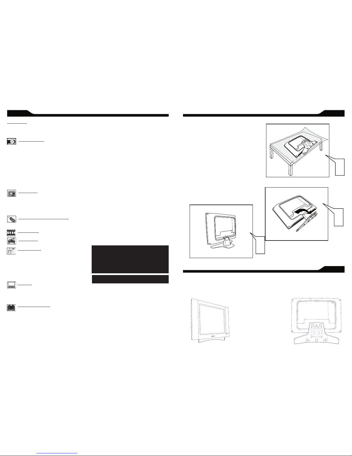
BEFORE INSTALLATION
B
efor e pro ceed to in stall your new L CD TV, pl ease
follo w the steps and diag rams as sh own t o
fami liari ze yours elf with t he corr ect a nd sa fe wa y of
unfo lding the b ase.
Place the set facing down on a fl at surface and a
protective sheet.
Unfold the base following the direction as shown on
the diagram.
Place the set upright, you LCD TV is now ready for
install.
I
NSTALLING LCD TV ON THE WALL
The stand of your LCD TV is comply with Standard VESA 75 standard, if you intend to install the LCD TV on the wall,
please consult a professional technician for proper installing.
The manufacture accepts no liability for installations not performed by professional technician.
1
2
3
75x75mm
Here are a few of the special features of your new LCD
TV.
Audio/Video In Jacks: Use to quickly connect other
equipment to your LCD TV.
Automatic Channel Programming
( Auto Program):
Quick and easy setup of available channels.
Closed Captioning: Allows the viewer to read TV
program dialog or voice conversations as on-screen text.
On-screen Menus: Helpful messages (in English, Spanish,
or French) for setting TV controls.
Remote Control: Works your LCD TV features.
Sleep Timer: Turns off the LCD TV within an amount
of time you specify (15-240 minutes from the current
time).
AutoLock: Lets you block viewing of certain TV
channels if you do not want your children viewing
inappropriate material.
Standard broadcast (VHF/UHF) or Cable TV
channel
capability
Stereo capability: Includes a built-in amplifi er and
twin-speaker system, allowing reception of TV programs
broadcast in stereo.
Treble, Bass, and Balance: Enhance the LCD TV’s
sound.
1
2
3
6
CC
SOURCE
PI P
ME NU
OK
- + - +
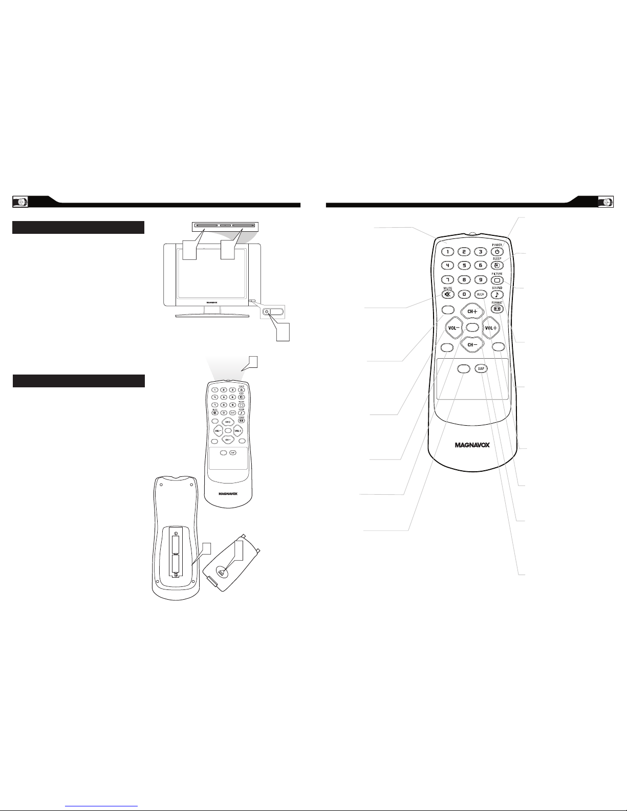
Plug the DC adapter int o the DC IN 16V jack
on the LCD T V. Plug the power cab le into an
outlet .
Press POWER to turn on the LCD TV.
Press VOLUME + to increase the sound level.
Or, press VOLUME – to lower the sound level.
Press CH+ or CH- to select channels.
Point the remote control toward on the front
of the LCD TV when
operating the LCD TV with the
remote.
Remove the battery compartment lid on the
back of the remote.
Place two AAA batteries in the
remote. Be sure the (+) and (-) ends of the
batteries line up as marked inside the battery
compartment.
Reattach the battery compartment lid.
B
ASIC TV AND REMOTE CONTROL OPERATIONS
BATTERY INSTALLATION
TELEVISION AND REMOTE CONTROL
REMOTE CONTROL
CC
SOU RCE
P IP
ME N U
OK
Number button s
Press to se lect TV ch annels.
When sele cting single-dig it
channels, press th e number of th e
desired channel.
The LCD TV will pause for a few
seconds t hen tune to the selecte d
channel.
Mute button
Press to el iminate or re store the
LCD TV soun d. Mute will appear
on the scre en when the sound is
muted.
Menu button
Press to ac tivate onscreen menu ,
back to prev ious level ins ide the
onscree n menu, also p ress to exit
the onscr een menu.
Volume button
Press to in crease or decrease the
sound level , also press to navigate
left /right in o nscreen menu.
Source butt on
Press to se lect the vid eo input
source: AV, S-Vide o, HD, PC, T V.
OK button
Press to confirm the opt ion you
select ed in the onscreen menu.
C.C button
Press the C .C butto n to select CC
on or CC off.
Standby (Power) butt on
Press to tu rn the LCD TV o n or
off.
Sleep butt on
Press to se t the LCD TV to t urn
itself off within a certain t ime.
Smart Pic ture button
Press repeatedly to select eit her
Personal, Movie, Sports, Weak
signal, or Multimedia picture
setting.
Smart Sound bu tton
Press repeatedly to select amon g
the 4 settings; Per sonal, News,
Music, or Theater.
Pictur e Format button
Press the FORMAT button
repeatedly to toggle a mong the
four scree n format size s; 4:3,
EXPAND 4 :3, COMP RESS 16:9,
or HD 4:3.
PIP button
Press repeatedly to c hange the
size of PIP w indow in PC mode.
Previous Ch annel button
Press to go t o previously selected
channel.
Channel but ton
Press to adjust the cha nnel up
or down. Al so press to sel ect or
navigate up/down in o nscreen
menu.
SAP button
Press to se lect a sound mode if
available with the T V
program ming:Mono, Stere o, or
SAP.
7
1
2
3
4
6
7
8
5
9
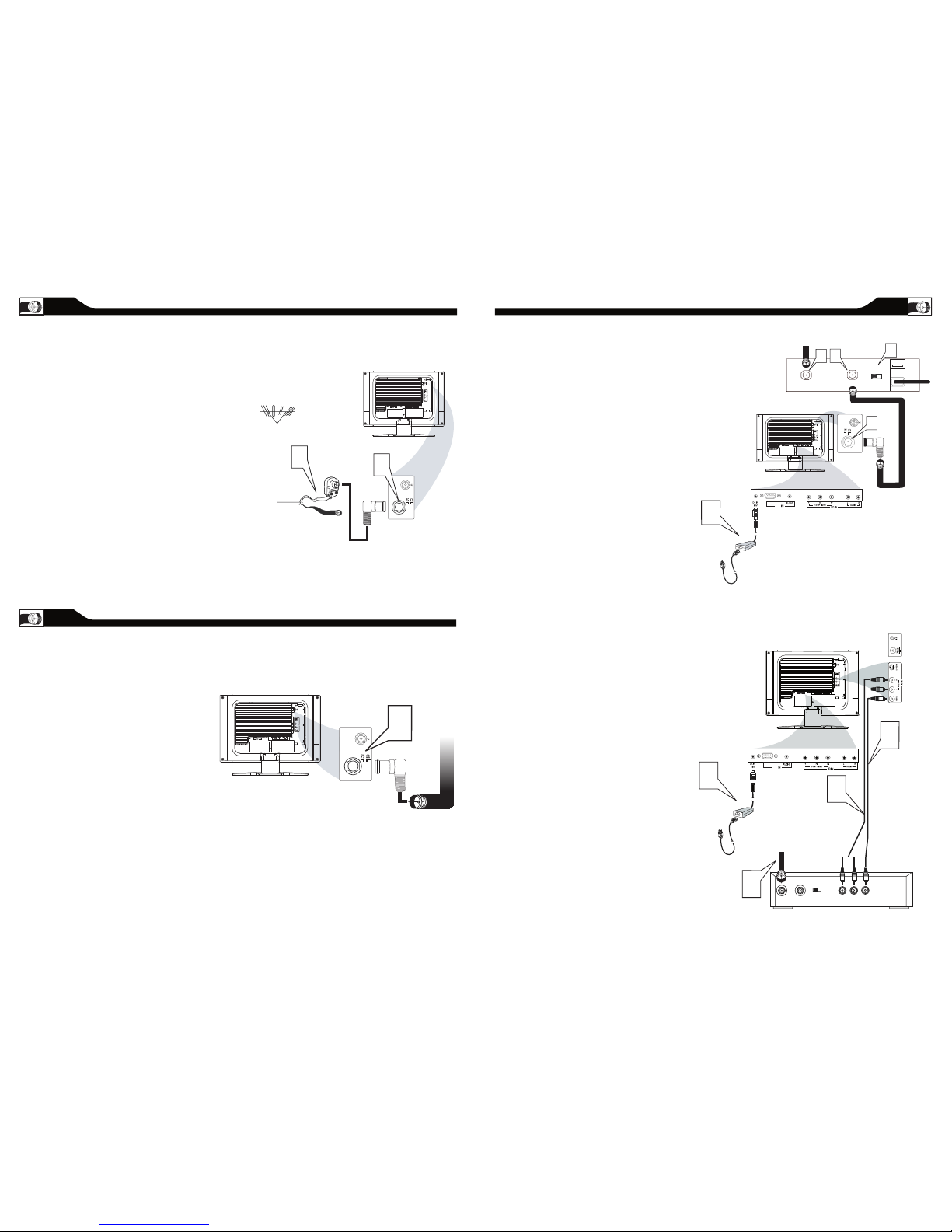
ANTENNA CONNECTION
If your antenna has a round cable
(75 ohm) on the end, then you’re ready to
connect it to the LCD TV. If your
antenna has flat, twin-lead wire (300 ohm), you
first need to attach the
antenna wires to the screws on a 300- to
75-ohm adapter(not supplied).
Connect the antenna (or adapter) to one end
of the supplied L-Adapter as shown, and con
nect the other end of the
L-Adapter to the TV jack on the side of
the LCD TV.
Connect the Cable TV signal to one end of the
supplied L-Adapter as shown, and connect the
other end of the adapter to the TV jack on the
LCD TV.
1
BASIC CABLE TV CONNECTION
2
1
Antenna
with 75
�
cable
Rear Jack panel of
Television
Outdoor or Indoor Antenna
(Combination VHF/UHF)
OR
Twin-lead
wire to
300-75
�
adapter
�
The Cable TV signal from
Cable Company
(75 coaxial cable)
Rear Jack panel of
Television
�
I
f you have a Cable Box, follow either set
of these steps to complete your
connections.
Connect the Cable T V signal to t he IN jack (or
RF IN or CABLE IN) on t he Cable Box .
Connect an RF coaxial cable (not supplied) t o
the OUT jack (or TO TV or RF OUT) of the
Cable Box .
Connect the other en d of the coax ial cable to
one end of th e supplied L-A dapter as shown,
and connect the other end of the adap ter to
the TV jack on the LCD T V.
Plug the DC adapter int o the DC IN 16V
jack on the LCD TV. Plug the power cable into
an outle t.
Set the Ch annel 3/4 ( or Output channel) sw itch
of the Cable Box to 3 or 4. Set the TV to the
same cha nnel. When watching T V
program ming, chan ge channel s at the Cable
Box, not the LCD TV.
Cable Box with Audio/Video Out Jacks
This connection will supply Stereo sound to
the LCD TV.
Connect the Cable T V signal to t he
IN jack (or R F IN or CABLE IN) on the Cable
Box.
Using an RCA -type video cable (n ot
supplie d) connect o ne end of the vid eo cable to
the Video O ut jack of the Cable Box.Co nnect
the othe r end of the cab le to the yellow VIDEO
jack on the side of the TV.Video ca bles are
usually m arked with ye llow and are avai lable
from Magn avox or electronics retailers. Video
jacks on m ost equipm ent are yellow.
Using RCA-type, s tereo audio c ables (not
supplie d), connect one end of the cables to t he
left and right Audio O ut jacks of t he Cable Box .
Connect the other en d of that cable to the
Audio jack on the side of the LCD TV.Audio
cables are usually marked with red a nd white
and are avail able from Ma gnavox or electronics
retailers.The right
audio jack is red and the left audio jac k is white.
Match the cable colors to the jack colors.
Plug the DC adapter int o the DC IN 16V
jack on the LCD TV. Plug the power cable into
an outle t.
1
2
3
4
1
2
3
5
TO TV
CABLE
IN
OUTPUT
CH
3 4
The Cable TV signal from
the Cable Compan
y
75
Coaxial
Cable
Side Jack Panel of
Television
�
DC Adapter
Power
Cable
VGA
PC
Cable Box with RF In/Out Jacks
This connection will not supply Stereo sound
to the LCD TV.
CABLE BOX CONNECTIONS
S - VIDEO
CABLE
IN
TO
TV
VIDEO
OUT
L
R
AUDIO
OUT
3 4
OUTPUT
CH
VIDEO
Cable
TV signal
Video Cable
Cable Bo
x
Audio Cable
Side Jack Panel
of
Television
AUDIO
DC Adapter
Power
Cable
VGA
PC
4
L-Adapter
L-Adapter
L-Adapter
A
combination antenna receives normal
broadcast channels (VHF 2–13 and UHF 14–69).
Your connection is easy because there is only one 75
Ω(ohm) antenna jack on the back of your TV, and that’s
where the antenna goes.
Y
our Cable TV signal into your home may be a
single, 75Ω(ohm) cable. If so, this connection is
very simple. Follow the step below to connect your
Cable TV signal to your new LCD TV.
8
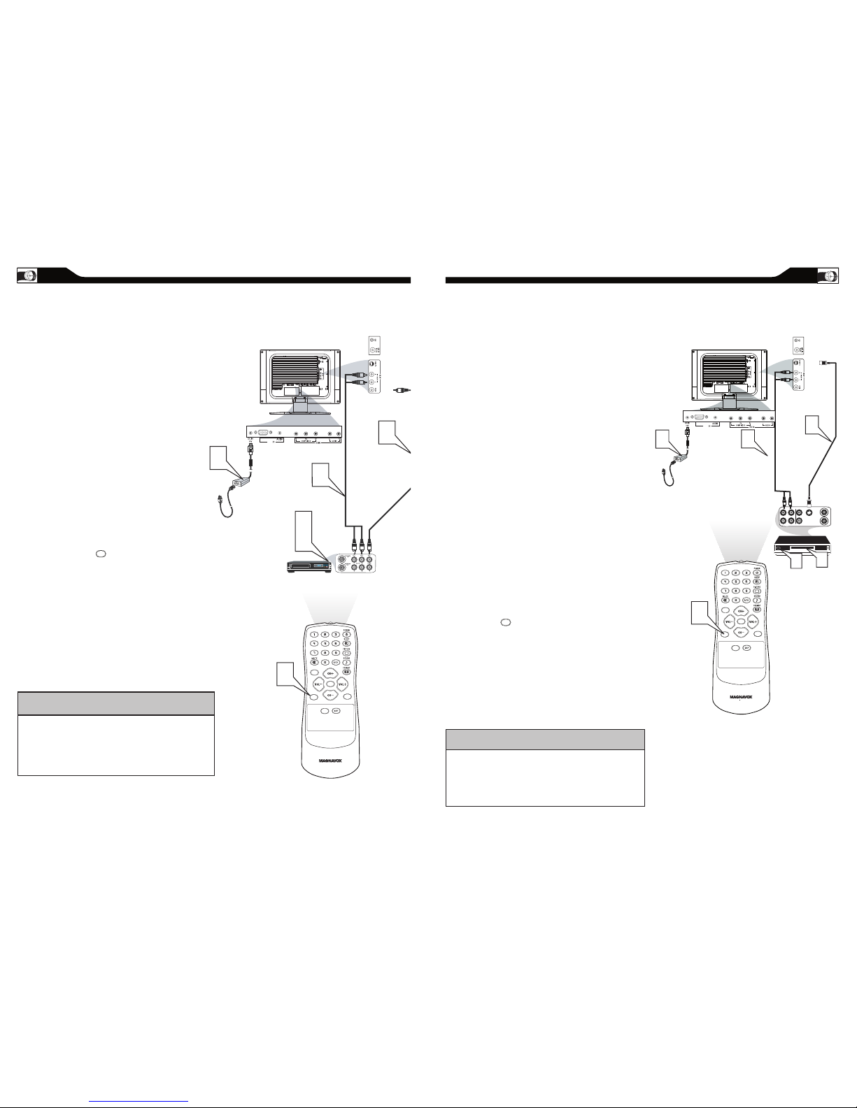
10
The Audio jack of AV IN is shared between Video
(CVBS) and S-Video signals. If Audio and Video is
connected to S-Video input, you can still hear sound if
you select Video via Source select, even there appears
no image on screen.
HELPFUL HINT
11
AUDIO/VIDEO INPUT CONNECTIONS
T
he AUD IO an d VID EO In ja cks on the
rear of th e LCD TV e nable qu ick
conn ection s of ot her equ ipme nt. C onne ct a VCR ,
DVD Pl ayer, Vide o Gam e, Ca mcor der, e tc., t o
thes e jacks. To vie w the m ateria l pla ying o n the
othe r equipm ent, se t the L CD TV to it s AV Mod e.
Connect a RCA-style video cable
(usually yellow or marked CVBS) to the
VIDEO OUT jacks of the other
equipment (DVD Player, Camcorder, etc.) and
to the yellow VIDEO jack on the side of the
LCD TV.
Connect RCA-style audio cables (usually red
and white) to the AUDIO OUT (left and right)
jacks on the other equipment. Connect the
other end of the cables to the AUDIO jack on
the side of the LCD TV.
Plug the DC Adapter into the DC IN 16V jack
on the TV. Plug the power cable into an outlet.
Turn on the TV and other equipment.
Press the Source button to set the TV to
AV Mode.
Press PLAY on the other equipment to
view its material on the TV.
1
2
3
4
5
CC
SOURCE
PI P
MEN U
OK
VIDEO
S - VIDEO
AUDIO
VGA
PC
SOURCE
S-VIDEO CONNECTIONS
T
he S-Vid eo co nnec tion on the rear of th e
LCD T V can provi de you w ith be tter
pict ure d etail and clari ty for t he pla yback o f
acc essor y sourc es such a s DBS (di gital broa dcast
sate llite) , DVD ( digit al vi deo d iscs) , vid eo gam es, and
VHS VCR (vid eo cass ette r ecorde r) tap es than the
nor mal a ntenna pictu re co nnec tion s.
Note: The accessory device must have an S-VIDEO OUT
(put) jack in order for you to complete the connection
on this page.
Connect an S-Video cable to the S -VIDEO jack of
the othe r equipment (DVD Player, Camcorder, etc.)
and to the S -VIDEO jac k on the rear of t he LCD TV.
Connect RCA-sty le audio cables (usuall y red and
white) t o the AUDIO OUT (left and right) jacks on
the othe r equipment. Connect the othe r end of the
cables t o the AUDIO jack on the side of the LCD
TV.
Plug the DC Adapter int o the DC IN 16V
jack on the LCD TV. Plug the power cable into a n
outlet . Turn on the LCD TV a nd other
equipment.
Press the S ource butt on to set
the LCD TV t o its S-VIDEO mode.
Press PL AY on the other equ ipment to
view its material on t he LCD TV.
1
2
3
4
5
CC
SOURCE
PI P
MEN U
OK
VIDEO
S - VIDEO
AUDIO
VGA
PC
SOURCE
The Audio jack of AV IN is shared
between Video (CVBS) and S-Video signals. If Audio
and Video is connected to Video (CVBS) input, you
can still hear sound if you select S-Video via Source
select, even there appears no image on screen.
HELPFUL HINT
 Loading...