

Page 1

MTT 990
BEDIENUNGSANLEITUNG
OWNER’S MANUAL
MODE D’EMPLOI
Page 2

Bitte führen Sie das Gerät am Ende seiner Lebensdauer den zur Verfügung stehenden Rückgabe- und Sammelsystemen
zu.
At the end of the product’s useful life, please dispose of it at appropriate collection points provided in your country.
Une fois le produit en fin de vie, veuillez le déposer dans un point de recyclage approprié.
Page 3
4
12
20
28
36
44
52
Page 4

Sehr geehrter MAGNAT-Kunde,
vielen Dank dafür, dass Sie sich für ein MAGNAT-Produkt entschieden haben. Wir möchten Ihnen hierzu von unserer Seite recht herzlich
gratulieren. Durch Ihre kluge Wahl sind Sie Besitzer eines Qualitätsproduktes geworden, das weltweite Anerkennung findet.
WICHTIGE SICHERHEITSHINWEISE:
Bitte lesen Sie die Bedienungsanleitung vor der Inbetriebnahme aufmerksam durch. Die Bedienungsanleitung enthält wichtige Hinweise zum
Betrieb und zur Sicherheit. Befolgen Sie unbedingt alle Hinweise. Bewahren Sie die Bedienungsanleitung gut auf.
• WARNHINWEISE: Alle Warnzeichen auf dem Gerät, dem Zubehör und in der Bedienungsanleitung müssen beachtet werden.
• WÄRMEEINWIRKUNG: Betreiben Sie das Gerät mit Zubehör nur im Temperaturbereich von 10°C bis 40°C.
Das Gerät sollen nicht in der Nähe von Wärmequellen aufgestellt werden (Heizkörper, Öfen, Heizstrahler, offene Flammen). Beim Aufstellen
in Nähe von Verstärken sollte ein Mindestabstand von 10 cm nicht unterschritten werden.
Stellen Sie keine offenen Flammen, wie z. B. Kerzen, auf das Gerät.
Achten Sie auf eine ausreichende Belüftung des Gerätes. Das Gerät darf nicht abgedeckt sein, z. B. durch Vorhänge, Gardinen. Halten Sie
ausreichend (ca. 20 cm) Abstand zu Wänden.
• EINFLUSS VON FEUCHTIGKEIT: Das Gerät darf nicht Tropf- oder Spritzwasser ausgesetzt werden. Ebenfalls darf es nicht zum Abstellen von
Vasen oder anderen mit Feuchtigkeit gefüllten Behältern benutzt werden. Setzen Sie das Gerät weder Wasser noch hoher Luftfeuchtigkeit
aus. Es besteht die Gefahr eines Stromschlags. Bei Kontakt mit Feuchtigkeit oder Flüssigkeiten trennen Sie das Gerät sofort vom Netz.
• FREMDKÖRPER: Achten Sie darauf, dass keine Fremdkörper durch die Öffnungen des Gerätes ins Innere gelangen. Sie könnten Kurzschlüs-
se auslösen und auch einen Stromschlag und Brand.
• REINIGUNG: Bitte verwenden Sie ein trockenes und weiches Tuch und keine Reinigungsmittel, Sprays oder chemische Lösungsmittel, da
sonst die Oberäche beschädigt werden könnte.
• STROMANSCHLUSS: Bitte beachten Sie die Spannungswerte auf den Hinweisschildern. Das Gerät darf nur mit den auf den Schildern ange-
gebenen Spannungswerten und Frequenzwerten betrieben werden.
• BLITZSCHUTZ/VORSICHTSMASSNAHMEN: Wird das Gerät längere Zeit (z. B. im Urlaub) nicht benutzt, sollte es durch Ziehen des Netz-
steckers vom Netz getrennt werden. Das Gerät sollte auch bei Gewitter vom Netz getrennt werden. Somit wird eine Beschädigung durch
Blitzschlag und Überspannung verhindert.
• NETZKABEL: Das Netzkabel muss immer betriebsbereit sein und sollte nur so verlegt sein, dass niemand auf das Netzkabel treten kann.
Auch darf es nicht durch Gegenstände eingeklemmt sein, die das Kabel beschädigen können. Bei Verwendung von Steckern und Mehrfachsteckdosen ist darauf zu achten, dass das Kabel an der Stelle, wo es aus der Steckdose kommt, nicht geknickt wird. Das Netzkabel nicht mit
feuchten Händen anschließen oder entfernen.
Der Netzstecker dient als Abschalteinrichtung und muss immer frei zugänglich sein.
• ÜBERLASTUNG: Steckdosen, Mehrfachsteckdosen und Verlängerungskabel sollten nicht überlastet werden. Bei Überlastung besteht Strom-
schlag- und Brandgefahr.
• AUFSTELLUNG: Bitte beachten Sie die Montageanweisung.
Das Gerät sollte nur auf festem Untergrund und nicht auf bewegliche Untergestelle gestellt oder montiert werden, da sonst Verletzungsgefahr besteht.
• Benutzen Sie nur das beigepackte oder vom Hersteller speziziertes Originalzubehör.
• Batterien und Akkus dürfen nicht großer Hitze ausgesetzt werden, wie z. B. Sonnenschein, Feuer o. ä.
Es besteht Explosionsgefahr, wenn die Batterie falsch eingesetzt wird. Ersetzen Sie die Batterie nur durch den selben oder gleichwertigen
Typ.
SCHÄDEN, DIE VOM FACHMANN BEHOBEN WERDEN MÜSSEN:
Bei den folgenden Schäden sollte das Gerät sofort vom Netz getrennt werden und ein Fachmann mit der Reparatur beauftragt werden:
• Bei sichtbaren Beschädigungen des Netzkabels darf das Gerät nicht mehr betrieben werden. Ein beschädigtes Kabel darf nicht repariert,
sondern muss ausgetauscht werden.
• Beschädigungen der Netzbuchse am Gerät.
• Wenn Feuchtigkeit oder Wasser in das Gerät gelangt ist oder Gegenstände in das Gerät gefallen sind.
• Wenn das Gerät heruntergefallen ist und das Gehäuse beschädigt ist
• Wenn das Gerät nicht richtig funktioniert, obwohl man alle Hinweise in der Bedienungsanleitung beachtet hat.
Es dürfen nur nachträgliche Änderungen vorgenommen werden, die vom Hersteller genehmigt sind.
Es dürfen zur Reparatur nur Originalersatzteile verwendet werden.
Nach einer Reparatur sollte das Gerät auf Sicherheit überprüft werden, um eine ordnungsgemäße und sichere Funktion sicherzustellen.
Reparaturen müssen immer qualizierten Fachkräften überlassen werden, da man sich sonst gefährlichen Hochspannungen oder anderen
Gefahren aussetzt.
Das Dreieck mit Blitzsymbol warnt den Benutzer, dass innerhalb des Gerätes hohe Spannungen verwendet werden, die gefährliche
Stromschläge verursachen können.
Das Dreieck mit Ausrufezeichen macht den Benutzer darauf aufmerksam, dass in der beigefügten Bedienungsanleitung wichtige
Betriebs- und Wartungsanweisungen (Reparatur) enthalten sind, die unbedingt beachtet werden müssen.
4
Page 5
Nicht öffnen! Gefahr des elektrischen Schlages!
ACHTUNG: Weder das Gehäuse/Netzteile öffnen noch Abdeckungen entfernen, um Stromschläge zu
vermeiden. Keine Reparatur durch den Benutzer. Reparatur nur durch qualizierte Techniker! Keine
Steckdosen oder Verlängerungskabel benutzen, die den Stecker des Gerätes nicht vollständig aufnehmen.
ENTSORGUNGSHINWEISE
Gemäß der europäischen Richtlinie 2012/19/EU müssen alle elektrischen und elektronischen Geräte über lokale Sammelstellen getrennt
entsorgt werden. Bitte beachten Sie die lokalen Vorschriften, und entsorgen Sie Ihre Altgeräte nicht mit dem normalen Hausmüll.
BESTIMMUNGSGEMÄSSER GEBRAUCH
Dieses Gerät ist nur für die Verwendung im Haus konzipiert.
MITGELIEFERTES ZUBEHÖR
Packen Sie das Gerät und das mitgelieferte Zubehör vorsichtig aus und überprüfen Sie den kompletten Inhalt anhand folgender Liste:
a. Plattenteller (1x)
b. Filzmatte (1x)
c. Gegengewicht (1x)
d. Systemträger (1x) (für Ausführung Art.-Nr. 149701/149701C)
e. Systemträger inkl. Tonabnehmer 1x (für Ausführung Art.-Nr. 149700/149700C)
f. Adapter für 45UPM-Schallplatten (1x)
g. Staubschutzabdeckung (1x)
h. Befestigungsgelenke für die Staubschutzabdeckung (2x)
i. Audiokabel, beidseitig Cinch-Stecker, mit Masseleitung (1x)
j. Netzkabel (1x)
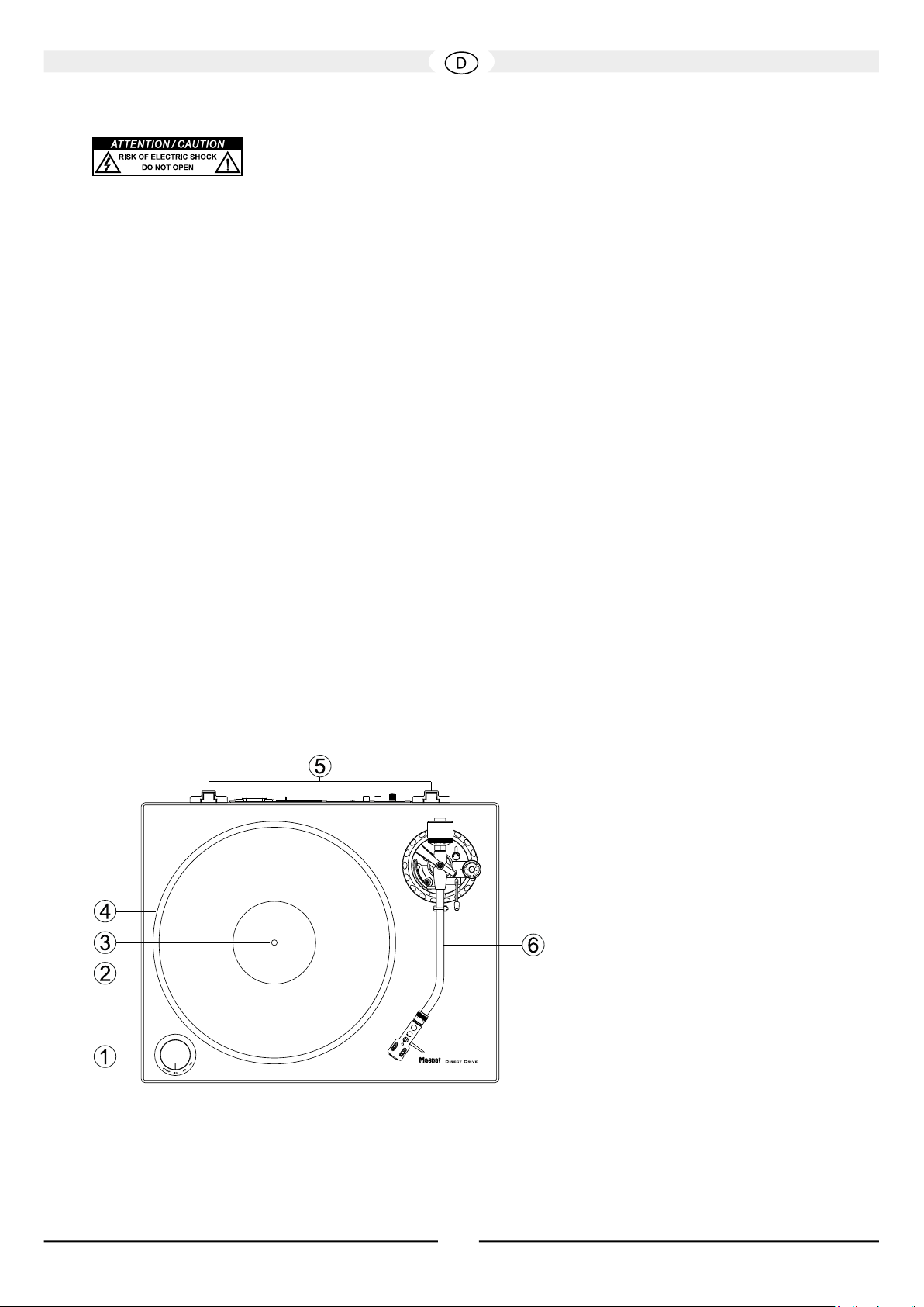
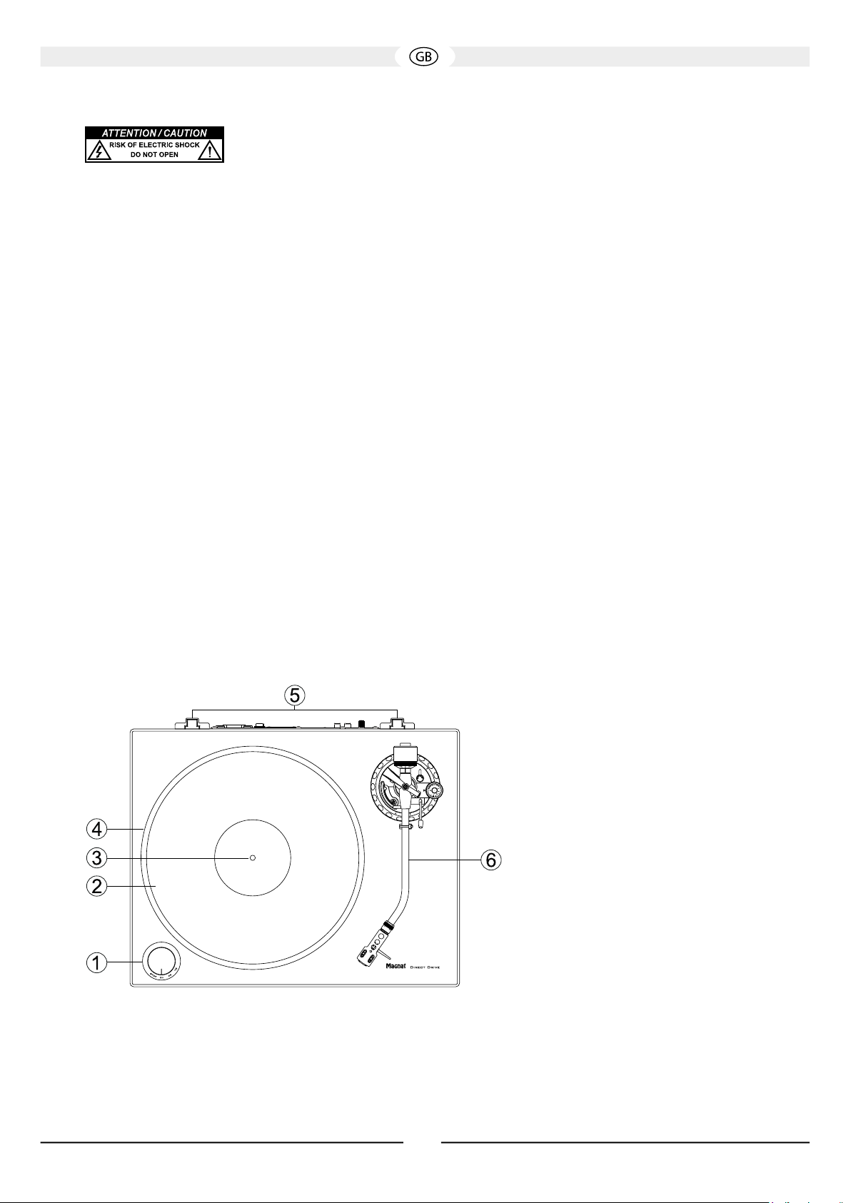
TEILE UND BEDIENELEMENTE DES GERÄTES
1) Geschwindigkeitswahlschalter
2) Plattentellerauflage (Filzmatte)
3) Motorachse
4) Plattenteller
5) Gelenkaufnahme für die Staubschutzabdeckung
6) Tonarmeinheit
Fig. 1
5
Page 6
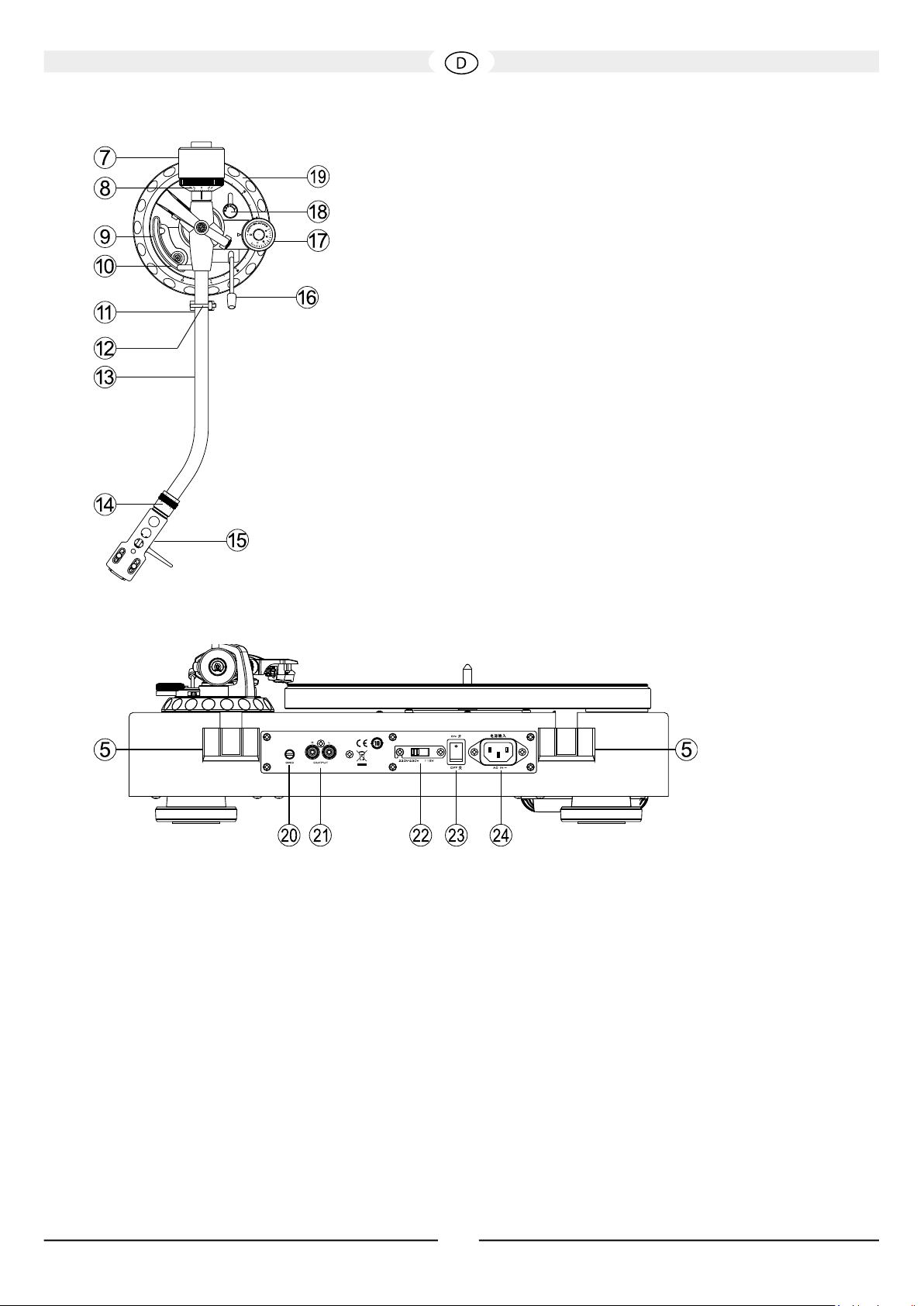
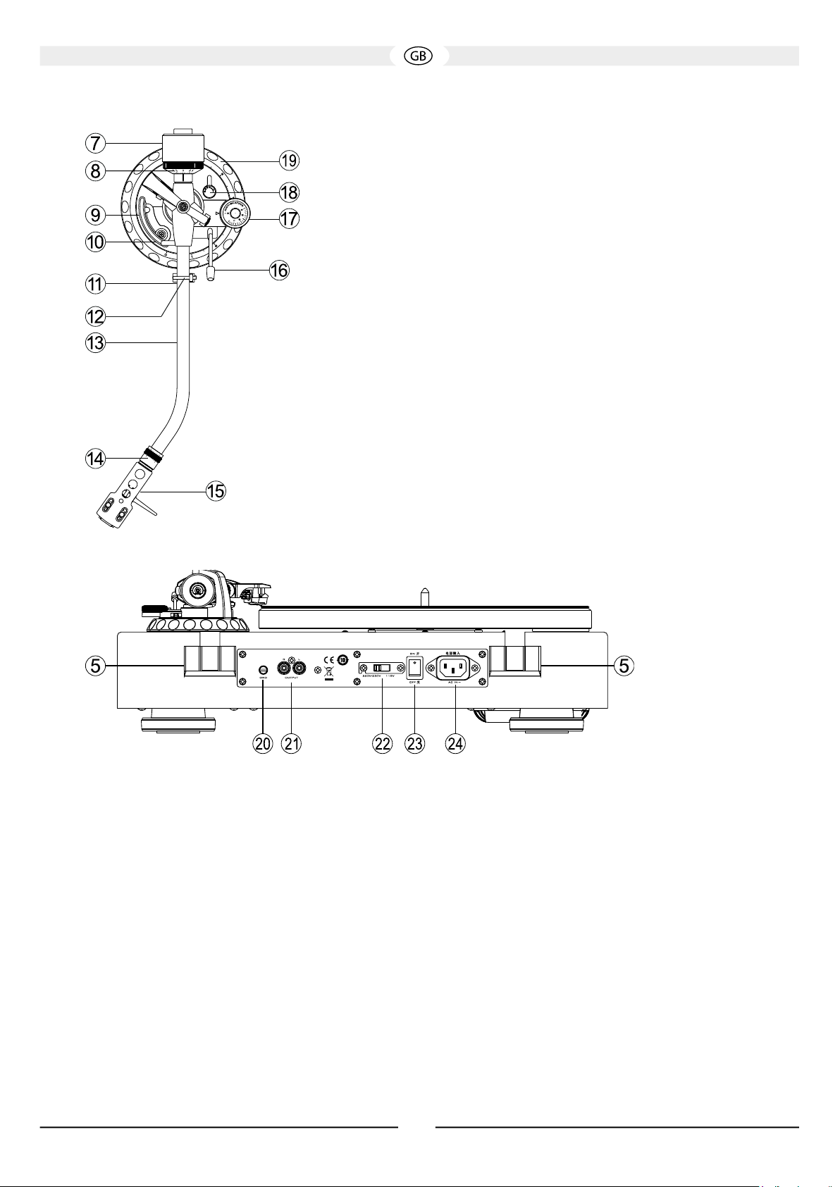
7) Gegengewicht
Fig. 3
8) Skalenring zur Einstellung der Auflagekraft
9) Tonarmheber
10) Einstellschraube zur Justierung der Lifthöhe
11) Tonarmstütze
12) Tonarmverriegelung
13) Tonarm
14) Rändermutter zur Verriegelung des Systemträgers
15) Systemträger
16) Tonarmlift
17) Drehregler zur Einstellung der Antiskating-Kraft
18) Hebel zur Verriegelung der Tonarm-Höheneinstellung
19) Einstellrad zur Tonarm-Höheneinstellung
Fig. 2
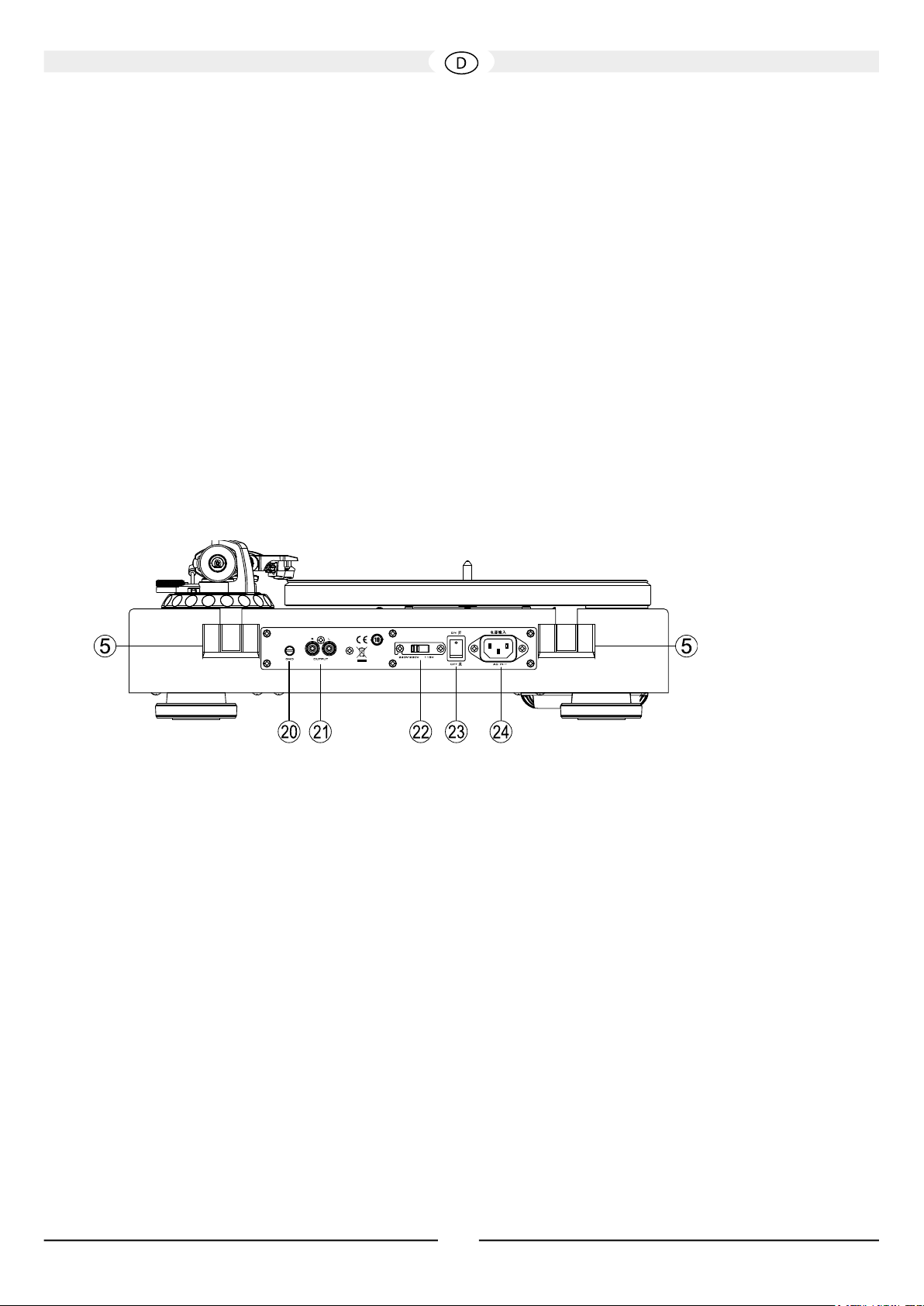
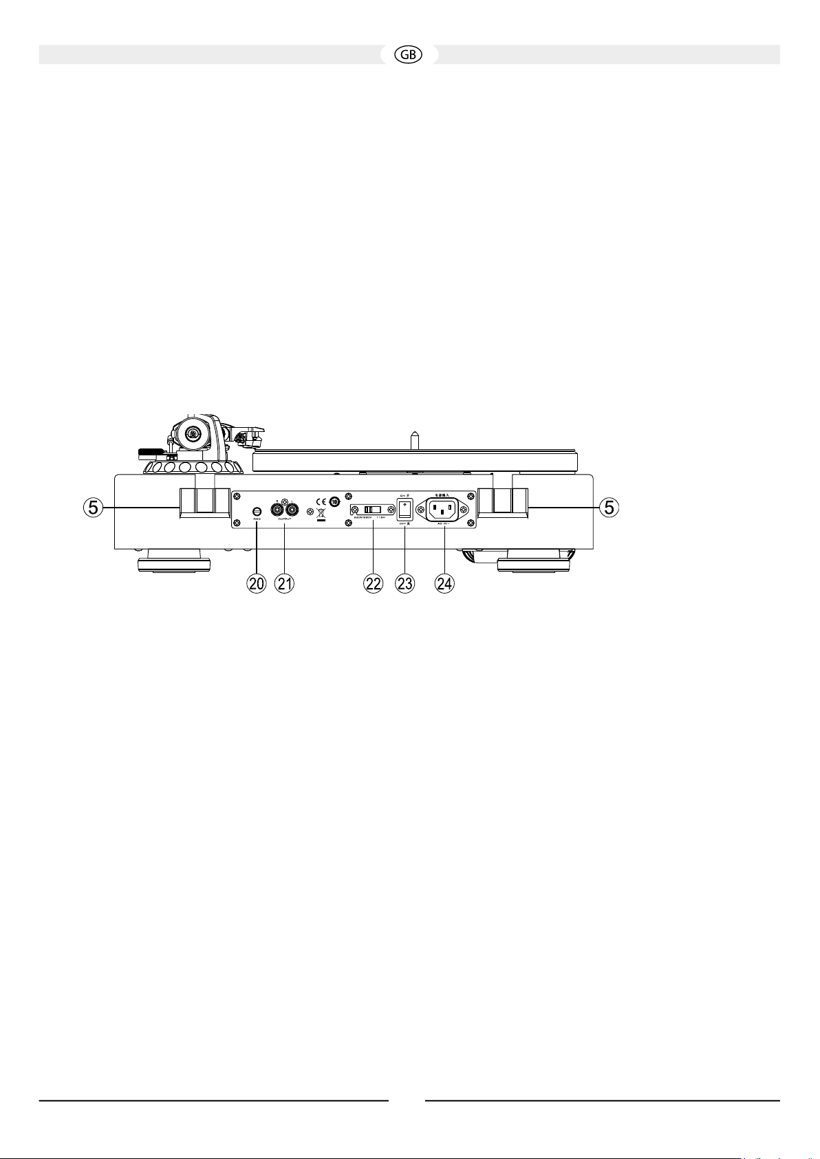
20) Klemmschraube für die Erdungsleitung
21) Audioausgänge
22) Netzspannungswahlschalter
23) Netzschalter
24) Netzbuchse
6
Page 7

ZUSAMMENBAU
Stellen Sie zunächst das Gerät auf eine saubere und stabile Oberäche.
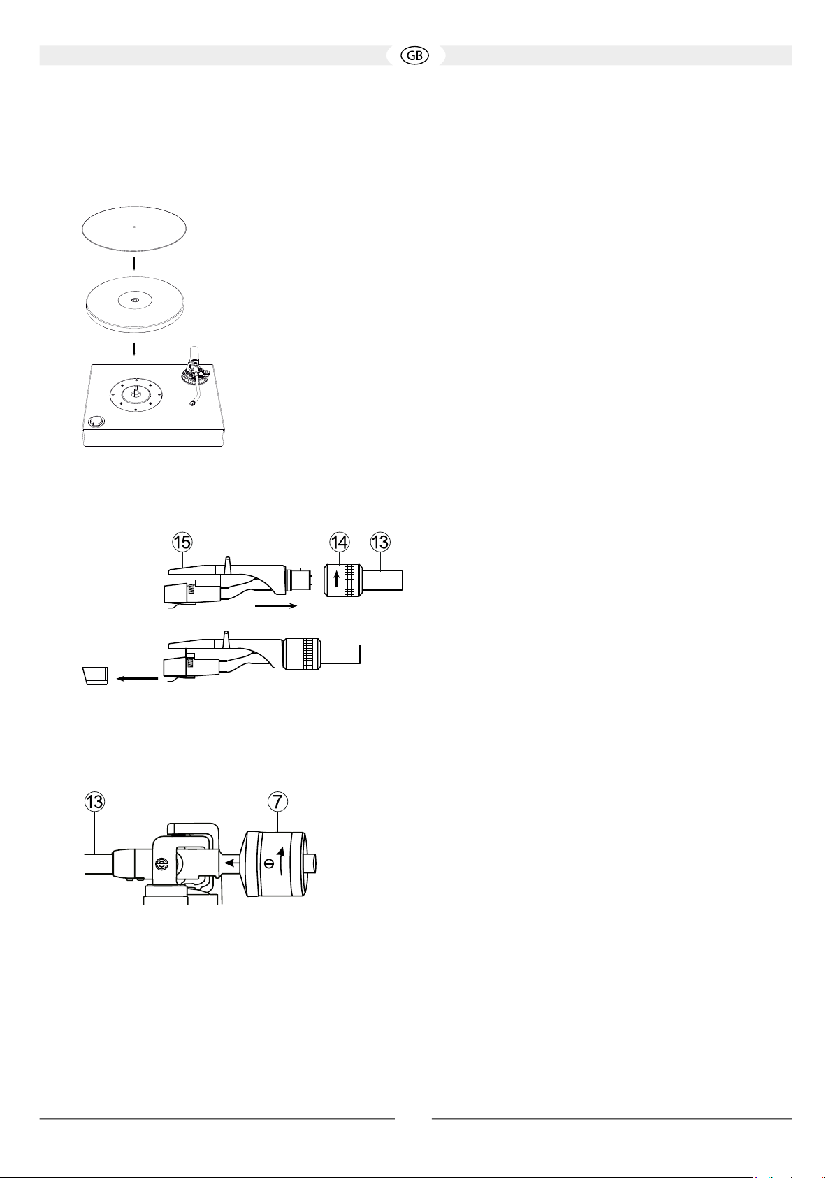
1. Montage des Plattentellers:
Setzen Sie den Plattenteller (4) mit der glatten Seite nach oben vorsichtig auf die Motorachse (3) auf. Bitte
achten Sie darauf, dass Sie bei der Montage nicht den empndlichen Tonarm beschädigen.
Zur besseren Entkopplung der Schallplatte vom Plattenteller kann die mitgelieferte Filzmatte (2) auf den
Plattenteller gelegt werden.
Fig. 4
2. Montage des Systemträgers:
Fig. 5
Fig. 6
Schieben Sie das Anschlussstück des Systemträgers (15) wie gezeigt
in das vordere Ende des Tonarms (13) und verriegeln ihn mit der
Rändelmutter (14).
Achtung: Die Ausführung Art.-Nr. 149701/149701C wird ohne
Tonabnehmersystem geliefert. Bei diesem Modell muss nun der
vorgesehene Tonabnehmer montiert werden. Bitte beachten Sie hierzu
die Montageanweisungen des Tonabnehmerherstellers.
Bei der Ausführung Art.-Nr. 149700/149700C ist ein hochwertiges
Tonabnehmersystem bereits montiert und korrekt justiert.
Das mitgelieferte Tonabnehmersystem ist mit einem Nadelschutz
ausgestattet, der für den Betrieb und für einige Einstellarbeiten
abgenommen werden muss. Bitte ziehen Sie den Nadelschutz
vorsichtig nach vorne ab (Bild 6). Wird der Plattenspieler nicht benutzt,
sollte der Nadelschutz wieder aufgesetzt werden.
3. Montage des Gegengewichtes
Montieren Sie das Gegengewicht des Tonarms (7), indem Sie es wie
gezeigt auf das hintere Ende des Tonarms aufdrehen. Drehen Sie das
Gewicht so weit nach vorne, bis die gekennzeichnete Mittellinie gerade
noch sichtbar ist.
Fig. 7
4. Waagerechtes Ausrichten des Plattenspielers
Stellen Sie das Gerät auf den vorgesehenen Platz. Die Unterlage muss stabil und eben sein, eine direkte Nähe zu Verstärker, Lautsprecher,
Rundfunkempfänger oder TV-Gerät sollte vermieden werden.
Das Gerät muss nun exakt waagerecht ausgerichtet werden. Hierzu können die vier Standfüße durch Drehen in ihrer Höhe angepasst werden.
7
Page 8
TONARMJUSTAGE
Achtung: Bei den folgenden Arbeiten bitte mit größter Sorgfalt vorgehen. Die Mechanik des Tonarms ist empfindlich, es dürfen niemals
größere Kraft oder Druck auf Teile des Tonarms ausgeübt werden.
Extreme Vorsicht ist beim Tonabnehmer und insbesondere bei der Abtastnadel geboten. Vermeiden Sie jegliche Berührung der
Abtastnadel. Beschädigte Abtastnadeln müssen sofort ausgetauscht werden, da sie die Wiedergabe verschlechtern und die Schallplatte
beschädigen können.
1. Einstellen der Tonarm-Balance
Vor dem Einstellen der Auagekraft muss zunächst die Tonarm-Balance justiert werden.
Gehen Sie hierzu wie folgt vor:
• Stellen Sie den Antiskating-Drehknopf (17) auf 0.
• Entfernen Sie den Nadelschutz des Tonabnehmersystems (Bild 6).
• Lösen Sie die Tonarmverriegelung (12), indem Sie den Verriegelungshebel nach rechts schieben.
• Justieren Sie das Tonarmgegengewicht (7) durch Drehen so, dass der Tonarm schwebt, also weder nach unten sinkt, noch nach oben steigt.
Achtung: Bitte arbeiten Sie sehr vorsichtig, damit der Tonabnehmer oder die Nadel nicht am Plattenteller oder am Gehäuse anstoßen und
beschädigt werden. Während Sie das Gegengewicht drehen, halten Sie bitte den Tonarm mit der anderen Hand fest.
2. Einstellen der Auflagekraft
Nach erfolgter Ausbalancierung des Tonarms kann nun die Auagekraft eingestellt werden.
Gehen Sie hierzu wie folgt vor:
• Drehen Sie das Skalenrad (8) am vorderen Ende des Gegengewichtes so, dass die Markierung 0 mit der Mittellinie am Tonarm uchtet.
Drehen Sie nur den Skalenring, ohne das Gegengewicht zu verstellen.
• Drehen Sie nun das Gegengewicht (7) zusammen mit dem Skalenring (8) so weit nach links, bis der gewünschte Wert der Skala (Auage-
kraft in Gramm) mit der Mittellinie uchtet.
Ausführung Art.-Nr. 149700/149700C: Empfohlene Auagekraft des mitgelieferten Tonabnehmers Audio Technica AT 95E: 2.0g
Ausführung Art.-Nr. 149701/149701C: Bitte entnehmen Sie die empfohlene Auagekraft der Produktbeschreibung des verwendeten Sys-
tems.
3. Einstellen des Antiskating
Beim Abspielen einer Schallplatte entsteht eine Kraft, die den Tonarm zum Plattenmittelpunkt zieht. Eine korrekte Antiskating-Einstellung
kompensiert diese Kraft.
Gehen Sie hierzu wie folgt vor:
• Stellen Sie die Antiskating-Kraft mit dem Drehregler (17) auf den gleichen Wert wie die Auagekraft.
4. Einstellen der Tonarmhöhe
Fig. 8
Ausführung Art.-Nr. 149700/149700C: Die Tonarmhöhe ist bereits für das vormontierte Tonabnehmersystem und für die Verwendung der
mitgelieferten Filzmatte korrekt eingestellt.
Ausführung Art.-Nr. 149701/149701C: Je nach verwendetem Tonabnehmer kann es notwendig sein, die Tonarmhöhe zu justieren. Gehen Sie
hierzu wie folgt vor:
8
Page 9
• Entriegeln Sie die Höheneinstellung, indem Sie den Lock-Hebel (18) nach links drehen.
Fig. 9
• Legen Sie eine Schallplatte auf den Plattenteller. Betätigen Sie den Tonarmlift (16) und führen Sie den Tonarm über die Platte.
• Senken Sie den Tonarmlift (16).
• Der Tonarm muss nun waagerecht und parallel zur Schallplatte ausgerichtet werden. Drehen Sie hierzu das Einstellrad an der Tonarmbasis
(19).
Achtung: Beim Einstellvorgang sollten Sie die Tonabnehmernadel mit dem Lift anheben, um Beschädigungen zu vermeiden.
• Nach korrekter Einstellung verriegeln Sie die Höheneinstellung, indem Sie den Lock-Hebel (18) nach rechts drehen.
5. Höheneinstellung des Tonarmliftes
Bei angehobenem Tonarmlift sollte sich die Nadel ca. 10-15mm über der Schallplatte benden.
Ist eine Justage notwendig, gehen Sie wie folgt vor:
• Heben Sie den Tonarmlift (16) und führen Sie den Tonarm auf die Tonarmstütze (11).
• Justieren Sie die Lifthöhe durch Drehen der Einstellschraube (10) (nach links: Lifthöhe wird größer; nach rechts: Lifthöhe wird kleiner).
Hierzu benötigen Sie einen kleinen Kreuzschlitz-Schraubendreher (nicht im Lieferumfang enthalten).
Wichtig: Beim Einstellen muss der Tonarmheber (9) nach unten gedrückt werden!
• Überprüfen Sie die Einstellung, indem Sie den Tonarm bei betätigtem Lift über die Schallplatte führen.
ANSCHLUSS UND MONTAGE DER STAUBSCHUTZABDECKUNG
1. Anschluss an den Verstärker
Schließen Sie die Audioausgänge des Plattenspielers (21) mit dem beigefügten Cinch-Audiokabel (i) an den Phono-Eingang des Verstärkers an.
Bitte achten Sie auf kanalrichtigen Anschluss: Der linke Kanal ist in der Buchse und am Stecker des Kabels weiß gekennzeichnet, der rechte
Kanal rot. Zusätzlich muss die Erdungsleitung am Plattenspieler und Verstärker angeschlossen werden. Drehen Sie hierzu die Klemmschraube
(20) auf, stecken Sie den Gabelschuh des Kabels unter die Schraube und ziehen Sie diese wieder fest.
Achtung: Verfügt Ihr Verstärker über keinen Phono-Eingang, muss ein separater Phono-Vorverstärker zwischen Plattenspieler und
Verstärker geschaltet werden.
Ausführung Art.-Nr. 149700/149700C: Für das mitgelieferte Tonabnehmersystem Audio Technica AT 95E ist ein Phono-MM (Moving Magnet)Eingang notwendig.
2. Anschluss an die Stromversorgung
Schließen Sie an die Netzbuchse (24) das beiliegende Netzkabel (j) an. Stecken Sie die andere Seite in eine Netzsteckdose.
Achtung: Der Netzspannungswahlschalter (22) ist ab Werk auf 230 V für die Verwendung im europäischen Raum eingestellt.
Wird der Plattenspieler in 115 V-Stellung an das 230 V Netz angeschlossen, führt dies zwangsläug zur Zerstörung des Gerätes!
9
Page 10
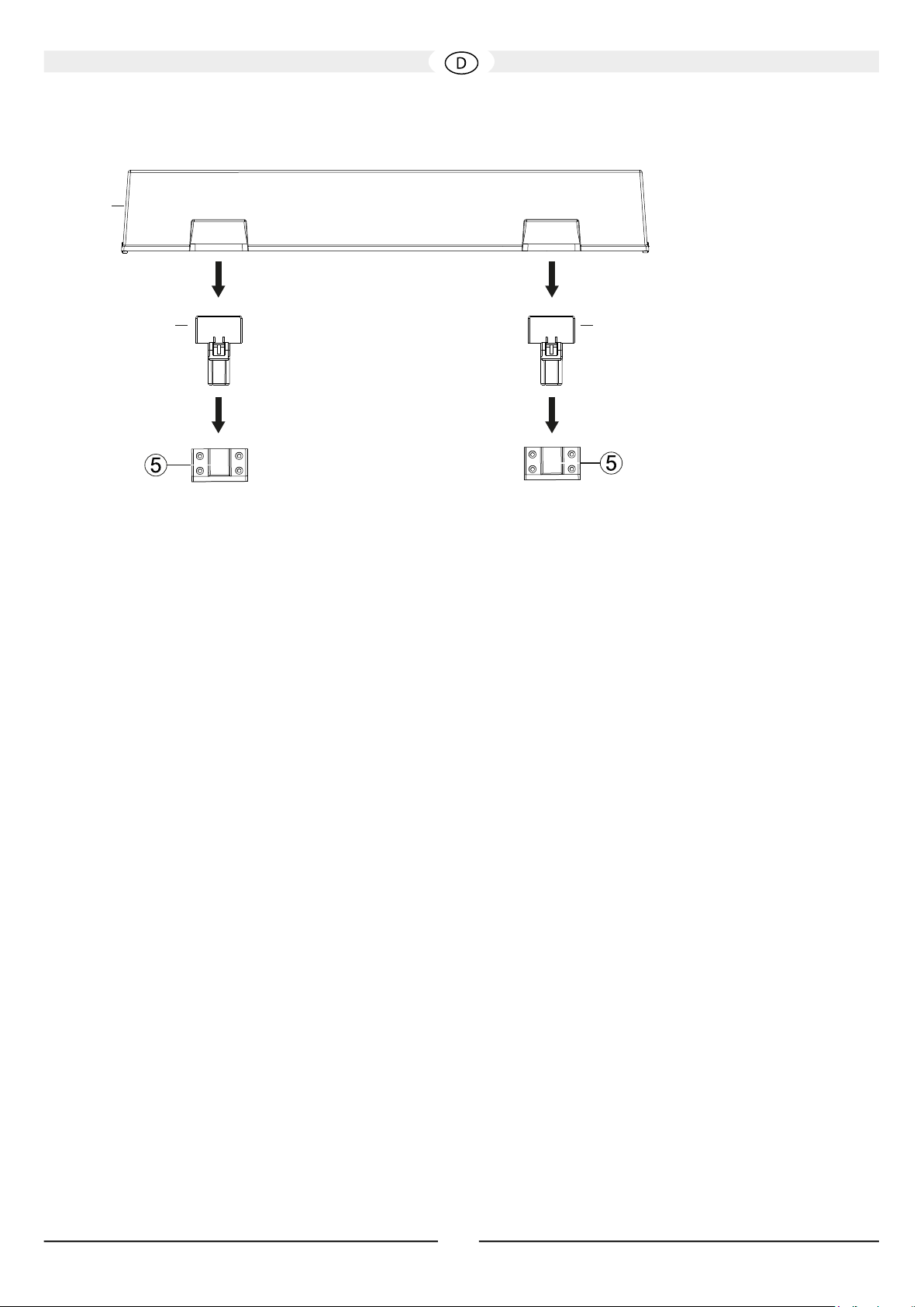
3. Montage der Staubschutzabdeckung
g
B
h h
A
Fig. 10
Nehmen Sie die beiden Befestigungsgelenke für die Staubschutzabdeckung (h) aus der Verpackung. Setzen Sie diese wie gezeigt in die
Halterungen auf der Rückseite des Gerätes ein.
Führen Sie vorsichtig die oberen achen Enden der Gelenke in die Aussparungen der Staubschutzabdeckung (g) ein.
Achtung: Bitte öffnen und schließen Sie die Abdeckung beim Abspielbetrieb (abgesenkte Nadel) sehr langsam und vorsichtig, um
Erschütterungen zu vermeiden.
BEDIENUNG
1. Abspielen einer Schallplatte
Schalten Sie das Gerät mit dem Netzschalter (23) auf der Geräterückseite ein.
Schalten Sie den angeschlossenen Verstärker ein. Wählen Sie den entsprechenden Audio-Eingang, an dem der Plattenspieler angeschlossen
ist (meist PHONO). Regeln Sie die Lautstärke am Verstärker niedrig.
Legen Sie eine Schallplatte auf den Plattenteller. Hat die Platte ein großes Mittelloch, verwenden Sie den mitgelieferten Adapter (f).
Wählen Sie die entsprechende Abspielgeschwindigkeit mit dem Geschwindigkeitswahlschalter (1) aus. Der Plattenteller dreht sich nun.
Entfernen Sie den Nadelschutz des Tonabnehmersystems (Bild 6).
Lösen Sie die Tonarmverriegelung (12), und stellen Sie den Hebel des Tonarmliftes(16) nach oben.
Führen Sie den Tonarm vorsichtig über die Einlaufrille der Schallplatte. Zur einfachen Handhabung ist rechts am Systemträger ein kleiner Griff
angebracht.
Senken Sie den Tonarm ab, indem Sie den Hebel des Tonarmliftes (16) nach unten stellen.
Regeln Sie die gewünschte Lautstärke am Verstärker.
2. Unterbrechen der Wiedergabe
Die Wiedergabe kann jederzeit durch Anheben des Tonarmliftes (16) unterbrochen werden. Der Tonarm kann dann an eine beliebige Stelle der
Platte geführt und wieder abgesenkt werden.
Achtung: Beim Betätigen des Tonarmliftes sollte die Wiedergabelautstärke reduziert werden!
3. Stoppen der Wiedergabe
Dieser Plattenspieler besitzt keine automatische Endabschaltung. Ist die Platte abgespielt und bendet sich die Abtastnadel in der Auslaufrille,
sollte der Tonarmlift möglichst umgehend betätigt werden, um einen unnötigen Verschleiß der Abtastnadel zu vermeiden.
Führen Sie dann den Tonarm zurück auf die Tonarmstütze (11), und senken Sie den Tonarmlift.
Schalten Sie den Geschwindigkeitswahlknopf (1) auf STOP.
Achtung: Wird das Gerät längere Zeit nicht benutzt, sollten Sie den Tonarm mit der Tonarmverriegelung (12) sichern.
4. Standby-Schaltung
Das Gerät verfügt über eine automatische Standby-Schaltung, die nach ca. 15 Minuten aktiviert wird (Geschwindigkeitswahlknopf in Position
STOP). In diesem Modus wird die Leistungsaufnahme des Gerätes auf unter 0,5W gesenkt. Der Standby-Modus wird deaktiviert, sobald der
Geschwindigkeitswahlknopf (1) auf eine der drei Geschwindigkeiten gestellt wird.
Achtung: Wird das Gerät längere Zeit nicht benutzt, sollten Sie den Netzschalter (23) auf der Geräterückseite auf OFF stellen.
10
Page 11

REINIGUNG UND PFLEGE
Reinigen Sie die lackierten Flächen am besten mit einem milden Haushaltsreiniger, auf keinen Fall Möbelpolitur o. ä. verwenden.
TECHNISCHE DATEN
High-End Plattenspieler mit Direktantrieb
Prinzip Quarzgesteuerter Direktantrieb
Geschwindigkeiten 33 1/3, 45, 78 rpm
Gleichlaufschwankung < 0,06 % (33 1/3 rpm)
Geräuschspannungsabstand (A) >72 dB
Fremdspannungsabstand >65 dB
Anlaufdrehmoment >2,5 kgf cm
Plattenteller Durchmesser 305 mm
Plattenteller Gewicht (ohne Auagematte) 1,9 kg
Tonarmlänge 10“
Für Tobnabnehmer mit einem Gewicht von 3 – 10 g
Für Tonabnehmer mit einer Nadelnachgiebigkeit von Mittel – hart
Überhang 16,8 mm
Kröpfungswinkel 21.4°
Gewicht Systemträger 9 g
Einstellbereich Auagekraft 0 – 35 mN / 0 – 3,5 g
Einstellbereich Antiskating Wie Auagekraft
Tonarm Höheneinstellung 6 mm
Abmessungen (BxHxT) Staubschutzabdeckung geschlossen: 450 x 162 x 365 mm
Staubschutzabdeckung geöffnet: 450 x 412 x 412 mm
Gewicht 10,7 kg
11
Page 12
Dear MAGNAT Customer,
Thank you very much for choosing MAGNAT! You have made an excellent choice. Please study the instructions and information below carefully
before using your new device.
IMPORTANT SAFETY NOTICE
Please read through the instruction manual carefully before starting to use the device. This manual contains important information concerning
operation and safety aspects. It is imperative you observe all of the information. Keep the manual in a safe location.
• WARNING NOTICES: All of the warning symbols on the device, accessories and in the instruction manual itself must be adhered to.
• EXPOSURE TO HEAT: Only operate the device and accessories in a temperature range from 10°C to 40°C.
• The device should not be positionedFet near heat sources (heaters, ovens, radiant heaters, naked ames, etc.). When setting up close to
amplier a minimum distance of 10 cm must be maintained.
No naked ame sources, such as lighted candles, should be placed on the device.
Pay attention to a sufcient ventilation of the device. The device may not be covered, e.g. by drapes, curtains. Maintain a distance of 20 cm
to walls.
• EFFECT OF MOISTURE: The device should not be exposed to dripping or splash water. Neither should it be used to support vases or other
containers lled with liquid. Do not expose the device to water or high levels of humidity. There is a danger of electric shock. In the event of
contact with moisture or liquids the device should be disconnected from the mains immediately..
• FOREIGN MATERIAL: Ensure that no foreign material enters through the device openings and into the interior. This could trigger short
circuits and even result in electric shock and re.
• CLEANING: Please use a soft, dry cloth with no cleaning agents, sprays or chemical solvents, as these could damage the surfaces.
• ELECTRICAL CONNECTION: Please note the voltage levels on the information signs. The device should only be operated with the voltage and
frequency values specied on the signs.
• LIGHTNING PROTECTION/PREVENTIVE MEASURES: If the device is not going to be used for a prolonged period (e.g. when on holiday),
it should be disconnected from the mains by removing the plug. The device should also be disconnected from the mains in the event of a
thunderstorm. Doing this will prevent damage caused by lightning and overvoltage.
• MAINS CABLE: The mains cable must always be suitable for operation and it should only ever be laid out in a manner that prevents it from
being trodden on. It should not be pinched by objects either, as this can damage the cable. When using plugs and power strips it must be
ensured that the cable is not kinked at the point where it emerges from the socket. Do not connect or remove the mains cable with damp
hands.
The mains plug is used as the disconnecting device. Disconnecting devices shall remain readily operable.
• OVERLOAD: Sockets, power strips and extension cables should not be overloaded. If an overload occurs, there is a risk of electric shock and
re.
• SETTING UP: Please read the installation instructions.
• The device should only be positioned or mounted on a solid surface and not on moving base frames, otherwise there is a risk of injury.
• Only use attachments/accessories specied by the manufacturer.
• Batteries (battery pack or batteries installed) shall not be exposed to excessive heat, such as sunshine, re and the like.
• CAUTION: Danger of explosion if battery is incorrectly replaced. Replace only with the same or equivalent type.
DAMAGE THAT MUST BE RECTIFIED BY A SPECIALIST:
If any of the following damage occurs, disconnect the device from the mains immediately and contact a specialist to conduct the repair work:
• The device should not continue to be operated if there is visible damage to the mains cable. A damaged cable should not be repaired, but
must be replaced.
• Damage to the mains socket at the device.
• If moisture or water has entered the device or foreign objects have fallen into the device.
• If the device has fallen and the housing is damaged.
• If the device does not work properly, even though all of the information in the instruction manual has been observed.
Only those subsequent alterations approved by the manufacturer may be conducted.
Only original spare parts should be used for repair.
After conducting any repairs the safety of device should be checked to ensure it is functioning correctly and safely.
Repairs must always be conducted by qualied specialists, as you might otherwise be exposed to dangerous high voltage levels or other
hazards.
The triangle with a lightning symbol warns the user that high voltage is used within the device which can result in electric shock.
The triangle with an exclamation mark informs the user that important operating and maintenance instructions (repair) are
contained in the accompanying instruction manual, which must be observed.
12
Page 13
Do not open! Risk of electric shock!
CAUTION: In order to avoid electric shock do not open the speaker housing/mains adapters or remove the
covers. The user is not to conduct any repairs him/herself. Repairs should only be conducted by qualied
technicians! Do not use any sockets or extension cables that do not fully accommodate the plug of the
device.
INSTRUCTIONS FOR DISPOSAL
In accordance with European Directive 2012/19/EU all electrical and electronic appliances must be disposed of separately via local collection
points. Please observe the local regulations and do not dispose of your old appliances with normal household waste.
USE AS DIRECTED
This device is designed for indoor use only.
INCLUDED PARTS
Please unpack the device and the accessories carefully and check if everything is complete:
a. Platter 1x
b. Felt mat for platter 1x
c. Counterweight 1x
d. Headshell 1x (for type art.no. 149 701/149 701C)
e. Headshell incl. cartridge 1x (for type art.no. 149 700/149 700C)
f. Adaptor for 45rpm records 1x
g. Dust cover 1x
h. Hinges for dust cover 2x
i. Audio cable, stereo RCA connectors at both ends, with ground line
j. Power cord
PARTS AND CONTROLS OF THE DEVICE
1) Power switch / speed selector
2) Platter mat (felt)
3) Center spindle
4) Platter
5) Brackets for dust cover hinges
6) Tone arm
Fig. 1
13
Page 14
7) Counterweight
Fig. 3
8) Stylus force adjustment dial
9) Tone arm lift
10) Tone arm lift height adjustment screw
11) Tone arm rest
12) Tone arm lock
13) Tone arm
14) Knurled nut for locking the headshell
15) Headshell
16) Cue lever
17) Anti-skate control dial
18) Tone arm height adjustment lock
19) Tone arm height adjustment dial
Fig. 2
20) Clamp screw for ground line
21) RCA stereo audio outputs
22) Mains voltage selector
23) Power switch
24) Mains connector
14
Page 15
ASSEMBLY
Make sure to place the device on a clean and sturdy surface.
1. Mounting the platter:
Carefully lower the platter (4) with the smooth side up onto the center spindle (3). Please make sure that
you do not damage the delicate tone arm.
To improve the decoupling of the record from unwanted vibration, please put the felt mat (2) onto the
platter.
Fig. 4
2. Mounting the headshell:
Fig. 5
Fig. 6
Slide the connector joint of the headshell (15) onto the front end of
the tone arm (13) and lock it by carefully turning the knurled nut
towards the platter until hand-tight.
Note: Type art.no. 149 701/149 701C comes without a cartridge.
We recommend to perform the assembly of the cartridge of your
choice at this point. Please refer to the mounting instructions given
by the cartridge manufacturer.
Type art.no. 149 700/149 700C comes with a high-quality
cartridge that has already been mounted and adjusted.
The supplied cartridge is equipped with a stylus protection cover
which has to be removed for operation and some adjustment
tasks. Please carefully pull off the protection cover to the front (g.
6). After use of the turntable, we recommend to put the protection
cover on the cartridge again.
3. Attaching the counterweight
Attach the counterweight of the tone arm (7) by screwing it onto
the rear end of the tone arm as shown. Turn the weight until the
center line on top of the tone arm is only just visible.
Fig. 7
4. Horizontal adjustment of the turntable
Place the device in its intended position. The surface must be sturdy and plane. There should be no ampliers, speakers, radios or TV sets
close to it.
Now the device needs to be accurately aligned horizontally. The height of the four feet can be adjusted by turning them.
15
Page 16
TONE ARM ADJUSTMENT
Attention: The following steps have to be carried out with utmost care. As the tone arm mechanism is very sensitive, you should never
handle any parts of the tone arm with too much force.
Please be extremely careful with the cartridge and in particular with the stylus. Avoid touching the stylus at all. Defective styluses must
be exchanged immediately as they worsen the playback quality and can damage the record.
1. Adjusting the tone arm balance
Before adjusting the stylus force, the tone arm balance needs to be adjusted.
Please proceed as follows:
• Set the anti-skate control dial (17) to 0.
• Remove the stylus cover of the cartridge (g. 6).
• Unlock the tone arm lock (12) by sliding the locking lever to the right.
• Adjust the tone arm counterweight (7) by turning it until the tone arm hovers horizontally and stops tilting upwards or downwards by itself.
Attention: Please do this very carefully and make sure that neither the cartridge nor the stylus bump into the platter or the turntable body
and get damaged. While turning the counterweight, make sure to hold the tone arm with the other hand.
2. Adjusting the stylus force
After balancing the tone arm, you should now adjust the stylus force.
Please proceed as follows:
• Turn the stylus force adjustment dial (8) at the front end of the counterweight unit its ‘0’ mark is centric with the center line of the tone arm.
Please make sure to only turn the adjustment dial itself, not the counterweight.
• Now turn the counterweight (7) together with the adjustment dial (8) towards the platter until the desired value on the dial (stylus force in
grams) matches the center line on top of the tone arm.
Type art.no. 149 700/149 700C: Recommended stylus force of the supplied cartridge Audio Technica AT 95E: 2.0g
Type art.no. 149 701/149 701C: Please check the recommended stylus force in the technical specications of the cartridge of your choice.
3. Adjusting the anti-skate
When playing a record, a force is generated that pulls the tone arm towards the center of the record. A correct anti-skate adjustment
compensates that force.
Please proceed as follows:
• Turn the anti-skate control dial (17) to the same value as the stylus force. This automatically generates the correct anti-skate value.
4. Adjusting the tone arm height
Fig. 8
Type art.no. 149 700/149 700CC: The arm height has already been adjusted correctly for the pre-assembled cartridge and the use of the
supplied felt mat.
Type art.no. 149 701/149 701C: Depending on the model of cartridge used, it might be necessary to adjust the height of the tone arm. Please
proceed as follows:
• Unlock the height adjustment by turning the lock lever (18) counter-clockwise.
• Put a record on the turntable, raise the tone arm lift with its cue lever (16) and lead the tone arm towards the record.
• Without the stylus protector in place, carefully lower the tone arm lift by pulling the cue lever downwards (16) until the stylus touches the
record.
16
Page 17
• Please carefully adjust tone arm height so that the tone arm is precisely horizontal and parallel to the record. To do this, simply turn the tone
Fig. 9
arm height adjustment dial (19) at the tone arm base.
Attention: During the adjustment, you should lift the cartridge stylus up with the tone arm lift in order to avoid damage to the stylus.
• After having completed the adjustment, lock the height adjustment by turning the lock lever (18) clockwise.
5. Adjusting the arm lift height
When the arm lift is raised, the stylus tip should be approx. 10-15mm above the record. If an adjustment is necessary, please proceed as
follows:
• Raise the tone arm lift by pushing the cue lever (16) upwards and carefully guide the tone arm onto the tone arm rest (11).
• Adjust the height of the lift by turning the adjustment screw (10) either counter-clockwise (increase lift height) or clockwise (decrease lift
height). To do this, you need a small cross-slot screwdriver (not included).
Important: During the adjustment, the tone arm lift (9) needs to be gently pushed downwards.
• Double check the adjusted height by guiding the tone arm onto the raised lift above the record.
CONNECTION AND MOUNTING OF THE DUST COVER
1. Connecting the amplifier
Please use the supplied RCA cable (i) to connect the stereo audio outputs (21) of the turntable to the input of a phono pre-amplier or a
dedicated phono input of an amplier. Please pay special attention to correct channel assignment: The left channel is marked in white (RCA
socket and RCA plug), the right channel in red. Additionally, the ground line has to be connected to the turntable and to the phono amplier. To
do this, carefully loosen the clamp screw (20), x the fork shoe of the cable under the screw and tighten it again.
Attention: If your amplier does not have a phono input, you need to use a separate phono pre-amplier between your turntable and your
amplier.
Type art.no. 149 700/149 700C: For the supplied cartridge Audio Technica AT 95E, a phono MM (Moving Magnet) input is required.
2. Connecting to the mains supply
Plug the supplied power cord (j) into the mains connector (24) and plug the other end into a power outlet.
Attention: The factory setting for the mains voltage selector (22) is 230V for use in Europe. If the turntable is set to 115V and connected
to a 230V power grid, it will inevitably be destroyed!
17
Page 18
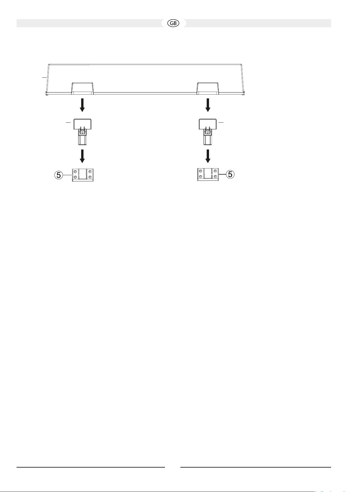
3. Mounting the dust cover
g
B
h h
A
Fig. 10
Take the hinges (h) for the dust cover out of their packaging and insert their narrow side into the slots at the rear of the turntable as shown.
Now carefully slide the dust cover (g) onto the wide side of the hinges.
Attention: Please open and close the dust cover slowly and carefully during playback (lowered stylus) in order to avoid mechanical shock.
OPERATION
1. Playing a record
Switch on the turntable by bringing the power switch (23) on the back of the turntable to the ‘ON’ position.
Power on the connected amplier and choose the input which the turntable is connected to (usually PHONO). The volume of the amplier
should be set low.
Put a record on the turntable. Use the supplied adapter (f) if the record has a large hole in the middle (f).
Choose the appropriate playback speed with the speed selector (1). The platter starts to rotate.
Remove the stylus protection from the cartridge (g. 6).
Remove the tone arm lock (12) and move the cue lever (16) upwards to raise the tone arm lift.
Carefully guide the tone arm over the lead-in groove of the record. A small handle has been mounted on the right of the headshell for easier
handling.
Lower the tone arm by moving the cue lever (16) downwards.
Adjust the desired volume on the amplier.
2. Pausing playback
The playback can be paused at any time by lifting the tone arm up with help of the arm lift (9). To do this, simply raise the cue lever (16). The
tone arm can then be guided to whatever point on the record and be put down again by lowering the cue lever (16) again.
Attention: Before raising or lowering the tone arm lift, the playback volume should be reduced!
3. Stopping playback
This turntable is not equipped with a limit stop. When the record is played and the stylus entered the lead-out groove, the tone arm lift should
soon be raised manually in order to avoid unnecessary wear of the stylus.
Carefully put the tone arm back onto the tone arm rest (11) and lower the arm lift (9) with the cue lever (16).
Turn the speed selector (1) to the ‘STOP’ position.
Attention: If the device is not used for a prolonged period of time, the tone arm should be secured with the tone arm lock (12).
4. Standby mode
This device is provided with an automatic standby mode which is automatically activated after 15 minutes of non-use (speed adjustment
dial set to ‘STOP’). In standby mode, the power consumption of the turntable is reduced to less than 0.5 W to avoid unnecessary power
consumption. The standby mode will be interrupted automatically as soon as the speed selector (1) is set to one of the three speeds.
If the device is not used for a prolonged period of time, the power switch (23) on the back of the device should be set to the ‘OFF’ position.
18
Page 19

CLEANING AND CARE
The lacquered surface is best cleaned with a mild household cleaner. On no account use furniture polish or similar products on these
surfaces.
TECHNIAL SPECIFICATIONS
High end direct drive turntable
Speeds 33 1/3, 45, 78 rpm
Wow & utter < 0.06% (33 1/3 rpm)
Signal/noise ratio (A-weighted) > 72 dB
Signal/noise ratio (unweighted) > 65 dB
Torque > 2.5 kgf cm
Platter diameter 305 mm
Platter weight (net) 1.9 kg
Tonearm length 10“
For cartridges weighing 3 – 10 g
For cartridges with a dynamic compliance of Medium – medium-stiff
Overhang 16.8 mm
Offset angle 21.4°
Weight of headshell 9 g
Adjustment range of tracking force 0 – 35 mN / 0 – 3.5 g
Adjustment range of antiscating Analogue to tracking force
VTA (height adjustment) 6 mm
Cabinet surface Piano Schwarz / piano black
Dimensions (wxhxd)
Cover closed: 450 x 162 x 365 mm
Cover open: 450 x 412 x 412 mm
Weight 10.7 kg
19
Page 20

Très cher client,
Félicitations: vous venez d’acquérir de nouvelles enceintes d’excellente qualité et nous vous remercions d’avoir choisi MAGNAT! Votre
choix est excellent: les appareils MAGNAT ont en effet d’une réputation mondiale. Veuillez lire attentivement la notice d’utilisation avant
la mise en marche de l’appareil.
AVIS IMPORTANT DE SÉCURITÉ
Veuillez lire attentivement la notice d’utilisation avant la mise en marche de l’appareil. La notice d’utilisation comporte des consignes
de fonctionnement et de sécurité importantes. Respectez impérativement toutes les consignes. Conservez soigneusement la notice
d’utilisation.
• AVERTISSEMENTS : Impérativement respecter tous les symboles d’avertissement sur l’appareil, les accessoires et dans la notice
d’utilisation.
• EFFET DE LA CHALEUR : Utilisez uniquement l’appareil à une température comprise entre 10 et 40 °C.
Ne pas installer l’appareil à proximité de sources de chaleur (radiateurs, poêles, radiateurs infrarouges, ammes nues). En cas
d’installation à proximité d’amplicateurs, observez une distance minimale de 10 cm
• Tenez l‘appareil éloigné des ammes nues, des bougies par exemple.
• Veillez à une aération sufsante de l’appareil. Il est interdit de recouvrir l’appareil, par ex. avec des rideaux ou stores. Observez une
distance sufsante (env. 20 cm) par rapport aux murs.
• INFLUENCE DE L’HUMIDITÉ : L’appareil ne doit pas être exposé à des gouttes ou projections d’eau. De même, il ne doit pas être utilisé
comme support pour des vases ou des récipients contenant un liquide. N’exposez l’appareil ni à l’eau ni à une humidité importante de
l’air. Cela risquerait d’entraîner une décharge électrique. En cas de contact avec des objets humides ou des liquides, mettez-le sous
tension en débranchant le cordon d’alimentation
• CORPS ÉTRANGERS : Veillez à ce qu’aucun corps étranger ne pénètre à l’intérieur de l’appareil à travers les orices. Leur présence
risquerait de provoquer des courts-circuits mais également une décharge électrique ou un incendie.
• NETTOYAGE : Veuillez employer un chiffon sec et doux et évitez d’appliquer tout produit de nettoyage, spray ou solvant chimique an de
ne pas endommager la surface de l’appareil.
• RACCORDEMENT ÉLECTRIQUE : Veuillez respecter les valeurs de tension indiquées sur les étiquettes. L’appareil doit uniquement
fonctionner avec les tensions et fréquences indiquées sur les étiquettes.
• PROTECTION CONTRE LA FOUDRE / MESURES DE PRÉCAUTION : Si l’appareil n’est pas utilisé pendant une période prolongée (par ex.
en vacances), mettez-le sous tension en débranchant le cordon d’alimentation. En cas d’orage, l’appareil doit également être mis sous
tension an d’éviter tout risque d’endommagement dû à un coup de foudre ou à une surtension.
• CORDON D’ALIMENTATION : Le cordon d’alimentation doit toujours être en état de fonctionner et posé de manière à ce que personne
ne puisse marcher dessus. Pour éviter tout risque d’endommagement du cordon, veiller à ce qu’il ne soit coincé par aucun objet. En cas
d’utilisation de ches et de prises multiples, veillez à ce que le cordon ne soit pas plié à l’endroit où il sort de la prise. Ne pas toucher le
câble d‘alimentation avec des mains mouillées.
• La prise secteur permet d‘arrêter l‘appareil et doit donc toujours être facilement accessible.
• SURCHARGE : Les prises, prises multiples et rallonges ne devraient pas être surchargées. En cas de surcharge, il y a danger
d’électrocution et d’incendie.
• MONTAGE : Veuillez observer les instructions de montage.
L’appareil devrait uniquement être posé ou monté sur un support xe et non pas sur des châssis mobiles an d’éviter tout risque de
blessure.
• Utilisez uniquement les accessoires d’origine fournis ou agréés par le fabricant.
• Les batteries et les piles ne doivent pas être exposées à des chaleurs importantes, comme celle générées par le soleil ou le feu.
• Risque d’explosion en cas de mauvaise installation de la batterie. Remplacez la batterie uniquement par une batterie du même type ou
similaire.
DOMMAGES DEVANT ÊTRE RÉPARÉS PAR UN SPÉCIALISTE :
En présence d’un ou plusieurs des dommages mentionnés ci-dessous, mettez immédiatement l‘appareil sous tension et conez la
réparation à un spécialiste :
• En cas d’endommagement visible du cordon d’alimentation, l’appareil ne doit plus être utilisé. Tout cordon d’alimentation endommagé ne
doit pas être réparé mais remplacé.
• Détériorations de la prise secteur sur l’appareil.
• Présence d’humidité ou d’eau dans l’appareil ou chute d’objets dans l’appareil.
• Chute de l‘appareil et endommagement du boîtier.
• Dysfonctionnement de l’appareil bien que toutes les consignes gurant dans la notice d‘utilisation aient été respectées.
N’effectuez des interventions ultérieures sur l’appareil que si celles-ci sont autorisées par le fabricant.
Ne procédez à des réparations qu’avec des pièces d’origine.
Suite à une réparation, vériez que l‘appareil est conforme aux normes de sécurité an de garantir un fonctionnement correct et sûr.
Conez systématiquement toute réparation à un personnel qualié sous peine de vous exposer à des risques de haute tension ou à d’autres
dangers.
20
Page 21

Le triangle comportant le symbole d‘un éclair avertit l’utilisateur que l’appareil est traversé par des tensions élevées pouvant
entraîner des décharges électriques dangereuses.
Le triangle comportant le point d‘exclamation indique à l’utilisateur de l’appareil que la notice d’utilisation jointe avec l’appareil
contient des consignes d’utilisation et d’entretien importantes devant impérativement être respectées.
Attention! Ne pas ouvrir, risque d‘électrocution!
RISK OF ELECTRIC SHOCK
DO NOT OPEN
ATTENTION : Veillez à ne pas ouvrir le boîtier/les blocs d’alimentation du haut-parleur ni à retirer les caches
de protection an d‘éviter tout risque de décharge électrique. Aucune réparation ne doit être effectuée par
l’utilisateur de l’appareil. Toute réparation doit être conée exclusivement à un personnel qualié ! N‘utilisez ni
prises ni rallonges dans lesquelles il n’est pas possible d‘enfoncer complètement le connecteur.
INSTRUCTIONS POUR LA MISE EN REBUT
Conformément à la directive européenne 2012/19/EU, tous les appareils électriques et électroniques usagés doivent être triés et déposés
dans des points de collecte locaux. Veuillez respecter les réglementations locales et ne pas jeter vos appareils usagés avec les déchets
ménagers.
UTILISATION CONFORME
Cet appareil a exclusivement été conçu pour une utilisation dans la maison.
ACCESSOIRES FOURNIS
Déballez soigneusement l’appareil et les accessoires fournis, puis vériez le contenu complet à l’aide de la liste suivante :
a. Plateau tournant (1x)
b. Feutrine (1x)
c. Contrepoids (1x)
d. Porte-cellule (1x) (pour version réf. 149701/149701C)
e. Porte-cellule incl. cellule 1x (pour version réf. 149700/149700C)
f. Adaptateur pour disques 45 tours (1x)
g. Capot anti-poussière (1x)
h. Charnières de fixation pour capot anti-poussière (2x)
i. Câble audio, connecteurs RCA-RCA, avec fil de masse (1x)
j. Câble électrique (1x)
PIÈCES ET ÉLÉMENTS DE COMMANDE DE L’APPAREIL
1) Sélecteur de vitesse
2) Support vinyle (feutrine)
3) Axe moteur
4) Plateau tournant
5) Supports de xation pour capot anti-poussière
6) Bras de lecture
21
Fig. 1
Page 22

7) Contrepoids
Fig. 3
8) Bague graduée pour le réglage de la force d’appui
9) Levier de bras de lecture
10) Vis de réglage pour ajustement de la hauteur de levage
11) Support de bras de lecture
12) Verrou de bras de lecture
13) Bras de lecture
14) Écrou moleté pour verrouillage du porte-cellule
15) Porte-cellule
16) Poignée de bras de lecture
17) Bouton de réglage de la force anti-patinage
18) Levier pour verrouillage du réglage de hauteur du bras de lecture
19) Cadran pour réglage de la hauteur du bras de lecture
Fig. 2
20) Vis de serrage pour le câble de mise à la terre
21) Sorties audio
22) Sélecteur de tension secteur
23) Interrupteur d’alimentation
24) Prise d’alimentation
22
Page 23

CONSTRUCTION
Placez d’abord l’appareil sur une surface propre et stable.
1. Montage du plateau tournant :
Posez prudemment le plateau tournant (4) sur l’axe moteur (3) avec le côté lisse vers le haut. Veillez à ne
pas endommager le bras de lecture sensible pendant le montage.
Pour un meilleur découplage du disque sur le plateau tournant, il est possible de placer la feutrine (2)
fournie sur le plateau tournant.
Fig. 4
2. Montage du porte-cellule :
Glissez le connecteur du porte-cellule (15) comme présenté dans
l’extrémité avant du bras de lecture (13) et le verrouiller avec l’écrou
moleté (14).
Attention : La version réf. 149701/149701C est livrée sans système
de cellule. Ce modèle nécessite maintenant le montage de la cellule
souhaitée. Respectez pour cela les instructions de montage du
fabricant de la cellule.
Fig. 5
Pour la version réf. 149700/149700C, un système de cellule de haute
qualité est déjà monté et correctement ajusté.
Le système de cellule fourni est équipé d’un protège-diamant qui doit
être retiré pour le fonctionnement et pour certains travaux de réglage.
Tirez avec précaution le protège-diamant vers l’avant (illustration 6).
Fig. 6
Le protège-diamant doit être remis en place quand la platine n’est pas
utilisée.
3. Montage du contrepoids
Montez le contrepoids (7) du bras de lecture en le tournant sur
l’extrémité arrière du bras de lecture comme présenté. Vissez le poids
vers l’avant jusqu’à ce que la ligne centrale marquée soit à peine
visible.
Fig. 7
4. Alignement horizontal de la platine
Posez l’appareil à l‘emplacement souhaité. La base doit être stable et plane ; la proximité directe d’un amplicateur, de haut-parleurs, d’un
récepteur radio ou d’un téléviseur doit être évitée.
L’appareil doit maintenant être aligné exactement à l’horizontale. Pour cela, il est possible d’ajuster la hauteur des quatre pieds en les
tournant.
23
Page 24

AJUSTAGE DU BRAS DE LECTURE
Attention : Veuillez procéder avec le plus grand soin pour les travaux suivants. Le mécanisme du bras de lecture est sensible. N’exercez
jamais de grande force ou pression sur les pièces du bras de lecture.
Des précautions extrêmes doivent être prises avec la cellule et surtout avec le diamant. Évitez tout contact avec le diamant. Les diamants
endommagés doivent être remplacés immédiatement car ils peuvent détériorer la lecture et endommager le disque.
1. Réglage de la balance du bras de lecture
Avant de régler la force d’appui, il faut d’abord ajuster la balance du bras de lecture.
Pour cela, veuillez suivre les étapes suivantes :
• Réglez le bouton anti-patinage (17) sur 0.
• Retirez le protège-diamant du système de cellule (illustration 6).
• Débloquez le verrou de bras de lecture (12) en poussant le levier de verrouillage vers la droite.
• Ajustez le contrepoids (7) du bras de lecture en le tournant, de sorte que le bras de lecture soit en équilibre, sans qu’il ne s’abaisse ni se
relève.
Attention : Veuillez procéder avec une grande précaution pour éviter que la cellule ou le diamant ne cognent contre le plateau tournant ou
le boîtier et ne soient endommagés. Pendant que vous tournez le contrepoids, tenez bien le bras de lecture avec l’autre main.
2. Réglage de la force d’appui
Une fois que le bras de lecture a été correctement équilibré, la force d’appui peut maintenant être réglée.
Pour cela, veuillez suivre les étapes suivantes :
• Tournez la bague graduée (8) à l’extrémité avant du contrepoids de sorte que la marque 0 soit alignée avec la ligne centrale du bras de
lecture. Tournez maintenant la bague graduée sans dérégler le contrepoids.
• Tournez maintenant le contrepoids (7) et la bague graduée (8) aussi loin que possible vers la gauche, jusqu’à ce que la valeur souhaitée de
l’échelle (force d’appui en gramme) soit alignée avec la ligne centrale.
Version réf. 149700/149700C : force d’appui conseillée de la cellule fournie Audio Technica AT 95E : 2,0g
Version réf. 149701/149701C : veuillez consulter la description du produit utilisé pour connaître la force d’appui recommandée.
3. Réglage de l’anti-patinage
Lors de la lecture d’un disque, une force est générée qui tire le bras de lecture vers le centre du disque. Un réglage correct de l’anti-patinage
compense cette force.
Pour cela, veuillez suivre les étapes suivantes :
• Utilisez le bouton de réglage (17) pour régler la force d’anti-patinage à la même valeur que la force d’appui.
4. Réglage de la hauteur du bras de lecture
Fig. 8
Version réf. 149700/149700C : la hauteur du bras de lecture est déjà correctement réglée pour le système de cellule pré-installé et pour
l’utilisation avec la feutrine fournie.
Version réf. 149701/149701C : selon la cellule utilisée, il peut être nécessaire d’ajuster la hauteur du bras de lecture. Pour cela, veuillez
suivre les étapes suivantes :
24
Page 25

• Déverrouillez le réglage de hauteur en tournant le levier de verrouillage (18) vers la gauche.
Fig. 9
• Placez un disque sur le plateau tournant. Levez la poignée de bras de lecture (16) et guidez le bras de lecture sur le disque.
• Baissez la poignée de bras de lecture (16).
• Le bras de lecture doit maintenant être aligné horizontalement et parallèle au disque. Pour cela, tournez le cadran de réglage (19) à la base
du bras de lecture.
Attention : Lors du processus de réglage, levez le diamant de la cellule avec la poignée an d’éviter les dégâts.
• Après le réglage correct, verrouillez le réglage de hauteur en tournant le levier de verrouillage (18) vers la droite.
5. Réglage en hauteur de la poignée de bras de lecture
Quand la poignée de bras de lecture est levée, le diamant devrait être à env. 10-15 mm au-dessus du disque.
Si un ajustage est requis, procédez de la manière suivante :
• Levez la poignée de bras de lecture (16) et guidez le bras de lecture sur le support de bras de lecture (11).
• Ajustez la hauteur de levage en tournant la vis de réglage (10) (vers la gauche : la hauteur de levage augmente ; vers la droite : la hauteur
de levage diminue). Vous avez besoin pour cela d’un petit tournevis cruciforme (non fourni).
Important : Le levier de bras de lecture (9) doit être abaissé pendant le réglage !
• Vériez le réglage en déplaçant le bras de lecture sur le disque lorsque la poignée est levée.
BRANCHEMENT ET MONTAGE DU CAPOT ANTI-POUSSIÈRE
1. Branchement à l’amplificateur
Branchez les sorties audio de la platine (21) à l’entrée phono de l’amplicateur à l’aide du câble audio RCA fourni (i). Respectez les canaux :
le canal de gauche est marqué en blanc (prise et connecteur), le canal de droite est marqué en rouge. De plus, le câble de mise à la terre doit
être connecté à la platine et à l’amplicateur. Pour ce faire, ouvrez la vis de serrage (20), insérez la cosse fourche du câble sous la vis puis
resserrez-la.
Attention : Si votre amplicateur ne dispose pas d’entrée Phono, un préamplicateur Phono séparé doit être branché entre la platine et
l’amplicateur.
Version réf. 149700/149700C : le système de cellule fourni Audio Technica AT 95E nécessite une entrée Phono MM (Moving Magnet).
2. Branchement électrique
Branchez le câble électrique fourni (j) à la prise d’alimentation (24). Branchez l’autre extrémité dans une prise électrique.
Attention : Le sélecteur de tension secteur (22) est réglé par défaut sur 230 V pour l’utilisation dans l’espace européen.
Si la platine est réglée sur 115 V et branchée sur du 230 V, cela détériorera inévitablement l’appareil !
25
Page 26

3. Montage du capot anti-poussière
g
B
h h
A
Fig. 10
Sortez les deux charnières de xation (h) du capot anti-poussière de l’emballage. Placez-les dans les supports à l’arrière de l’appareil comme
présenté.
Insérez avec précaution les extrémités supérieures plates des charnières dans les ouvertures du capot anti-poussière (g).
Attention : Veuillez ouvrir et fermer le capot lentement et avec précaution durant la lecture (diamant abaissé) an d’éviter les
soubresauts.
UTILISATION
1. Lecture d’un disque
Allumez l’appareil à l’aide de l’interrupteur d’alimentation (23) situé à l’arrière de l’appareil.
Allumez l’amplicateur branché. Sélectionnez l’entrée audio correspondante où la platine est branchée (généralement PHONO). Réglez un
volume bas sur l’amplicateur.
Placez un disque sur le plateau tournant. Si le disque a un gros trou central, utilisez l’adaptateur fourni (f).
Utilisez le sélecteur de vitesse (1) pour sélectionner la vitesse de lecture appropriée. Le plateau tournant se met à tourner.
Retirez le protège-diamant du système de cellule (illustration 6).
Débloquez le verrou de bras de lecture (12) et levez la poignée de bras de lecture (16).
Guidez avec précaution le bras de lecture sur la rainure de départ du disque. Une petite anse est xée sur le côté droit du porte-cellule pour
faciliter la manipulation.
Abaissez le bras de lecture en abaissant la poignée du bras de lecture (16).
Réglez le volume voulu sur l’amplicateur.
2. Suspendre la lecture
La lecture peut être suspendue à tout moment en levant la poignée du bras de lecture (16). Le bras de lecture peut ensuite être déplacé à
n’importe quelle position sur le disque puis à nouveau abaissé.
Attention : Il faut baisser le volume de diffusion avant d’actionner la poignée du bras de lecture !
3. Stopper la lecture
Cette platine ne dispose pas d’arrêt nal automatique. Une fois que le disque est terminé et que le diamant se trouve dans la rainure de n, la
poignée de bras de lecture doit être levée dès que possible an d’éviter une usure inutile du diamant.
Remettez ensuite le bras de lecture sur le support de bras de lecture (11), et abaissez la poignée de bras de lecture.
Mettez le sélecteur de vitesse (1) sur STOP.
Attention : Si l’appareil n’est pas utilisé pendant une longue période, vous devez fixer le bras de lecture avec le verrou de bras de lecture
(12).
26
Page 27

4. Circuit de veille
L’appareil dispose d’une veille automatique qui s’active après env. 15 minutes (sélecteur de vitesse en position STOP). Dans ce mode, la
consommation d’énergie de l’appareil est réduite à moins de 0,5 W. Le mode veille se désactive dès que le sélecteur de vitesse (1) est réglé
sur l’une des trois vitesses.
Attention : Si l’appareil n’est pas utilisé pendant une longue période, mettez l’interrupteur d’alimentation (23) à l’arrière de l’appareil sur
OFF.
ENTRETIEN
Nettoyez les surfaces laquées avec un produit d‘entretien ménager doux, et n‘utilisez surtout pas un vernis pour meuble ou similaire.
CARACTÉRISTIQUES TECHNIQUES
Platine haut de gamme à entraînement direct
Principe Entraînement direct piloté par quartz
Vitesses 33 1/3, 45, 78 tours/min
Pleurage et scintillement <0,06 % (33 1/3 tours/min)
Rapport signal/bruit (pondéré A) >72 dB
Rapport signal/bruit (non pondéré) >65 dB
Couple de démarrage >2,5 kgf cm
Diamètre plateau tournant 305 mm
Poids plateau tournant (sans feutrine) 1,9 kg
Longueur du bras de lecture 10“
Pour cellule d’un poids de 3–10 g
Pour cellule avec diamant de dureté Moyen – dur
Surplomb 16,8 mm
Angle de courbure 21,4°
Poids porte-cellule 9g
Plage de réglage force d’appui 0 – 35 mN / 0 – 3,5 g
Plage de réglage anti-patinage Comme force d’appui
Réglage de la hauteur du bras de lecture 6 mm
Dimensions (LxHxP) Capot anti-poussière fermé : 450 x 162 x 365 mm
Capot anti-poussière ouvert : 450 x 412 x 412 mm
27
Page 28

Egregio cliente MAGNAT,
innanzi tutto La ringraziamo per aver scelto un prodotto MAGNAT. Ci congratuliamo con Lei. Scegliendo questo prodotto ha acquistato un
articolo di qualità riconosciuto in tutto il mondo.
INDICAZIONE IMPORTANTE AI FINI DELLA SICUREZZA
Prima della messa in esercizio si prega di leggere attentamente le istruzioni per l’uso. Le presenti istruzioni per l’uso comprendono avvisi
importanti relativi al funzionamento e la sicurezza. Si prega di rispettare tutte le avvertenze. Si prega inoltre di conservare con cura le presenti
istruzioni per l’uso.
• AVVERTENZE: Tutti i segnali di avviso presenti sul dispositivo, gli accessori e nelle istruzioni per l’uso devono essere rispettati.
• INFLUENZA TERMICA: Utilizzare il dispositivo e gli accessori solo a temperature compresa tra i 10°C e i 40°C.
Il dispositivo non deve essere posizionato vicino a fonti di calore (termosifoni, forni, stufe, amme libere). In caso di montaggio nelle
vicinanze di amplicatori è necessaria una distanza non inferiore a 10 cm.
• Non avvicinare a amme libere, come ad es. candele.
• Accertarsi che il dispositivo sia sufcientemente aerato. Il dispositivo non deve essere coperto, ad es. con tende. Mantenere una distan-
za sufciente (ca. 20 cm) dalle pareti.
• INFLUSSO DELL’UMIDITÀ: Il dispositivo non deve essere esposto a gocce o spruzzi d’acqua. Inoltre non deve essere utilizzato per poggia-
re vasi o altri contenitori pieni d’acqua. Il dispositivo non deve essere esposto né all’acqua né all’umidità. Altrimenti sussiste il pericolo di
scosse elettriche. In caso di contatto con l’umidità o liquidi è necessario scollegare l’apparecchio dalla rete elettrica.
• CORPI ESTRANEI: Accertarsi che nelle aperture del dispositivo non si inltrino corpi estranei. Potrebbero provocare cortocircuiti, scosse
elettriche ed incendi.
• PULIZIA: Si prega di utilizzare un panno asciutto e morbido e non utilizzare detergenti, spray o solventi chimici poiché altrimenti si potreb-
be danneggiare la supercie.
• COLLEGAMENTO ELETTRICO: Si prega di osservare i valori di tensione riportati sui segnali di avviso. Il dispositivo può essere fatto funzionare solo con i valori di tensione e di frequenza riportati sulle targhette.
• PROTEZIONE DAI FULMINI/MISURE CAUTELARI: Se l’apparecchio non è utilizzato per un periodo prolungato (ad es. vacanze) si consiglia
di staccare la spina dalla presa di corrente. Anche in caso di temporale è necessario scollegare l’apparecchio dalla rete elettrica. In questo modo si evita il danneggiamento da fulmine o sovratensione.
• CAVO DI RETE: Il cavo di rete deve essere sempre pronto per l’uso e disposto in modo tale che nessuno possa calpestarlo. Inoltre non
deve essere stretto da oggetti che potrebbero danneggiarlo. Quando si utilizzano spine e prese multiple è necessario accertarsi che il
cavo non venga piegato nel punto in cui giunge alla presa elettrica. Non toccare o collegare il cavo di alimentazione con mani umide.
• Lo spinotto funge da dispositivo di spegnimento e deve sempre essere accessibile.
• SOVRACCARICO: Le prese elettriche, le prese multiple e le prolunghe non devono essere sovraccaricate. In caso di sovraccarico sussiste
il rischio di scosse elettriche e di incendio.
• MONTAGGIO: Si prega di rispettare le istruzioni di montaggio.
• Il dispositivo deve essere posizionato e montato su una supercie resistente e non mobile altrimenti sussiste il rischio di infortuni.
• Utilizzare solo accessori originali in dotazione o indicati dal produttore.
• BATTERIE: Non esporre le batterie a fonti di calore elevate, come ad es. luce del sole, fuoco o simili.
• Vi è il rischio di esplosione se la batteria non viene inserita nel modo corretto. Sostituire la batteria solo con una batteria equivalente o dello
stesso tipo.
DANNI CHE DEVONO ESSERE RISOLTI DA UN ADDETTO SPECIALIZZATO:
Nel caso dei seguenti danni è necessario che l‘apparecchio venga scollegato immediatamente dalla rete elettrica contattando per la
riparazione un addetto specializzato:
• Qualora il cavo di alimentazione risulti visibilmente danneggiato, cessare immediatamente l’utilizzo dell’apparecchio. Sostituire, e non
riparare, il cavo danneggiato.
• Danni alla presa di alimentazione del dispositivo.
• Nel caso in cui nell’apparecchio si dovesse inltrare dell’umidità o acqua oppure nel caso in cui nell’apparecchio siano caduti corpi estranei.
• Quando l’apparecchio è caduto e l’alloggiamento è danneggiato.
• Quando l’apparecchio non funziona correttamente nonostante si siano rispettate tutte le avvertenze riportate nelle istruzioni per l’uso.
È permesso effettuare delle modiche susseguenti solo se queste sono approvate dal produttore.
Per la riparazione è possibile impiegare solo pezzi di ricambio originali.
Dopo gli interventi di riparazione è necessario che venga vericata la sicurezza dell’apparecchio per poter garantire un funzionamento perfetto
e sicuro.
Gli interventi di riparazione devono essere afdati sempre ad addetti specializzati poiché altrimenti ci si espone ad alte tensioni pericolose o
altri rischi.
Questo triangolo con il simbolo del fulmine avvisa l’utente che all’interno dell’apparecchio sono presenti tensioni elevate che
possono provocare scariche elettriche pericolose..
Il triangolo con punto esclamativo indica all’utente dell’apparecchio che nel manuale d’uso compreso nella fornitura sono presenti
28
Page 29

avvertenze importanti (di riparazione) che devono essere assolutamente rispettate.
RISK OF ELECTRIC SHOCK
DO NOT OPEN
Attenzione! Non aprire!
Attenzione: Per evitare scosse elettriche non è consentito aprire l’alloggiamento degli altoparlanti/
alimentatori ne rimuovere le coperture. All’utente non è consentito effettuare alcun intervento di riparazione.
Gli interventi di riparazione possono essere eseguiti solo da tecnici qualicati! Non utilizzare alcuna presa
elettrica o prolunga che non possa essere inserita completamente nell’apparecchio.
AVVERTENZE PER LO SMALTIMENTO
Secondo quanto prescritto dalla direttiva europea 2012/19/EU è necessario che tutti i dispositivi elettrici ed elettronici vengano smaltiti
separatamente dai centri di raccolta preposti. Si prega di rispettare le regolamentazioni locali e smaltire i dispositivi usati non insieme ai
normali riuti domestici.
USO CONFORME ALLE DISPOSIZIONI
Questo apparecchio è studiato esclusivamente per l’utilizzo domestico.
ACCESSORI IN DOTAZIONE
Disimballare con cautela l’apparecchio e gli accessori forniti e vericare che la confezione contenga tutti gli elementi indicati nell’elenco
sottostante:
a. Piatto(1)
b. Tappetino (1)
c. Contrappeso (1)
d. Portatestina (1) (per modello n.art. 149701/149701C)
e. Portatestina incl. fonorivelatore 1 (per modello n. art. 149700/149700C)
f. Adattatore per dischi da 45 UPM (1)
g. Coperchio antipolvere (1)
h. Giunti di fissaggio per il coperchio antipolvere (2)
i. Cavo audio, connettore RCA bilaterale, con cavo di massa (1)
j. Cavo di alimentazione (1)
PARTI ED ELEMENTI DI COMANDO DELL’APPARECCHIO
Contrappeso
1) Regolatore di velocità
2) Supporto piatto (tappetino)
3) Albero motore
4) Piatto
5) Giunti di fissaggio per il coperchio antipolvere
6) Braccio
7)
Fig. 1
29
Page 30

8) Anello graduato per regolare la forza di appoggio
Fig. 3
9) Leva del braccio
10) Vite di regolazione dell’altezza del meccanismo di Cueing
11) Supporto braccio
12) Dispositivo di blocco del braccio
13) Braccio
14) Dado zigrinato per bloccare il portatestina
15) Portatestina
16) Meccanismo di Cueing
17) Regolatore della forza di antiskating
18) Leva di blocco dell’altezza del braccio
19) Rotella di regolazione dell’altezza del braccio
20) Vite di arresto per il conduttore di terra
21) Uscite audio
22) Selettore della tensione di rete
23) Interruttore di rete
24) Ingresso di rete
30
Page 31

MONTAGGIO
Posizionare innanzitutto l’apparecchio su una supercie pulita e stabile.
1. Montaggio del piatto:
Posizionare con cautela il piatto (4) sull’albero motore (3) con la parte liscia rivolta verso l’alto. Fare
attenzione a non danneggiare il delicato braccio.
Per staccare più facilmente i dischi dal piatto è possibile posizionarvi sopra l’apposito tappetino fornito in
dotazione (2).
Fig. 4
2. Montaggio del portatestina:
Fig. 5
Fig. 6
Spingere il raccordo del portatestina (15) come indicato nell’estremità
anteriore del braccio (13) e bloccarlo con il dado zigrinato (14).
Attenzione: il modello n. art. 149701/149701C viene fornito senza
sistema fonorivelatore. Per questo modello occorre montare quindi
il fonorivelatore previsto. A tale scopo osservare le istruzioni di
montaggio del produttore del fonorivelatore.
Nel modello n. art. 149700/149700C è già montato un eccellente
sistema fonorivelatore, opportunamente regolato.
Il sistema fonorivelatore in dotazione è dotato di una protezione
della puntina che va rimossa durante l’utilizzo e la regolazione di
alcuni componenti. Togliere la protezione della puntina spingendola
delicatamente in avanti (g. 6). Riposizionare la protezione della
puntina quando il giradischi non viene utilizzato.
3. Montaggio del contrappeso
Montare il contrappeso del braccio (7) avvitandolo, come indicato,
sull’estremità posteriore del braccio. Avvitare il peso in avanti no a
che la linea contrassegnata in mezzo non è visibile.
Fig. 7
4. Posizionamento orizzontale del giradischi
Collocare l’apparecchio nel posto stabilito. La base deve essere stabile e piana; evitare se possibile il contatto diretto con l’amplicatore,
l’altoparlante, il radioricevitore o il televisore.
L’apparecchio deve quindi stare esattamente in orizzontale. A tale scopo è possibile regolarne l’altezza ruotando i quattro piedini.
31
Page 32

REGOLAZIONE DEL BRACCIO
Attenzione: eseguire i seguenti passaggi con estrema attenzione. Il meccanismo del braccio è sensibile, non esercitare mai troppa forza
o pressione sulle parti del braccio.
Prestare la massima cautela anche nel maneggiare il fonorivelatore e in particolare la puntina di riproduzione. Evitare di toccare la puntina di
riproduzione. Le puntine danneggiate devono essere sostituite immediatamente in quanto peggiorano la riproduzione e possono danneggiare
i dischi.
1. Regolazione del bilanciamento del braccio
Prima di regolare la forza di appoggio è necessario innanzitutto regolare il bilanciamento del braccio.
A tale scopo procedere come segue:
• Posizionare la manopola antiskating (17) su 0.
• Rimuovere la protezione della puntina del sistema fonorivelatore (g.6).
• Allentare il dispositivo di blocco del braccio (12) spingendo a destra la leva di blocco.
• Regolare il contrappeso del braccio (7) girandolo in modo che il braccio resti sospeso senza che possa né scendere né salire.
Attenzione: prestare molta cautela affinché il fonorivelatore o la puntina non urtino il piatto giradischi o la cassa danneggiandosi. Tenere
stretto il braccio con l’altra mano quando si gira il contrappeso.
2. Regolazione della forza di appoggio
Dopo il bilanciamento del braccio è possibile quindi regolare la forza di appoggio.
A tale scopo procedere come segue:
• ruotare l’anello graduato (8) posto nell’estremità anteriore del contrappeso in modo che lo 0 sia allineato con la riga nel mezzo del braccio.
Ruotare solo l’anello graduato senza spostare il contrappeso.
• Girare quindi il contrappeso (7) insieme all’anello graduato (8) verso sinistra no a che il valore della scala desiderato (forza di appoggio in
grammi) non è allineato alla riga di mezzo.
Modello n. art. 149700/149700C: forza di appoggio consigliata del fonorivelatore fornito in dotazione Audio Technica AT 95E: 2.0g
Modello n. art. 149701/149701C: consultare la descrizione del prodotto dell’impianto utilizzato per scoprire la forza d’appoggio consigliata.
3. Regolazione dell’antiskating
Durante la riproduzione di un disco si genera una forza che tira il braccio verso il centro del piatto. La corretta regolazione dell’antiskating
compensa tale forza.
A tale scopo procedere come segue:
• regolare la forza di antiskating per mezzo della manopola (17) sullo stesso valore della forza di appoggio.
4. Regolazione dell’altezza del braccio
Fig. 8
Modello n. art. 149700/149700C: l’altezza del braccio è già correttamente regolata per il sistema fonorivelatore premontato e per l’utilizzo del
tappetino in dotazione.
Modello n. art. 149701/149701C: a seconda del fonorilevatore impiegato può essere necessario regolare l’altezza del braccio. A tale scopo
procedere come segue:
32
Page 33

• Per regolare l’altezza sbloccare la leva di blocco (18) ruotandola verso sinistra.
Fig. 9
• Posizionare un disco sul piatto giradischi. Azionare il meccanismo di Cueing (16) e spostare il braccio sul piatto.
• Abbassare quindi il meccanismo di Cueing (16).
• Il braccio deve essere orizzontale e parallelo al disco. Ruotare a tale scopo l’apposita rotella alla base del braccio (19).
Attenzione: durante la regolazione è necessario sollevare la puntina del fonorivelatore per mezzo dell’apposito meccanismo per evitare
di danneggiarla.
• Dopo aver provveduto alla corretta regolazione, bloccare l’altezza ruotando la leva di blocco (18) verso destra.
5. Regolazione dell’altezza del meccanismo di Cueing
Quando il meccanismo di Cueing è sollevato, la puntina dovrebbe trovarsi a ca. 10-15 mm sopra il disco.
Qualora fosse necessario regolare l’altezza, procedere come segue:
• Sollevare il meccanismo di Cueing (16) e spostare il braccio sull’apposito supporto (11).
• Regolare l’altezza del meccanismo ruotando la vite di regolazione (19) (verso sinistra: l’altezza aumenta, verso destra: l’altezza diminuisce).
A tale scopo impiegare un piccolo cacciavite a croce (non fornito in dotazione).
Attenzione: durante la regolazione la leva del braccio (9) deve essere premuta verso il basso!
• Vericare la regolazione spostando il braccio sul disco dopo aver azionato il meccanismo.
COLLEGAMENTO E MONTAGGIO DEL COPERCHIO ANTIPOLVERE
1. Collegamento all’amplificatore
Collegare le uscite audio del giradischi (21) all’ingresso phono dell’amplicatore per mezzo del cavo audio RCA in dotazione (i). Prestare
attenzione al collegamento corretto dei canali: il canale sinistro è contrassegnato nella presa e nel connettore con il colore bianco, il canale
destro col colore rosso. In aggiunta occorre inserire il conduttore di terra nel giradischi e nell’amplicatore. A tale scopo allentare la vite di
arresto (20), inserire il capocorda del cavo sotto la vite e stringerla di nuovo.
Attenzione: se l’amplicatore non dispone di un ingresso phono, è necessario interporre un preamplicatore phono separato tra il
giradischi e l’amplicatore.
Modello n. art. 149700/149700C: per il sistema fonorivelatore fornito in dotazione Audio Technica AT 95E è necessario un ingresso phono
MM (magnete mobile).
2. Collegamento all’alimentazione elettrica
Collegare il cavo di rete in dotazione (j) all’ingresso di rete (24). Inserire l’altra estremità in una presa elettrica.
Attenzione: il selettore della tensione di rete (22) è impostato di fabbrica a 230 V per l’utilizzo in Europa.
Collegare il giradischi impostato a 115 V a una rete da 230 V comporta inevitabilmente il danneggiamento dell’apparecchio!
33
Page 34

3. Montaggio del coperchio antipolvere
g
B
h h
A
Fig. 10
Estrarre i due giunti di ssaggio per il coperchio antipolvere (h) dalla confezione. Inserirli negli appositi supporti sul retro dell’apparecchio
come indicato.
Introdurre delicatamente le estremità superiori piatte dei giunti nelle fessure del coperchio antipolvere (g).
Attenzione: aprire e chiudere molto lentamente e con cautela il coperchio durante il funzionamento (puntina abbassata) per evitare
vibrazioni.
FUNZIONAMENTO
1. Riproduzione di un disco
Accendere l’apparecchio con l’interruttore (23) posto sul retro.
Accendere l’amplicatore collegato. Selezionare l’ingresso corrispondente a cui è collegato il giradischi (solitamente PHONO). Abbassare il
volume dell’amplicatore.
Posizionare un disco sul piatto. Utilizzare l’adattatore (f) in dotazione se il disco ha un foro grande.
Selezionare la relativa velocità di riproduzione con il regolatore di velocità (1). Il piatto inizia a girare.
Rimuovere la protezione della puntina del sistema fonorivelatore (g.6).
Allentare il dispositivo di blocco del braccio (12) e sollevare la leva del meccanismo di Cueing (16).
Spostare con cautela il braccio sul solco d’attacco del disco. Nella parte destra del portatestina c’è una piccola impugnatura che ne facilita
l’utilizzo.
Abbassare il braccio spostando la leva del meccanismo di Cueing (16) verso il basso.
Regolare il volume dell’amplicatore.
2. Interrompere la riproduzione
La riproduzione può essere interrotta in qualsiasi momento sollevando il meccanismo di Cueing (16). È quindi possibile spostare il braccio in
un altro punto del disco e abbassarlo di nuovo.
Attenzione: abbassare il volume di riproduzione quando si utilizza il meccanismo di Cueing!
3. Bloccare la riproduzione
Questo giradischi non possiede un’interruzione automatica quando il disco nisce. Se si sta riproducendo un disco e la testina si trova nel
solco d’uscita, si deve alzare il prima possibile il meccanismo di Cueing per evitare di usurare inutilmente la testina.
Spostare quindi il braccio sull’apposito supporto (11) e abbassare il meccanismo di Cueing.
Spostare il regolatore di velocità (1) su STOP.
Attenzione: se l’apparecchio non viene utilizzato per un periodo prolungato occorre assicurare il braccio con il relativo dispositivo di
blocco (12).
34
Page 35

4. Azionamento modalità stand by
L’apparecchio dispone della modalità stand by automatica che si attiva dopo ca. 15 minuti (regolatore di velocità in posizione STOP). In
questa modalità l’assorbimento di potenza dell’apparecchio viene ridotto a meno di 0,5 W. La modalità stand by viene disattivata spostando il
regolatore di velocità (1) su una delle tre velocità.
Attenzione: se l’apparecchio non è utilizzato per un periodo prolungato, si consiglia di spegnere l’interruttore di rete (23) posto sul retro.
PULIZIA
Pulire le superfici verniciate con un detergente delicato, non utilizzare alcun prodotto per la pulizia dei mobili o sim.
DATI TECNICI
Giradischi di alta gamma a trazione diretta
Principio Trazione diretta comandata da un oscillatore al quarzo
Velocità 33 1/3, 45, 78 rpm
Variazioni di velocità <0,06% (33 1/3 rpm)
Rapporto segnale-rumore (pesatura A) >72 dB
Rapporto segnale-rumore (non ponderato) >65 dB
Coppia di spunto >2,5 kgf cm
Diametro del piatto 305 mm
Peso del piatto (senza tappetino) 1,9 kg
Lunghezza del braccio 25,4 cm
Per fonorivelatore con un peso di 3-10g
Per fonorivelatore con una cedevolezza della puntina medio-dura
Aggetto 16,8mm
Angolo del gomito 21.4°
Peso del portatestina 9 g
Range di impostazione forza di appoggio 0 - 35 mN / 0 - 3.5 g
Range di impostazione antiskating Uguale alla forza di appoggio
Regolazione dell’altezza del braccio 6 mm
Dimensioni (LxHxP) Coperchio antipolvere chiuso: 450 x 162 x 365 mm
Coperchio antipolvere aperto: 450 x 412 x 412 mm
35
Page 36

Muy estimado cliente de MAGNAT:
En primer lugar, quisiéramos agradecerle por haber optado por un producto de MAGNAT. Por nuestra parte deseamos felicitarle muy
cordialmente. Gracias a su prudente selección es usted propietario de un producto de calidad renombrado en todo el mundo.
INDICACIÓN DE SEGURIDAD IMPORTANTE
Por favor lea atentamente el manual de instrucciones antes de utilizar el producto. El manual de instrucciones contiene indicaciones
importantes para el funcionamiento y la seguridad del producto. Siga absolutamente todas las indicaciones. Guarde en un lugar seguro este
manual de instrucciones.
• ADVERTENCIAS: Todos los símbolos de advertencia en el dispositivo, los accesorios y en las instrucciones de funcionamiento deben
tenerse en cuenta.
• EFECTO DEL CALOR: Opere únicamente el dispositivo con accesorios en un rango de temperaturas comprendido entre 10 °C y 40 °C.
El dispositivo no debe instalarse cerca de fuentes de calor (elementos térmicos, hornos, radiadores, llamas abiertas). Cuando la instala-
ción se realiza cerca de amplicadores no debería superarse una distancia mínima de 10 cm.
• No exponga el dispositivo a llamas directas como p. ej., velas.
• Garantice una ventilación suciente del dispositivo. El dispositivo no debe estar cubierto, por ejemplo por cortinas). Mantenga una dis-
tancia suciente (aprox. 20 cm) respecto a paredes.
• INFLUENCIA DE LA HUMEDAD: El dispositivo no debe estar expuesto a gotas o salpicaduras de agua. Tampoco debe utilizarse para la
colocación de jarrones u otros recipientes llenos de líquido. No exponga el dispositivo al agua o a una alta humedad. Existirá el peligro de
descarga eléctrica. En caso de contacto con humedad o líquidos debe retirar el enchufe de alimentación del tomacorriente
• CUERPOS EXTRAÑOS: Preste atención a que no entren cuerpos extraños en el interior del dispositivo a través de las aberturas del mismo. Estos podrían provocar cortocircuitos y también descargas eléctricas e incendios.
• LIMPIEZA: Utilice un paño seco y suave y no emplee productos de limpieza, esprays o disolventes químicos, ya que estos pueden dañar
la supercie.
• TOMA DE CORRIENTE: Preste atención a los valores de tensión en las placas indicadoras. El dispositivo solo debe operar con los valores
de tensión y frecuencia indicados en las placas.
• PROTECCIÓN CONTRA RAYOS/MEDIDAS DE PRECAUCIÓN: En caso de que no se utilicen el aparato y sus componentes por un largo
tiempo (por ejemplo, al ir de vacaciones) debe retirar el enchufe de alimentación del tomacorriente. Asimismo debe desenchufarse el
aparato en caso de tormentas eléctricas, para evitar daños por la caída de rayos y subidas de voltaje.
• CABLE DE RED: El cable de red debe estar siempre preparado para el servicio y solo debe tenderse de tal mono que nadie lo pueda
pisar. Tampoco debe estar aprisionado por objetos que lo puedan dañar. Si se utilizan conectores y cajas de enchufe múltiples hay que
prestar atención a que el cable no se retuerza en el lugar en el que sale de la toma de corriente. No tocar ni enchufar el cable de conexión eléctrica con las manos húmedas.
• El enchufe sirve de unidad de desconexión y siempre tiene que estar libre y accesible.
• SOBRECARGA: Las tomas de corriente las cajas de enchufe múltiples y los cables de prolongación no deben sobrecargarse. La sobrecarga entraña un peligro de descarga eléctrica e incendio.
• INSTALACIÓN: Preste atención a las instrucciones de montaje.
El dispositivo solo debe instalarse o montarse sobre una base rme y sobre bastidores no móviles, ya que, de lo contrario, existirá un
peligro de lesión.
• Utilice únicamente los accesorios originales adjuntos o especicados por el fabricante.
• LAS PILAS Y BATERÍAS no deben exponerse a temperaturas elevadas como p. ej., las emitidas por los rayos solares, el fuego, etc.
• Si la pila no se instala correctamente, existe riesgo de explosión. Sustituya la pila solo por una del mismo tipo o de un tipo equivalente.
DAÑOS QUE TIENEN QUE SER REPARADOS POR TÉCNICOS ESPECIALIZADOS:
En caso de que ocurran los siguientes daños se deben desconectar inmediatamente el aparato de la toma de corriente, y consultar a un
técnico especializado:
• No continúe utilizando el dispositivo si existen señales visibles de deterioro en el cable de alimentación. Un cable deteriorado no debe ser
reparado, sino reemplazado.
• Daños en la toma de conexión de red en el dispositivo.
• Si le ha entrado humedad o agua al aparato, o han caído objetos dentro de él.
• Si se ha caído el aparato y se dañó la carcasa.
• Si el aparato no funciona correctamente, pese a haber seguido todas las instrucciones del manual de uso.
Sólo se permite efectuar cambios posteriores que hayan sido autorizados por el fabricante.
Sólo se permite utilizar repuestos originales para la reparación.
Por seguridad, revise el aparato después de una reparación, así podrá cerciorarse de que funciona adecuada y correctamente.
Las reparaciones tienen que ser hechas siempre por técnicos especializados, ya que el usuario corre el peligro de exponerse a altos voltajes o
a otros tipos de riesgos.
El triángulo con el símbolo de un rayo advierte al usuario que en el interior del aparato circula alto voltaje el que puede provocar
peligrosas descargas eléctricas.
36
Page 37

El triángulo con el símbolo de exclamación le señala al usuario que en el manual de instrucciones adjuntado, se pueden
encontrar importantes consejos para el funcionamiento y la mantención (reparaciones) del producto los que en todo caso tienen
que considerarse.
RISK OF ELECTRIC SHOCK
DO NOT OPEN
Peligro de descarga electrica. No abrir!
ATENCIÓN: Para evitar descargas eléctricas no abrir la carcasa de los altavoces/enchufe ni retirar las
cubiertas. Ninguna reparación debe ser hecha por el usuario. ¡Las reparaciones deben realizarlas sólo
técnicos especializados! No utilizar tomas de corriente o cables alargadores que no se acoplen integramente
con el enchufe del aparato.
INSTRUCCIONES DE ELIMINACIÓN
De acuerdo con la Directiva Europea 2012/19/EU, todos los aparatos eléctricos y electrónicos deben ser eliminados por medio de puntos de
recogida locales e independientes. Respete la normativa local y no elimine los aparatos usados junto a los residuos domésticos.
USO CONFORME A SU FINALIDAD
Este aparato ha sido diseñado exclusivamente para uso doméstico.
ACCESORIOS SUMINISTRADOS
Desembale cuidadosamente el dispositivo y los accesorios suministrados y compruebe la integridad del contenido utilizando la siguiente lista:
a. Giradiscos (1 ud.)
b. Estera de fieltro (1 ud.)
c. Contrapeso (1 ud.)
d. Soporte de sistema (1 ud) (para la versión Nº de art. 149701/149701C)
e. Soporte de sistema incl. fonocaptor 1 ud. (para versión con Nº de art. 149700/149700C)
f. Adaptador para discos de vinilo de 45 RPM (1 ud.)
g. Cubierta protectora contra el polvo (1x)
h. Juntas de fijación para la cubierta de protección contra el polvo (2 uds.)
i. Cable de audio, conectores RCA a ambos lados, con cable de tierra (1 ud.)
j. Cable de alimentación (1 ud.)
PIEZAS Y ELEMENTOS DE MANDO DEL DISPOSITIVO
1) Conmutador selector de velocidad
2) Base del giradiscos (estera de fieltro)
3) Eje motriz
4) Giradiscos
5) Alojamiento articulado para la cubierta
protectora contra el polvo
6) Unidad de fonocaptor
Fig. 1
37
Page 38

7) Contrapeso
Fig. 3
8) Anillo de escala para el ajuste de la fuerza de apoyo
9) Elevador del fonocaptor
10) Tornillo de ajuste para la regulación de la altura del elevador
11) Soporte del brazo fonocaptor
12) Bloqueo del brazo fonocaptor
13) Brazo fonocaptor
14) Tuerca moleteada para bloquear el soporte de sistema
15) Soporte de sistema
16) Elevador del brazo fonocaptor
17) Regulador de giro para el ajuste de la fuerza antideslizamiento
18) Palanca para el bloqueo del ajuste de la altura del brazo fonocaptor
19) Rueda de ajuste para el ajuste de altura del brazo fonocaptor
Fig. 2
20) Tornillo de apriete para el cable de tierra
21) Salidas de audio
22) Conmutador-selector de la tensión de alimentación
23) Interruptor de corriente
24) Toma de corriente
38
Page 39

ENSAMBLAJE
Primero coloque el dispositivo sobre una supercie limpia y estable.
1. Montaje del giradiscos:
Coloque con cuidado el giradiscos (4) sobre el eje motriz (3) con el lado liso hacia arriba. Le rogamos que
preste atención a no dañar el brazo fonocaptor durante el montaje, puesto que es muy sensible.
Para desacoplar mejor el disco de vinilo del giradiscos, puede colocarse la estera de eltro (2) suministrada
sobre el giradiscos.
Fig. 4
2. Montaje del soporte de sistema:
Fig. 5
Fig. 6
Deslice la pieza de conexión del soporte de sistema (15) en el extremo
delantero del brazo fonocaptor (13) tal como se muestra y bloquéela
con la tuerca moleteada (14).
Atención: la versión con Nº de art. 149701/149701C se suministra
sin sistema fonocaptor. En este modelo, se debe montar ahora el
fonocaptor previsto. Siga para ello las instrucciones de montaje del
fabricante del fonocaptor.
En la versión con Nº de art. 149700/149700C ya se ha montado y
ajustado correctamente un sistema fonocaptor de alta calidad.
El sistema fonocaptor suministrado está equipado con un protector de
aguja, que debe ser retirado para el funcionamiento y para algunos
trabajos de ajuste. Extraiga con cuidado el protector de aguja hacia
delante (gura 6). Cuando no utilice el tocadiscos, deberá colocar de
nuevo el protector de aguja.
3. Montaje del contrapeso
Monte el contrapeso del brazo fonocaptor (7) enroscándolo en el
extremo posterior del brazo fonocaptor tal como se muestra. Gire el
peso hacia adelante hasta que la línea central marcada todavía sea
visible.
Fig. 7
4. Alineación horizontal del giradiscos
Coloque el dispositivo en el lugar previsto. La base debe ser estable y nivelada; debe evitarse la proximidad directa con el amplicador, los
altavoces, el receptor de radio o el televisor.
A continuación, el dispositivo debe alinearse con precisión en horizontal. La altura de las cuatro patas se puede ajustar girándolas.
39
Page 40

AJUSTE DEL BRAZO FONOCAPTOR
Atención: para realizar los siguientes trabajos debe procederse con el máximo cuidado. La mecánica del brazo fonocaptor es sensible, no
debe ejercerse nunca una fuerza o presión excesiva sobre las piezas del brazo fonocaptor.
Se debe tener extremo cuidado con el fonocaptor y especialmente con la aguja fonocaptora. Evite cualquier contacto con la aguja
fonocaptora. Las agujas fonocaptoras dañadas deben sustituirse inmediatamente, ya que pueden empeorar la reproducción y dañar el
disco de vinilo.
1. Ajuste del balance del brazo fonocaptor
Antes de ajustar la fuerza de apoyo, primero se debe ajustar el balance del brazo fonocaptor.
Para ello, siga estos pasos:
• Coloque el botón giratorio de antideslizamiento (17) en la posición 0.
• Retire el protector de la aguja del sistema fonocaptor (gura 6).
• Suelte el bloqueo del brazo fonocaptor (12) deslizando la palanca de bloqueo hacia la derecha.
• Ajuste el contrapeso del brazo fonocaptor (7) girándolo de modo que el brazo fonocaptor ote, es decir, que no baje ni tampoco suba.
Atención: por favor, trabaje extremando la precaución para que ni el fonocaptor ni la aguja choquen con el giradiscos o la carcasa ni
resulten dañados. Al girar el contrapeso, sujete el brazo fonocaptor con la otra mano.
2. Ajuste de la fuerza de apoyo
Después de equilibrar el brazo fonocaptor, ahora se puede ajustar la fuerza de apoyo.
Para ello, siga estos pasos:
• Gire la rueda de la escala (8) en el extremo delantero del contrapeso de modo que la marca 0 quede alineada con la línea central del brazo
fonocaptor. Gire únicamente el anillo de escala sin ajustar el contrapeso.
• A continuación, gire el contrapeso (7) junto con el anillo de escala (8) hacia la izquierda hasta que el valor deseado de la escala (fuerza de
apoyo en gramos) quede alineado con la línea central.
Versión con Nº de art. 149700/149700C: fuerza de apoyo recomendada del fonocaptor suministrado Audio Technica AT 95E: 2.0g
Versión con Nº de art. 149701/149701C: consulte la descripción de producto del sistema utilizado para conocer la fuerza de apoyo
recomendada.
3. Ajuste del antideslizamiento
Cuando se reproduce un disco de vinilo, se genera una fuerza que tira del brazo fonocaptor hacia el centro del disco. Un ajuste
antideslizamiento correcto compensa esta fuerza.
Para ello, siga estos pasos:
• Ponga la fuerza antideslizamiento con el regulador giratorio (17) al mismo valor que la fuerza de apoyo.
4. Ajuste de la altura del brazo fonocaptor
Fig. 8
Versión con Nº de art. 149700/149700C: la altura del brazo fonocaptor ya está ajustada correctamente para el sistema fonocaptor
premontado y para el uso de la estera de eltro suministrada.
Versión con Nº de art. 149701/149701C: dependiendo del fonocaptor utilizado, puede ser necesario ajustar la altura del brazo fonocaptor.
Para ello, siga estos pasos:
40
Page 41

• Desbloquee el ajuste de altura girando la palanca de bloqueo (18) hacia la izquierda.
Fig. 9
• Ponga un disco de vinilo en el giradiscos. Accione el elevador del brazo fonocaptor (16) y guíe el brazo fonocaptor sobre el disco.
• Baje el elevador del brazo fonocaptor (16).
• El brazo fonocaptor debe estar alineado horizontalmente y en paralelo al disco de vinilo. Gire para ello la rueda de ajuste en la base del
brazo fonocaptor (19).
Atención: durante el proceso de ajuste, debe levantar la aguja del fonocaptor con el elevador para evitar daños.
• Después de un ajuste correcto, bloquee el ajuste de altura girando la palanca de bloqueo (18) hacia la derecha.
5. Ajuste de altura del elevador del brazo fonocaptor
Con el elevador del brazo fonocaptor elevado, la aguja debe estar aprox. 10-15mm por encima del disco de vinilo.
En caso de que sea necesario realizar un ajuste, proceda de la siguiente manera:
• Eleve el elevador del brazo fonocaptor (16) y mueva el brazo fonocaptor en su soporte.
• Ajuste la altura de elevación girando el tornillo de ajuste (10) (hacia la izquierda: la altura del elevador aumenta; hacia la derecha: la altura
del elevador se reduce). Para ello necesitará un pequeño destornillador de estrella (no incluido en el volumen de suministro).
¡Importante!: durante el ajuste, el elevador de fonocaptor (9) debe presionarse hacia abajo.
• Compruebe el ajuste moviendo el brazo fonocaptor sobre el disco de vinilo con el elevador accionado.
CONEXIÓN Y MONTAJE DE LA CUBIERTA PROTECTORA CONTRA EL POLVO
1. Conexión con el amplificador
Conecte las salidas de audio del tocadiscos (21) con el cable de audio RCA adjunto (i) a la entrada de audio del amplicador. Compruebe
que la conexión se realice en el canal correcto: el canal izquierdo está marcado en blanco en el enchufe y en el conector del cable, el canal
derecho en rojo. Además, el cable de tierra debe conectarse al tocadiscos y al amplicador. Para ello, desenrosque el tornillo de apriete (20),
inserte la horquilla del cable debajo del tornillo y vuelva a apretarlo.
Atención: si su amplicador no tiene una entrada de audio, debe conectar un preamplicador de audio separado entre el tocadiscos y el
amplicador.
Versión con Nº de art. 149700/149700C: se requiere una entrada de audio-MM (Moving Magnet) para el sistema fonocaptor Audio Technica
AT 95E suministrado.
2. Conexión a la alimentación de corriente
Conecte el cable de alimentación suministrado (j) a la toma de corriente (24).
Enchufe el otro extremo en un enchufe de alimentación de red.
Atención: el interruptor selector de tensión de red (22) está ajustado de fábrica a 230 V para su uso en Europa.
¡Si se conecta el tocadiscos a una red de 230 V con el ajuste de 115 V, se provocarán inevitablemente daños irreparables en el
dispositivo!
41
Page 42

3. Montaje de la cubierta protectora contra el polvo
g
B
h h
A
Fig. 10
Retire del embalaje las dos juntas de jación para la cubierta protectora contra el polvo (h).
Insértelas en los soportes de la parte posterior del dispositivo tal como se muestra.
Inserte con cuidado los extremos superiores planos de la junta en las cavidades de la cubierta protectora contra el polvo (g).
Atención: durante la reproducción, abra y cierre la cubierta muy lenta y cuidadosamente (aguja bajada) para evitar vibraciones.
MANEJO
1. Reproducción de un disco
Encienda el dispositivo con el interruptor de red (23) situado en la parte posterior del dispositivo.
Conecte el amplicador conectado. Seleccione la entrada de audio correspondiente a la que está conectado el tocadiscos (normalmente
PHONO). Baje el volumen del amplicador.
Ponga un disco de vinilo en el giradiscos. Si el disco tiene un oricio central grande, use el adaptador suministrado (f).
Utilice el conmutador selector de velocidad (1) para seleccionar la velocidad de reproducción apropiada. El giradiscos comienza a girar.
Retire el protector de la aguja del sistema fonocaptor (gura 6).
Suelte el bloqueo del brazo fonocaptor (12) y levante la palanca del elevador del brazo fonocaptor (16).
Mueva cuidadosamente el brazo fonocaptor sobre el surco de entrada del disco. En el lado derecho del soporte de sistema se dispone de un
pequeño asidero para facilitar su manejo.
Baje el brazo fonocaptor bajando la palanca del elevador del brazo fonocaptor (16).
Ajuste el volumen deseado en el amplicador.
2. Interrupción de la reproducción
La reproducción puede interrumpirse en cualquier momento levantando el elevador del brazo fonocaptor (16). A continuación, el brazo
fonocaptor puede desplazarse a cualquier posición del disco y volver a bajarse.
Atención: al accionar el elevador del brazo fonocaptor, debe reducirse el volumen de reproducción.
3. Detención de la reproducción
Este tocadiscos dispone de una desconexión nal automática. Una vez que se haya reproducido el disco y la aguja fonocaptora se encuentre
en el surco de salida, se debe accionar el elevador del brazo fonocaptor lo antes posible para evitar un desgaste innecesario de la aguja
fonocaptora.
A continuación, vuelva a colocar el brazo fonocaptor en el soporte (11) y baje el elevador del brazo fonocaptor.
Ponga el botón selector de velocidad (1) en STOP.
Atención: si el dispositivo no se va a utilizar durante mucho tiempo, debe asegurar el brazo fonocaptor con el bloqueo del brazo
fonocaptor (12).
42
Page 43

4. Conmutación a modo de espera
El dispositivo dispone de una conmutación automática a modo de espera que se activa después de aprox. 15 minutos (botón selector de
velocidad en la posición STOP). En este modo, el consumo de energía del dispositivo se reduce a menos de 0,5 W. El modo de espera se
desactiva tan pronto como el botón selector de velocidad (1) se ajuste a una de las tres velocidades.
Atención: si el dispositivo no se va a utilizar durante mucho tiempo, debe poner el interruptor de alimentación (23) situado en la parte
posterior del dispositivo a la posición OFF.
LIMPIEZA
Se recomienda limpiar las superficies laqueadas con un producto de limpieza suave; no utilice en ningún caso limpiamuebles o productos
similares.
DATOS TÉCNICOS
Tocadiscos de alta gama con accionamiento directo
Principio Accionamiento directo controlado por cuarzo
Velocidades 33 1/3, 45, 78 rpm
Fluctuación <0,06% (33 1/3 rpm)
Relación señal/ruido (A-ponderada) >72 dB
Relación señal/ruido (sin ponderación) >65 dB
Par de arranque >2,5 kgf cm
Diámetro de giradiscos 305 mm
Peso de giradiscos (sin estera) 1,9 kg
Longitud del brazo fonocaptor 10“
Para fonocaptor con un peso de 3 – 10 g
Para fonocaptor con una exibilidad de aguja de dureza: media-alta
Inclinación unilateral 16,8 mm
Ángulo de codo 21.4°
Peso del soporte de sistema 9 g
Margen de ajuste de fuerza de apoyo 0 – 35 mN / 0 – 3,5 g
Margen de ajuste de antideslizamiento Como fuerza de apoyo
Ajuste de altura de brazo fonocaptor 6 mm
Medidas (AnxAlxP) Cubierta protectora contra el polvo cerrada: 450 x 162 x 365 mm
Cubierta protectora contra el polvo abierta: 450 x 412 x 412 mm
43
Page 44

Уважаемый потребитель продукции MAGNAT!
Прежде всего, позвольте поблагодарить Вас за то, что Вы сделали выбор в пользу изделий MAGNAT. Со своей стороны мы
поздравляем Вас с этим шагом. Благодаря сделанному выбору Вы стали владельцем качественной продукции, получившей
международное признание.
ВАЖНОЕ УКАЗАНИЕ ПО БЕЗОПАСНОСТИ
Руководство по эксплуатации содержит важные указания по режиму работы и безопасности. Обязательно соблюдать все указания.
Хранить Руководство по эксплуатации в надежном месте.
• ПРЕДУПРЕДИТЕЛЬНЫЕ УКАЗАНИЯ: Следует принимать во внимание все предупредительные обозначения на устройстве,
принадлежностях и в Руководстве по эксплуатации.
• ВЛИЯНИЕ ТЕМПЕРАТУРЫ: Эксплуатируйте устройство с принадлежностями в диапазоне температур от 10°C до 40°C.
Устройство не должно устанавливаться вблизи источников тепла (нагреватели, печи, электрокамины, открытое пламя). При монтаже
вблизи усилителей нельзя уменьшать минимальное расстояние 10 см
• Не допускайте контакта устройства с открытым пламенем, например, со свечами.
• Обратите внимание на достаточную вентиляцию устройства. Нельзя накрывать устройство, например, шторами, гардинами.
Устанавливать на достаточном расстоянии (прим. 20 см) от стен.
• ВЛИЯНИЕ ВЛАЖНОСТИ: Устройство не должно подвергаться воздействию водяных капель или брызг. Также его нельзя использовать
в качестве подставки для ваз или других заполненных жидкостью сосудов. Не подвергайте устройство воздействию воды или воздуха
с высокой влажностью. Существует опасность поражения током. В случае контакта с влагой или жидкостью немедленно отсоединить
устройство от сети питания.
• ПОСТОРОННИЕ ПРЕДМЕТЫ: Следует обращать внимание на то, чтобы через отверстия устройства не попадали внутрь посторонние
предметы. Они могут стать причиной возникновения коротких замыканий, поражения током или пожара.
• ЧИСТКА: Следует применять сухую и мягкую ткань и не использовать чистящие средства, спреи или химические растворители, иначе
поверхность может получить повреждения.
• ПОДСОЕДИНЕНИЕ ПИТАНИЯ: Следует соблюдать параметры напряжения, указанные на заводских табличках. Блок питания устройства
можно эксплуатировать только с указанными на заводских табличках параметрами напряжения и частоты.
• ЗАЩИТА ОТ МОЛНИИ/МЕРЫ ПРЕДОСТОРОЖНОСТИ: Если прибор длительное время (напр., в отпуске) не используется, следует
отсоединить сетевой штекер от сети питания. Прибор следует также отсоединять от сети питания во время грозы. Тем самым
предотвращается повреждение от удара молнией и повышенного напряжения.
• СЕТЕВОЙ КАБЕЛЬ: Сетевой кабель должен быть всегда готов к эксплуатации и укладываться только таким образом, чтобы никто не
мог на него наступить. Также нельзя зажимать кабель предметами, которые могут повредить его. При применении штепсельных
вилок и удлинительных штепсельных розеток следует обращать внимание на то, чтобы кабель не был надломлен в месте выхода из
штепсельной розетки. Не дотрагиваться до сетевого кабеля и не подключать его влажными руками.
• Сетевой штепсель используется как отключающее устройство, и к нему должен быть обеспечен свободный доступ в любое время.
• ПЕРЕГРУЗКА: Штепсельные розетки, удлинительные штепсельные розетки и удлинители не должны работать с превышением нагрузки.
При перегрузке существует опасность поражения током и пожара.
• УСТАНОВКА: Обратите внимание на инструкцию по монтажу.
• Устройство должно устанавливаться или монтироваться только устойчивом основании и неподвижных подставках, так как иначе
существует опасность травматизма.
• Используйте только входящие в комплект поставки или указанные производителем оригинальные принадлежности.
• Батареи и аккумуляторы не должны подвергаться воздействию высоких температур, например, солнечного света, огня и т.п.
• Существует опасность взрыва, если батарея заменена неправильно. Замените батарею только на такую же и аналогичную.
ПОВРЕЖДЕНИЯ, КОТОРЫЕ ДОЛЖНЫ УСТРАНЯТЬСЯ СПЕЦИАЛИСТОМ:
При следующих повреждениях, прибор необходимо немедленно отсоединить от сети питания и передать специалисту на проведение
ремонта:
• Если на сетевом кабеле будут обнаружены повреждения, эксплуатировать устройство больше нельзя. Поврежденный кабель
ремонтировать нельзя, его нужно заменить.
• Повреждения разъема питания на устройстве.
• Если внутрь устройства попала влага или посторонние предметы.
• Если устройство опрокинулось и при этом повредился корпус.
• Если устройство неправильно функционирует, хотя соблюдены все указания Руководства по эксплуатации.
Допустимо предпринимать только те дополнительные изменения, которые разрешены изготовителем.
Для ремонта необходимо использовать только оригинальные запасные детали.
После ремонта необходимо проверить устройство на безопасность, чтобы обеспечить надлежащее и надежное функционирование.
Ремонтные работы должны всегда выполняться квалифицированными специалистами, так как иначе может возникнуть опасное высокое
напряжение или другие виды опасности.
Треугольник с символом молнии предупреждает пользователя о том, что внутри устройства используется высокое напряжение,
которое может вызывать опасные удары электрическим током.
44
Page 45

Треугольник с восклицательным знаком обращает внимание пользователя на то, что в прилагаемом Руководстве по
эксплуатации содержатся важные указания по эксплуатации и техническому обслуживанию (ремонту), которые должны
обязательно соблюдаться.
Не открывать! Опасность электрического удара!
RISK OF ELECTRIC SHOCK
DO NOT OPEN
ВНИМАНИЕ: Не открывать корпус громкоговорителей/сетевые блоки и не снимать крышки, чтобы
избежать удара током. Пользователю запрещено проводить какой-либо ремонт. Ремонт должен
выполняться только квалифицированным техническим специалистом! Не использовать штепсельные
розетки или удлинители, которые не принимают полностью штекер устройства.
УКАЗАНИЯ ПО УТИЛИЗАЦИИ
Согласно европейской директиве 2012/19/EU все электрические и электронные приборы для утилизации должны сдаваться отдельно
в местные сборные пункты. Пожалуйста, выполняйте местные предписания и не выбрасывайте старые устройства вместе с обычным
домашним мусором.
НАДЛЕЖАЩЕЕ ИСПОЛЬЗОВАНИЕ
Это устройство предназначено только для домашнего использования.
ПОСТАВЛЯЕМЫЕ ПРИНАДЛЕЖНОСТИ
Аккуратно распакуйте устройство и поставляемые принадлежности и проверьте содержимое в соответствии со следующим списком:
a. Диск проигрывателя (1x)
b. Войлочное покрытие (1x)
c. Противовес (1x)
d. Выводная рамка (1x) (для версии арт. № 149701/149701C)
е. Выводная рамка включая звукосниматель (1x) (для версии арт. № 149700/149700C)
f. Переходник для грампластинок 45UPM (1x)
g. Пылезащитная крышка (1x)
h. Крепежные соединения для пылезащитной крышки (2x)
i. Аудиокабель, с обеих сторон разъем "тюльпан", с заземлением (1x)
j. Кабель питания (1x)
ДЕТАЛИ И ЭЛЕМЕНТЫ УПРАВЛЕНИЯ УСТРОЙСТВА
1) Переключатель скоростей
2) Подкладка диска проигрывателя (войлочное
покрытие)
3) Ось двигателя
4) Диск проигрывателя
5) Зажимное устройства для пылезащитной
крышки
6) Блок рычага звукоснимателя
Fig. 1
45
Page 46

7) Противовес
Fig. 3
8) Лимб для регулировки силы давления звукоснимателя на пластинку
9) Подъемное устройство рычага звукоснимателя
10) Регулировочный винт для юстировки высоты подъема
11) Опора рычага звукоснимателя
12) Блокировка рычага звукоснимателя
13) Рычаг звукоснимателя
14) Рифленая гайка для блокировки выводной рамки
15) Выводная рамка
16) Подъемное устройство рычага звукоснимателя
17) Поворотный регулятор для регулировки противоскатывающей силы
18) Рычаг для блокировки настройки высоты рычага звукоснимателя
19) Колесико регулировки для настройки высоты рычага звукоснимателя
Fig. 2
20) Зажимные вины для заземляющего кабеля
21) Аудиовыходы
22) Переключатель выбора сетевого напряжения
23) Сетевой выключатель
24) Модуль вывода электропитания
46
Page 47

СБОРКА
Вначале поставьте устройство на чистую и устойчивую поверхность.
1. Монтаж диска проигрывателя:
Осторожно установить диск проигрывателя (4) гладкой стороной вверх на ось двигателя (3). Следите за
тем, чтобы во время сборки не повредить чувствительный рычаг звукоснимателя.
Для лучшего разделения грампластинки и диска проигрывателя можно на диск проигрывателя положить
поставляемое войлочное покрытие (2).
Fig. 4
2. Монтаж выводной рамки
Fig. 5
Fig. 6
Сдвиньте соединительную деталь выводной рамки (15), как
показано на рисунке, в переднюю часть рычага звукоснимателя
(13) и зафиксируйте его с помощью рифленой гайки (14).
Внимание: Версия арт. № 149701/149701C поставляется без
системы звукоснимателя. В этой модели теперь должен быть
установлен предусмотренный звукосниматель. При этом соблюдайте
инструкции по монтажу производителя звукоснимателя.
В версии арт. № 149700/149700C - это высококачественная
система звукоснимателя, уже смонтированная и правильно
настроенная.
Поставляемая система звукоснимателя оснащена иглозащитной
пластиной, которую необходимо снимать для эксплуатации и
некоторых действий по настройке. Осторожно потяните вперед
иглозащитную пластину (рис. 6). Если проигрыватель не будет
использоваться, установите иглозащитную пластину на место.
3. Монтаж противовеса
Установите противовес рычага звукоснимателя (7), повернув (как
показано на рисунке) его к заднему концу рычага звукоснимателя.
Поворачивайте противовес вперед до момента, пока не будет четко
видна указанная средняя линия.
Fig. 7
4. Горизонтальное выравнивание проигрывателя
Поставьте устройство на предусмотренное для этого место. Поверхность должна быть устойчивой и ровной, не устанавливать в
непосредственной близости от усилителя, громкоговорителя, радиоприемника или телевизора.
Теперь устройство следует максимально точно выровнять по горизонтали. Для этого можно отрегулировать высоту опорных ножек,
поворачивая их.
47
Page 48

ЮСТИРОВКА РЫЧАГА ЗВУКОСНИМАТЕЛЯ
Внимание: Следующие работы должны быть выполнены максимально тщательно. Механика рычага звукоснимателя
является чувствительным элементом, категорически запрещается прилагать силу или давление в отношении деталей рычага
звукоснимателя.
Максимальную осторожность следует проявлять в отношении звукоснимателя и, в особенности, проигрывающей иглы. Избегайте
любого прикосновения к проигрывающей игле. Поврежденные проигрывающие иглы следует сразу же заменить, так как они
могут снизить качество воспроизведения и повредить пластинку.
1. Регулировка баланса рычага звукоснимателя
Перед настройкой силы давления звукоснимателя на пластинку вначале следует отрегулировать баланс рычага звукоснимателя.
Действуйте в данном случае следующим образом:
• Установите ручку настройки противоскатывающей силы (17) на 0.
• Снимите иглозащитную пластинку системы звукоснимателя (рис. 6).
• Снимите блокировку рычага звукоснимателя (12), повернув блокировочный рычаг вправо.
• Отрегулируйте противовес рычага звукоснимателя (7), повернув его так, чтобы рычаг звукоснимателя плавал, т.е. не опускался вниз и
не поднимался вверх.
Внимание: Действуйте очень осторожно, чтобы звукосниматель или игла не ударялись о диск проигрывателя или корпус и не были
повреждены. Во время поворота противовеса прочно держите рычаг звукоснимателя второй рукой.
2. Настройка силы давления звукоснимателя на пластинку
После успешной балансировки рычага звукоснимателя можно отрегулировать силу давления звукоснимателя на пластинку.
Действуйте в данном случае следующим образом:
• Поверните лимб (8) на переднем крае противовеса так, чтобы отметка 0 совпадала со средней линией на рычаге звукоснимателя.
Только вращайте лимб, без регулировки противовеса.
• Теперь поворачивайте противовес (7) вместе с лимбом (8) влево до тех пор, пока требуемое значение шкалы (сила давления
звукоснимателя на пластинку в граммах) не совпадет со средней линией.
Версия арт. № 149700/149700C: Рекомендуемая сила давления звукоснимателя на пластинку поставляемого звукоснимателя Audio
Technica AT 95E: 2.0 г
Версия арт. № 149701/149701C: Рекомендуемая сила давления звукоснимателя на пластинку указана в описании к используемой
системе.
3. Настройка противоскатывающей силы
При воспроизведении пластинки возникает сила, которая тянет рычаг звукоснимателя к центру пластинки. Правильная настройки
противоскатывающей силы компенсирует эту силу.
Действуйте в данном случае следующим образом:
• Отрегулируйте противоскатывающую силу с помощью поворотного регулятора (17) на таком же значении, что и сила давления
звукоснимателя на пластинку.
4. Настройка высоты рычага звукоснимателя
Fig. 8
Версия арт. № 149700/149700C: Высота рычага звукоснимателя уже правильно отрегулирована для предварительно смонтированной
системы звукоснимателя и использования поставляемого войлочного покрытия.
48
Page 49

Версия арт. № 149701/149701C: В зависимости от используемого звукоснимателя может возникнуть необходимость в юстировке
Fig. 9
высоты рычага звукоснимателя. Действуйте в данном случае следующим образом:
• Разблокируйте настройку высоты, повернув рычаг блокировки (18) влево.
• Установить грампластинку на диск проигрывателя. Задействуйте устройство подъема рычага звукоснимателя (16) и установите рычаг
звукоснимателя над пластинкой.
• Опустите подъемного устройство рычага звукоснимателя (16).
• Теперь рычаг звукоснимателя следует выровнять по горизонтали и параллельно пластинке. Для этого поверните колесико регулировки
на базе рычага звукоснимателя (19).
Внимание: В процессе настройки не следует поднимать иглу звукоснимателя с помощью подъемного устройства во избежание
повреждений.
• После правильной настройки разблокируйте настройку высоты, повернув рычаг блокировки (18) влево.
5. Настройка высоты подъемного устройства рычага звукоснимателя
При поднятом подъемного устройства рычага звукоснимателя игла должна находиться на уровне 10-15 мм над пластинкой.
При необходимости юстировки действуйте следующим образом:
• Поднимите устройство подъема рычага звукоснимателя (16) и установите рычаг звукоснимателя над опорой рычага звукоснимателя
(11).
• Проводите юстировку высоты подъемного устройства путем вращения регулировочного винта (10) (влево: высота подъемного
устройства больше; влево: высота подъемного устройства меньше). Для этого вам понадобится небольшая крестовая отвертка (не
входит в объем поставки).
Важно: При настройке рычаг звукоснимателя (8) должен быть нажат вниз!
• Проверьте настройку, установив рычаг звукоснимателя при задействованном подъемном устройстве над пластинкой.
ПОДКЛЮЧЕНИЕ И МОНТАЖ ПЫЛЕЗАЩИТНОЙ КРЫШКИ
1. Подключение к усилителю
Подсоедините аудиовыходы проигрывателя (21) с помощью прилагаемого аудиокабеля с разъемами "тюльпан" к входу "тюльпан"
усилителя. Следите за правильностью канала подключения: Левый канал на розетке и на штекере кабеля отмечен белым, правый канал красным. Дополнительно следует подключить кабель заземления на проигрывателе и усилителе. Для этого завинтите зажимной винт (20),
вставьте вилку кабеля под винт и затяните его.
Внимание: Если в вашем усилителе нет входа Phono, тогда между проигрывателем и усилителем должен быть подключен
дополнительный предварительный усилитель Phono.
Версия арт. № 149700/149700C: Для поставляемой системы звукоснимателя Audio Technica AT 95E требуется вход Phono-MM (Moving
Magnet).
2. Подключение к источнику питания
Подключите прилагаемый сетевой кабель (j) к сетевой розетке (24). Подключите другую сторону к сетевой розетке.
Внимание: Переключатель сетевого напряжения (22) установлен на заводе-изготовителе на 230 В для использования в
европейских странах.
Если проигрыватель в положении 115 В подключается к сети 230 В, это неизбежно приведет к выходу устройства из строя!
49
Page 50

3. Монтаж пылезащитной крышки
g
B
h h
A
Fig. 10
Извлеките оба рычага крепления для пылезащитной крышки (h) из упаковки. Вставьте их, как показано на рисунке, в держателя на
задней стороне устройства.
Осторожно введите верхние плоские концы крепления в пазы пылезащитной крышки (g).
Внимание: Во избежание вибраций очень медленно и осторожно открывайте и закрывайте крышке во время проигрывания
(опущенная игла).
УПРАВЛЕНИЕ
1. Проигрывание пластинки
Включите устройство с помощью сетевого переключателя (23) на задней стороне устройства.
Включите подсоединенный усилитель. Выберите соответствующий аудиовыход, к которому подключен проигрыватель (в большинстве
случаев PHONO). Установить минимальную громкость на усилителе.
Установите грампластинку на диск проигрывателя. Если в пластинке большое среднее отверстие, воспользуйтесь поставляемым
переходником (f).
Выберите соответствующую скорость проигрывания с помощью переключателя скоростей (1). Диск проигрывателя теперь вращается.
Снимите иглозащитную пластинку системы звукоснимателя (рис. 6).
Снимите блокировку рычага звукоснимателя (12) и установите рычаг подъемного устройство рычага звукоснимателя (16) вверх.
Осторожно установите рычаг звукоснимателя над дорожкой пластинки. Для более удобного обращения справа на выводной рамке
имеется небольшая ручка.
Опустите рычаг звукоснимателя, установив рычаг подъемного устройства рычага звукоснимателя (16) вниз.
Настройке требуемую громкость на усилителе.
2. Прерывание воспроизведения
Воспроизведение может быть прервано в любой момент путем подъема подъемного устройства рычага звукоснимателя (16). Затем
рычаг звукоснимателя можно установить и опустить в любом месте пластинки.
Внимание: При задействовании подъемного устройства рычага звукоснимателя следует уменьшить громкость воспроизведения!
3. Остановка воспроизведения
На этом проигрывателе нет автоматического концевого выключателя. Если пластинка проигрывается и проигрывающая игла находится
в дорожке, тогда подъемного устройство рычага управления следует задействовать максимально оперативно во избежание износа
проигрывающей иглы.
Затем верните рычаг звукоснимателя назад на опору рычага звукоснимателя (11) и опустите подъемного устройство рычага
звукоснимателя.
Установите кнопку выбора скоростей (1) на СТОП.
Внимание: Если устройство долгое время не используется, рычаг звукоснимателя следует зафиксировать с помощью блокировки
рычага звукоснимателя (12).
50
Page 51

4. Включение в режим ожидания
В устройстве имеется функция автоматического переключения в режим ожидания, которая активируется через 15 минут (кнопка выбора
скоростей в положении СТОП). В этом режиме потребление мощности устройства снижается до 0,5 Вт. Режим ожидается отключатся как
только кнопка выбора скоростей (1) устанавливается на одну из трех скоростей.
Внимание: Если устройство не используется в течение длительного времени, вам следует сетевой переключатель (23) на задней
стороне устройства установить на OFF.
УХОД
Лакированные поверхности же рекомендуется очищать с помощью мягких универсальных чистящих средств, т. е. ни в коем случае не
применять политуру для мебели или т. п.
ТЕХНИЧЕСКИЕ ХАРАКТЕРИСТИКИ
Высокопроизводительный проигрыватель с прямым приводом
Принцип Прямой привод с кварцевой стабилизацией частоты
Скорости 33 1/3, 45, 78 об/мин
Колебания скорости движения <0,06% (33 1/3 об/мин)
Относительный уровень шумов (A) >72 дБ
Относительный уровень помех >65 дБ
Пусковой крутящий момент >2,5 кгс/см
Диаметр диска проигрывателя 305 мм
Вес проигрывателя (без подкладки) 1,9 кг
Длина рычага звукоснимателя 10“
Для звукоснимателя весом 3-10 кг
Для звукоснимателя с упругостью иглы от средней до жесткой
Вынос 16,8 мм
Угол отгиба 21.4°
Вес выводной рамки 9г
Диапазон настройки силы давления звукоснимателя на грампластинку 0 – 35 мН / 0 – 3.5 г
Диапазон настройки противоскатывающей силы как для силы давления звукоснимателя на пластинку
Настройка высоты рычага звукоснимателя 6 мм
Габариты (ШхВхГ)
пылезащитной крышки в закрытом состоянии: 450 x 162 x 365 мм
пылезащитной крышки в открытом состоянии: 450 x 412 x 412 мм
51
Page 52

尊敬的 MAGNAT用户,
首先诚挚感谢您选购了MAGNAT产品。我方在此向您表示衷心的祝贺。
重要安全指示
• 閱讀說明書 - 操作本產品前應先閱讀所有安全性及操作說明。
• 保留說明書 - 安全性及操作說明應妥善保存供未來參考用。
• 留心警告 - 所有在本產品及操作說明上的警告都要遵守。
• 參照說明書 - 需參照所有操作及使用說明。
• 水和濕氣 - 在操作本產品時絕對不要靠近水-例如靠近浴缸、臉盆、洗碗槽、洗衣盆、游泳池、及在潮濕地下室等等。禁止將装有液体
的容器,例如花瓶,酒瓶等至於本產品上。
• 移動平台及固定檯面 - 本產品只能使用在製造商所建議的移動平台及固定檯面。本產品與移動平台的組合在移動時應特別注意。突然
地停止,過大的外力及不平衡的表面,都會造成本產品在移動平台上翻覆。
• 牆壁或天花板架置 - 本產品應只參照製造商所建議的方式來架置在牆壁或天花板上。
• 高溫 - 本產品應遠離熱氣來源,例如散熱器、暖器、火爐或者其他會產生高溫的用品(包含擴大機)。
• 電源 - 本產品只能照電壓標籤所示來操作。如果你不確定你住家的電源的種類,請諮詢你的產品賣家或當地電力公司。若本產品需要
用電池或其他電源,請參照操作說明書。
• 接地與電極 - 本產品可能供給極化交流電插頭。插頭只有一個方向插入插座。這是一個安全裝置,如果沒辦法完全插入插座,請試著
把插頭反方向。如果插頭仍無法插入插座,請連絡電工來更換插座,請勿毀損安全性為考量的插頭。
• 電源線的保護 - 電源供應線應該妥善規劃佈線的路徑,避免被其他物件所纏繞。應特別注意所使用的插座是否與電源供應線的插頭吻
合,這插座要靠近本產品的使用地點。
• 清潔 - 本產品須依照製造商所建議的方式做清潔。清潔本產品應使用柔軟的乾布清潔。
• 交流電供電零件 - 維修完成後在交還產品給使用者前,應使用電阻測量表測量交流電插頭及所有暴露在外的金屬零件,電阻值應大於
100k歐姆。
• 長時間未使用 - 本產品在長時間未使用的狀況下,應將插頭拔除。
• 物體及液體進入 - 小心不要讓物體掉入及液體流進本產品裡。
• 損壞需求服務 - 當A.電源線或插頭已經毀損;或B.異物或液體掉進本產品;或C.本產品暴露在雨中;或D.操作或功能不正常;或E.本產
品被摔落或內部損壞時,應送回合格的服務人員處進行維修。
• 售後服務 - 除了操作說明書所提到的正常操作外,使用者不應進行其他不當操作或試圖自行維修。當本產品有問題時應請教合格的維
修服務人員或送回合格的維修站進行維修服務。
• 保持本產品在空氣流通的環境中 - 本產品上的散熱孔提供流通的空氣,以避免本產品在操作時產生過熱的現象。這些為保持本產品
空氣流通的散熱孔嚴禁被阻隔或被其他物品覆蓋。特別是較柔軟的表面,例如床,沙發及地毯等等。本產品不應被安裝在內建的空間
內,例如書櫥及架子,除非能夠依製造產商所規範的空氣流通指示建構。
• 連接安裝 - 請勿安裝非本產品製造商所建議的連接器材,以避免本產品遭受損害。
• 配件 - 請勿將本產品放置在不穩定的移動推車,三角架,支撐架或桌子上。本產品可能會掉落因而使小孩或是成人受傷,並且本產品
會受到嚴重的損害。只能使用製造商所建議的移動推車,三角架,支撐架或桌子,或是與本產品一起銷售的配件。必須依製造商指示
安裝本產品,並且安裝的配件必須使用製造商所建議的。
• 閃電 - 為保護本產品在風雨期間不受到閃電的影響及侵害,當本產品長時間不使用時將插頭拔除,並拆除天線。這將保護本產品免於
受到閃電及電源突然增加的損害。
• 替換零件 - 當需要替換零件時,請確保維修技術人員使用製造商所指定的零件或是與原零件具有相同特性的替代品。未經授權的替代
零件會導致過熱著火,電磁衝擊或其他嚴重的損害。
• 安全性檢查 - 本產品在進行維修或任何服務時,請要求維修服務人員進行安全性檢查,以確保本產品在正確地操作狀況下。
警 告
嚴禁本產品暴露在下雨及潮濕的環境之中,以降低起火及觸電的危險。本產品避免暴露在會滴水及會濺到水的環境中。裝有液體的容器
絕對禁止放在本產品上,例如酒瓶,花瓶等等。
三角形中有個箭頭的閃電標誌是為了警告在產品內部因未絕緣而可能產生的高壓電,這高壓電會造成觸電的危險。
三角形中有個驚嘆號是為了提醒使用者重要的操作及維護指示。
注意:嚴禁打開機蓋以降低觸電的風險。維修及更換零件請諮詢維修中心合格的維修工程師。
注 意
為了杜絕觸電的危險,請勿使用不合規格的插座。應使用插頭能夠完全插入插座的插孔。
52
Page 53

随附的附件
请小心地拆开设备和随附附件的包装并根据下列清单检查里面的内容物是否完整:
a. 转盘 (1x)
b. 毡垫 (1x)
c. 配重 (1x)
d. 系统支架 (1x) (用于规格物品编号149701/149701C)
e. 系统支架包括拾音器1x(用于规格物品编号149700/149700C)
f. 用于45UPM唱片的适配器 (1x)
g. 防尘罩 (1x)
h. 防尘罩固定关节 (2x)
i. 音频线,两侧Cinch插头,带接地线 (1x)
j. 电源线 (1x)
设备的零件和控制元件
1) 速度选择开关
2) 转盘支承(毡垫)
3) 电机轴
4) 转盘
5) 防尘罩关节支架
6) 唱头臂单元
Fig. 1
7) 配重
8) 用于调整接触力的刻度环
9) 唱头臂升降器
10) 用于调整提升器高度的调整螺钉
11) 唱头臂支柱
12) 唱头臂锁定器
13) 唱头臂
14) 用于锁定系统支架的滚花螺母
15) 系统支架
16) 唱头臂提升器
17) 用于调整防滑力的旋转控制器
18) 用于锁定唱头臂高度调节的操纵杆
19) 用于唱头臂高度调节的表盘
Fig. 2
53
Page 54

装配
首先,将设备放置在清洁稳定的表面上。
1. 安装转盘:
小心地将转盘(4)放在电机轴(3)上,光滑的一面朝上。请确保在组装过程中不会损坏敏感的唱头
臂。
为了更好地将唱片与转盘去耦,可以将附带的毡垫(2)放在转台上。
20) 接地线的夹紧螺钉
21) 音频输出端
22) 电源电压选择开关
23) 电源开关
24) 电源插口
Fig. 3
Fig. 4
2. 系统支架的安装:
如图所示将系统支架连接器(15)滑入唱头臂(13)的前端,并用
滚花螺母(14)将其锁定。
注意:规格物品编号149701/149701C在供货时不带拾音器系统。
在这个型号中,现在必须安装预设的拾音器。请遵守拾音器制造商
的安装说明。
对于物品编号149700 / 149700C的规格已经安装了一款高质量的拾
Fig. 5
音系统并已正确调整好。
随附的拾音系统配备了针防护装置,必须将其拆下才能运行和进行
一些调整。请小心地向前拉出针防护装置(图6)。如果不使用电唱
机,则应重新安上针防护装置。
Fig. 6
54
Page 55

3. 安装配重
如图所示将唱头臂(7)的配重旋到唱头臂的后端。一直向前转动重
物,直到刚好能看见标记的中心线。
Fig. 7
4. 水平对准电唱机
将设备放置在预定的地方。底板必须稳定平整,避免直接靠近放大器、扬声器、无线电接收器或电视机。
该设备现在必须完全水平对齐。为此目的,可以通过旋转来调整四只脚的高度。
唱头臂调整
注意:在以下工作中请格外小心。唱头臂的机械机构很敏感,不允许对唱头臂的零件施加较大的力或压力。
应该特别注意小心操作拾音器,尤其是唱针。避免与唱针的任何接触。损坏的唱针必须立即更换,因为它们可能降低播放质量并损坏唱
片。
1. 调整唱头臂平衡
调整接触力之前必须首先调整唱头臂平衡。
为此,请按以下步骤进行操作:
• 将防滑旋钮(17)设置为0。
• 拆除拾音系统的针防护装置(图6)。
• 将锁定杆向右滑动,松开唱头臂锁定器(12)。
• 通过转动唱头臂配重(7),使唱头臂悬浮,即不会下沉也不会上升。
注意:请非常小心地操作,以免拾音器或唱针碰到转盘或外壳而损坏。在转动配重的同时,请用另一只手固定住唱头臂。
2. 调整接触力
平衡后,现在可以调整接触力了。
为此,请按以下步骤进行操作:
• 转动配重前端的刻度盘(8),使标记0与唱头臂上的中心线对齐。仅旋转刻度环,但不调整配重。
• 现在将配重(7)与刻度环(8)一起向左旋转,直到所需的刻度值(以克为单位的接触力)与中心线对齐。
规格物品编号149700/149700C:随附的拾音器Audio Technica AT 95E建议的接触力:2.0g
规格物品编号149701/149701C:请参阅所用系统的产品说明中建议的接触力。
3. 调整防滑
播放唱片时会产生一个力,将唱头臂拉向唱片中心点。正确的防滑设置可补偿此力。
为此,请按以下步骤进行操作:
• 通过旋转控制器(17)将防滑力调整为与接触力相同的值。
55
Page 56

4. 调整唱头臂高度
Fig. 8
规格物品编号149700/149700C:唱头臂高度在预安装的唱头臂系统上以及针对随附毡垫的使用已正确调整好。
规格物品编号149701/149701C:根据所使用的拾音器可能有必要调整唱头臂高度。为此,请按以下步骤进行操作:
• 将锁定杆(18)向左转动,解锁高度调整装置。
• 在转盘上放一张唱片。操作唱头臂提升器(16)并将唱头臂导引到唱片上。
• 降低唱头臂提升器(16)。
• 唱头臂现在必须水平和平行对准唱片。在此请旋转唱头臂基座(19)上的表盘。
注意:调整过程中应使用提升器抬起拾音器唱针,以避免损坏。
• 正确调整后向右转动锁定杆(18),锁定高度调整装置。
5. 唱头臂提升器的高度调整
唱头臂提升器抬起时唱针应位于唱片上方约10-15mm。
如果需要进行调整,请按以下步骤进行:
• 抬起唱头臂提升器(16)并将唱头臂导引到唱头臂支柱(11)上。
• 转动调节螺钉(10)调节升降高度(向左:提升高度变大;向右:
提升高度变小)。为此,您需要一把小型十字螺丝刀(不包括在供货范围内)。
重要:调整时唱头臂升降器(9)必须向下按下!
• 当提升器启动时,通过引导唱头臂到唱片上方检查调整情况。
防尘罩的连接和安装
1. 连接到放大器上
Fig. 9
用附带的Cinch音频线(i)将电唱机(21)的音频输出端连接到放大器的唱机输入端。请注意通道正确的连接:左侧通道在插口和电缆
插头中标记为白色,右侧通道为红色。另外,接地线必须连接到电唱机和放大器上。为此,拧开夹紧螺钉(20),将电缆的叉形接头插
入螺钉下方并再次拧紧螺钉下。
注意:如果您的放大器没有唱机输入端,则必须在电唱机和放大器之间连接一个单独的唱机前置放大器。
规格物品编号149700/149700C:对于随附的拾音系统Audio Technica AT 95E必须有一个唱机MM(移动磁铁)输入端。
56
Page 57

2. 连接到电源
在电源插口(24)上连接随附的电源线(j)。将另一侧插入电源插座。
注意:电源电压选择开关(22)在出厂时设置为230 V,用于欧洲地区使用。
如果电唱机在115 V位置连接到230 V电源,这将不可避免地破坏设备!
3. 安装防尘罩
g
B
h h
A
Fig. 10
从包装中取出两个防尘罩固定活节(h)。如图所示将它们插入设备背面的支架中。
小心地将活节的上平端插入防尘罩(g)的凹槽中。
注意:播放过程中(唱针降低)请非常缓慢且小心地打开和关闭盖子以避免震动。
操作
1. 播放唱片
使用设备背面的电源开关(23)打开设备。
打开连接的放大器。选择电唱机所连接的相应音频输入端(通常为PHONO)。将放大器的音量调低。
在转盘上放一张唱片。如果唱片有一个大的中心孔,请使用附带的适配器(f)。
使用速度选择开关(1)选择适当的播放速度。转盘现在转动。
拆除拾音系统的针防护装置(图6)。
松开唱头臂锁定器(12)并向上抬起唱头臂升降器杆(16)。
小心地将唱头臂导入到唱片的入口凹槽上方。为了便于操作,系统支架右侧安装了一个小把手。
降低唱头臂提升器杆(16)以降低唱头臂。
在放大器上调整所需音量。
2. 中断播放
可以通过提升唱头臂提升器(16)随时中断播放。然后可以将唱头臂引导到唱片上的任何点并再次降低。
注意:操作唱头臂提升器时应降低播放音量!
3. 停止播放
该电唱机没有自动结束关闭功能。如果播放唱片并且唱针位于出口槽中,则应尽快操作唱头臂提升器以避免唱针不必要的磨损。
然后将唱头臂引导回唱头臂支柱(11)并降低唱头臂提升器。
将速度选择按钮(1)切换到停止。
注意:如果较长时间不使用设备,则应使用唱头臂锁定器(12)锁定唱头臂。
4. 待机切换
该设备有一个自动待机切换,约15分钟后启动(速度选择按钮(1)位于停止)。在这种模式下,设备的功耗降低到0.5W以下。一旦速
度选择器按钮(1)设置为三种速度中的一种,待机模式将被禁用。
注意:如果设备长时间不使用,请将设备背面的电源开关(23)置于OFF位置。
57
Page 58

保养
最好用柔性家用清洁剂来清洁涂漆表面。絕對不要使用傢俱護理噴蠟或相關的產品在音箱表面上.
技术参数
带直接驱动的高端电唱机
原理 石英控制直接驱动
速度 33 1/3, 45, 78 rpm
匀速运转摆动 <0.06% (33 1/3 rpm)
信噪比 (A) >72 dB
外部声压差 >65 dB
起动转矩 >2.5 kgf cm
转盘直径 305 mm
转盘重量(不带支承垫) 1.9 kg
唱头臂长度 10“
对于拾音器重量 3 – 10 g
对于拾音器唱针合规性 中 – 严格
悬垂 16.8 mm
偏移角 21.4°
系统支架重量 9 g
接触力调节范围 0 – 35 mN / 0 – 3.5 g
防滑调节范围 如接触力
唱头臂高度调整 6 mm
尺寸 (BxHxT) 防尘罩关闭:450 x 162 x 365 mm
防尘罩打开:450 x 412 x 412 mm
58
Page 59

Wir gratulieren Ihnen! Durch Ihre kluge Wahl sind Sie Besitzer eines MAGNAT HiFi-Produktes geworden.
Die Produkte werden während des gesamten Fertigungsvorganges laufend kontrolliert und geprüft. Im Servicefall beachten Sie bitte folgendes:
1. Die Gewährleistungszeit beginnt mit dem Kauf des Produktes und gilt nur für den Erstbesitzer.
2. Während der Gewährleistungszeit beseitigen wir etwaige Mängel, die nachweislich auf Material- oder Fabrikationsfehler beruhen, nach
unserer Wahl durch Austausch oder Nachbesserung der defekten Teile. Weitergehende Ansprüche, insbesondere auf Minderung, Wandlung,
Schadenersatz oder Folgeschäden sind ausgeschlossen.
3. Am Produkt dürfen keine unsachgemäßen Eingriffe vorgenommen worden sein.
4. Bei Inanspruchnahme der Gewährleistung wenden Sie sich bitte zunächst an Ihren Fachhändler. Sollte es sich als notwendig erweisen,
das Produkt an uns einzuschicken, so sorgen Sie bitte dafür, dass • das Produkt in einwandfreier Originalverpackung verschickt wird, • die
Kaufquittung beigefügt ist.
5. Von der Gewährleistung ausgenommen sind: • Leuchtmittel • Röhren • Batterien/Akkus • Verschleißteile • Transportschäden, sichtbar
oder unsichtbar (Reklamationen für solche Schäden müssen umgehend bei der Transportrma, Bahn oder Post eingereicht werden.) • Kratzer
in Metallteilen, Frontabdeckungen u.s.w. (Diese Defekte müssen innerhalb von 5 Tagen nach Kauf direkt bei Ihrem Händler reklamiert werden.)
• Fehler, die durch fehlerhafte Aufstellung, falschen Anschluss, unsachgemäße Bedienung (siehe Bedienungsanleitung), Beanspruchung oder
äußere gewaltsame Einwirkung entstanden sind. • Unsachgemäß reparierte oder geänderte Geräte, die von anderer Seite als von uns geöffnet
wurden. • Folgeschäden an fremden Geräten • Kostenerstattung bei Schadensbehebung durch Dritte ohne unser vorheriges Einverständnis.
Congratulations! You have made a wise selection in becoming the owner of a MAGNAT HiFi equipment.
The equipments are checked and tested continously during the entire production process. In case you have problems with your
MAGNAT HiFi equipment, kindly observe the following:
1. The warranty period commences with the purchase of the component and is applicable only to the original owner.
2. During the warranty period we will rectify any defects due to faulty material or workmanship by replacing or repairing the defective part at our
discretion. Further claims, and in particular those for price reduction, cancellation of sale, compensation for damages or subsequential damages,
are excluded.
3. Unauthorized tampering with the equipment will invalidate this warranty.
4. Consult your authorized dealer rst, if warranty service is needed. Should it prove necessary to return the component to the factory, please
insure that • the component is packed in original factory packing in good condition • your enclose your receipt as proof of purchase.
5. Excluded from the warranty are: • Illuminates • Valves • Batteries • Wear parts • Shipping damages, either readily apparent or concealed
(claims for such damages must be lodged immediately with forwarding agent, the railway express ofce or post ofce). • Scratches in cases,
metal components, front panels, etc. (You must notify your dealer directly of such defects within three days of purchase.) • Defects caused
by incorrect installation or connection, by operation errors (see operating instructions), by overloading or external force. • Equipments which
have been repaired incorrectly or modied or where the case has been opened by persons other than us. • Consoquential damages to other
equipments. • Reimbursement of cools, without our prior consent, when repairing damages by third parties.
Toutes nos félicitations!
Vouz avez bien choisi et êtes le propriétaire heureux d’un produit MAGNAT.
Les appareils sont soumis pendant toutes les opérations de fabrications à des contrôles et vérications constants. Si, pourtant, vous rencontrez
des difculés avec votre appareil MAGNAT veuillez tenir compte de ce qui suit:
1. La garantie débute avec l’achat de l’appareil et est valable uniquement pour le premier propriétaire.
2. Pendant la période de garantie nous réparons les dommages provenant des défauts de matériel ou de fabrication et nous procédons, à notre
guise, à l’échange ou à la réparation des pièces défectueuses.
3. Aucune réparation impropre ne doit avoir été effectuée à l’appareil.
4. Lors d’une demande de garantie, veuillez vous adresser en premier lieu à votre distributeur. Si ce dernier décide que l’appareil doit nous être
retourné, veuillez tenir compte que: • l’appareil soit expédié dans son ermballage d’origine, • le bon d’achat soit joint.
5. Ne sont pas compris dans la garantie: • Matériel d´eclairage • Tubes • Batteries • Pièces d’usure • Avaries de transport, visibles ou non (de
telles réclamations doivent être faites immédiatement auprès du transporteur, du chermin de fer ou de la poste). • Des rayures sur le boîtier,
pièces métalliques, couvercles etc. (ces dommages doivent être signalés directement à votre distributeur dans les trois jours suivant l’achat).
• Dommages résultant d’un raccordement incorrect, maniement incorrect (voir instructions de service), surcharge ou application de force
extérieure.
• Appareils réparés non conformément ou modiés et qui ont été ouverts par une personne autre que nous. • Dommages ultérieurs à d’autres
appareils. • Remboursement des frais à des tiers ayant effectué les réparations sans notre accord préalable.
Page 60

Lise-Meitner-Str. 9 • D-50259 Pulheim • Germany
Magnat Audio-Produkte GmbH
Tel. ++49 (0) 2234 807-0 • Fax ++49 (0) 2234 807-399
www.magnat.de
Manual_v1.0
 Loading...