

Magnasphere HSS-L2C-101-A Installation Instructions
MAGNASPHERE HSS INSTALLATION INSTRUCTIONS: All Models of L2C-[XXX]-A Series
CAUTION: MAGNASPHERE MAGNET MODULES ARE EXTREMELY POWERFUL: TAKE PRECAUTIONS TO AVOID THE MAGNETIC ATTRACTION OF SHARP TOOLS AND TO AVOID INJURY FROM THE PINCHING
FORCE BETWEEN THE MAGNET AND FERROUS METALS OR OTHER MAGNETS.
Attention: modules à aimants Magnasphere et anti-enlèvement aimants sont très puissants: prendre des précautions pour éviter l'attraction magnétique d'outils tranchants et à éviter
les blessures de la force de pincement entre l'aimant et les métaux ferreux ou d'autres aimants.
Required Tools and Components
Provided by Manufacturer (per module set)
1 L2C-A switch module
1 L2C-A magnet module
2 #8 screws, switch module
2 #8 undercut screws, tamper bracket
2 #8 screws, magnet module
3 Spacers, magnet module
1 Tamper bracket
Phillips screwdriver or a Phillips bit for use in the drill/bit-driver
Blade screwdriver or a blade bit for use in the drill/bit-driver
Additional 1/32” SPACERS (10/ BAG – MAGNASPHERE P/N 1367)
Door & frame with cutout (ANSI-style) as prepared in figure below
Provided by Installer
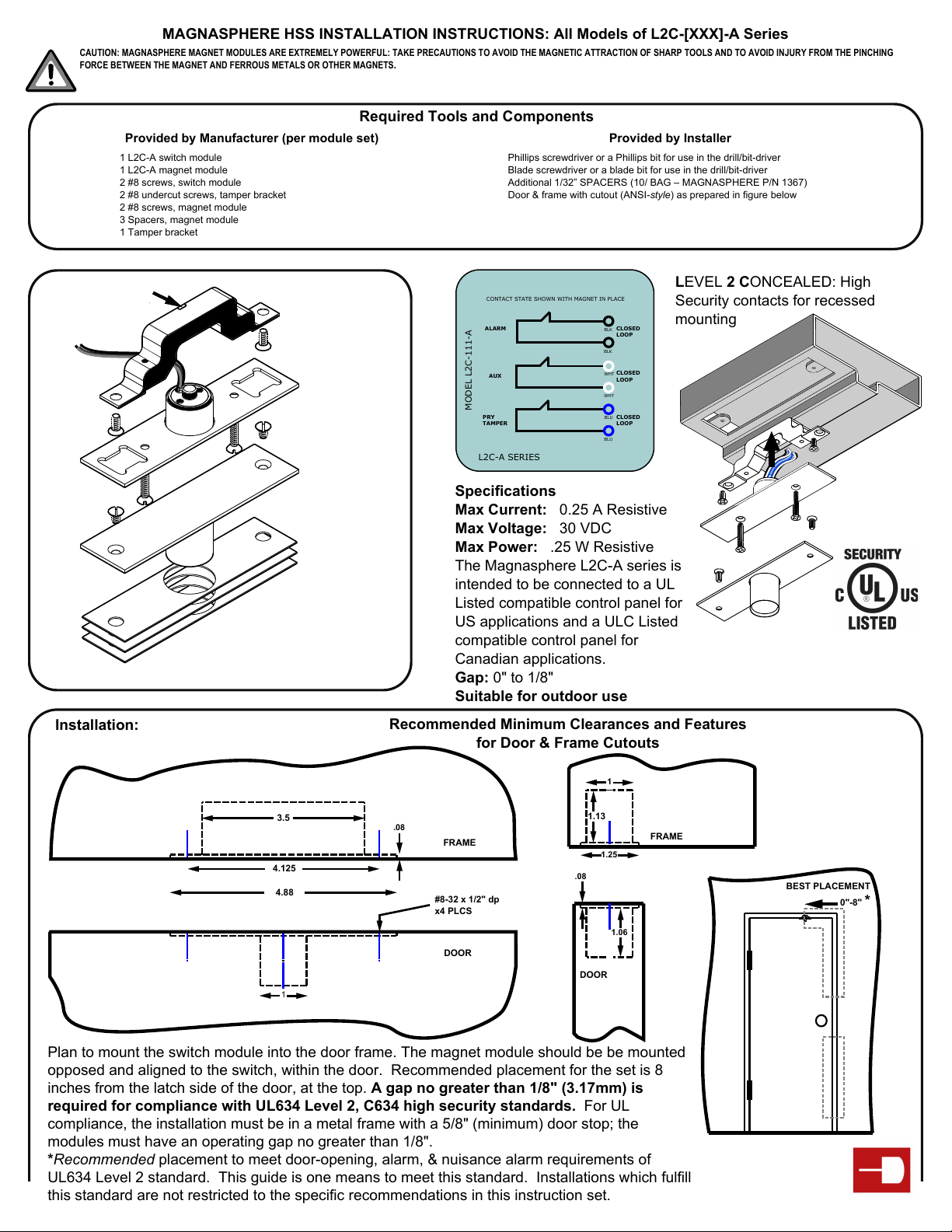
CLEARANCE RECESS
TAMPER BRACKET
#8 SCREW
Installation:
#8 SCREW
SWITCH MODULE
#8 SCREWS
MAGNET MODULE
1/32" SPACERS
CONTACT STATE SHOWN WITH MAGNET IN PLACE
ALARM
AUX
MODEL L2C-111-A
PRY
TAMPER
L2C-A SERIES
BLK
BLK
WHT
WHT
BLU
BLU
CLOSED
LOOP
CLOSED
LOOP
CLOSED
LOOP
Security contacts for recessed
mounting
Specifications
Max Current: 0.25 A Resistive
Max Voltage: 30 VDC
Max Power: .25 W Resistive
The Magnasphere L2C-A series is
intended to be connected to a UL
Listed compatible control panel for
US applications and a ULC Listed
compatible control panel for
LEVEL 2 CONCEALED: High
Canadian applications.
Gap: 0" to 1/8"
Suitable for outdoor use
Models having the following infixes are equipped
with pry-tampers, a requirement of UL634 High
Security Levels 1 and 2: -101-, -111-
Recommended Minimum Clearances and Features
for Door & Frame Cutouts
1
3.5
4.125
4.88
1
.08
FRAME
#8-32 x 1/2" dp
x4 PLCS
DOOR
1.13
FRAME
1.25
.08
1.06
DOOR
Plan to mount the switch module into the door frame. The magnet module should be be mounted
opposed and aligned to the switch, within the door. Recommended placement for the set is 8
inches from the latch side of the door, at the top. A gap no greater than 1/8" (3.17mm) is
required for compliance with UL634 Level 2, C634 high security standards. For UL
compliance, the installation must be in a metal frame with a 5/8" (minimum) door stop; the
modules must have an operating gap no greater than 1/8".
*Recommended placement to meet door-opening, alarm, & nuisance alarm requirements of
UL634 Level 2 standard. This guide is one means to meet this standard. Installations which fulfill
this standard are not restricted to the specific recommendations in this instruction set.
BEST PLACEMENT
0"-8" *
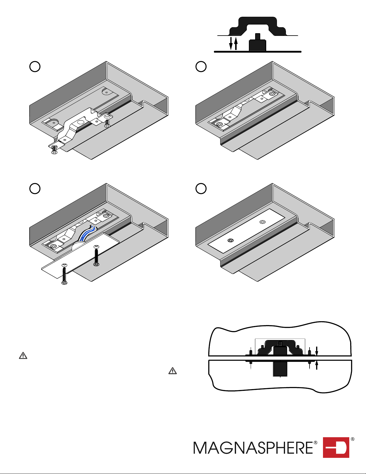
(continued) instructions:
The pry tamper (if equipped) can be tested by moving the Tamper Bracket to
and from its installed position with the switch module. This tamper will be in
alarm condition when the switch module is removed from the tamper bracket
1/16" - 1/4"
TEST
TAMPER
1
2
FRAME
SECTION
3
4
1: Fasten the Tamper Bracket as shown (2), using the undercut #8 screws
3: Plan to orient the switch, allowing the wires to pass along the clearance recess of the tamper bracket. Wire the switch module.
The tamper circuit (if equipped) must be wired to a 24-hr protection circuit. All wires must route within the metal frame.
4: Place the switch module into the frame cutout. Ensure that it is fully
nested into position. Using hand-tools, drive the screws until seated. Do
not use powered tools. Do not over-tighten the screws.
1/16" MAX
RECOMMENDED
GAP
CAUTION: Magnasphere's magnet module and anti-removal magnet
are extremely powerful: Take precautions to avoid the magnetic attraction
between the magnet and ferrous metals (or other magnets).
Determine whether magnet spacers will be necessary to achieve the
1/8" MAX
COMPLIANT
GAP
operating gap. An operating gap of 0" to 1/8" is required for compliance with
UL634 Level 2, C634 high security standard.
5: Fasten the magnet module into the door cutout. The mechanical
installation of the set is complete.
#RE 39731, #5977873, #6506987, #6603378,
12-2014 L2C-XXX-A-INST REV C
#6803845, #7944334, #8487726 & Other Patents Pending
MAGNASPHERE N22 W22931 Nancys Ct. Ste 3, Waukesha, WI 53186 tel 262.347.0711 fax 262.347.0710 www.magnasphere.com
 Loading...