


TS Series Documentation
Release 1
Magna-Power Electronics, Inc.
Jan 19, 2022


CONTENTS
1 Preface 1
1.1 Contact Magna-Power . . . . . . . . . . . . . . . . . . . . . . . . . . . . . . . . . . . . . . . . . . 1
1.2 Safety Notice . . . . . . . . . . . . . . . . . . . . . . . . . . . . . . . . . . . . . . . . . . . . . . . 1
1.3 Safety Symbols . . . . . . . . . . . . . . . . . . . . . . . . . . . . . . . . . . . . . . . . . . . . . . 3
1.4 Limited Warranty . . . . . . . . . . . . . . . . . . . . . . . . . . . . . . . . . . . . . . . . . . . . . 3
1.5 User Manual Warranty . . . . . . . . . . . . . . . . . . . . . . . . . . . . . . . . . . . . . . . . . . 4
1.6 U.S. Government Rights . . . . . . . . . . . . . . . . . . . . . . . . . . . . . . . . . . . . . . . . . 4
1.7 WEEE Directive 2002/96/EC . . . . . . . . . . . . . . . . . . . . . . . . . . . . . . . . . . . . . . 5
1.8 Declaration of Conformity . . . . . . . . . . . . . . . . . . . . . . . . . . . . . . . . . . . . . . . . 5
1.9 Document Conventions . . . . . . . . . . . . . . . . . . . . . . . . . . . . . . . . . . . . . . . . . 5
1.10 Additional Help and Feedback . . . . . . . . . . . . . . . . . . . . . . . . . . . . . . . . . . . . . . 6
2 Product Introduction 7
2.1 Features at a Glance . . . . . . . . . . . . . . . . . . . . . . . . . . . . . . . . . . . . . . . . . . . 7
2.1.1 Output Features . . . . . . . . . . . . . . . . . . . . . . . . . . . . . . . . . . . . . . . . . 8
2.1.2 Programming Features . . . . . . . . . . . . . . . . . . . . . . . . . . . . . . . . . . . . . 8
2.1.3 System Features . . . . . . . . . . . . . . . . . . . . . . . . . . . . . . . . . . . . . . . . . 8
2.2 Models . . . . . . . . . . . . . . . . . . . . . . . . . . . . . . . . . . . . . . . . . . . . . . . . . . 9
2.2.1 Model Ordering Guide . . . . . . . . . . . . . . . . . . . . . . . . . . . . . . . . . . . . . 9
2.2.2 5 kW TS Series Models . . . . . . . . . . . . . . . . . . . . . . . . . . . . . . . . . . . . . 10
2.2.3 10 kW TS Series Models . . . . . . . . . . . . . . . . . . . . . . . . . . . . . . . . . . . . 11
2.2.4 15 kW TS Series Models . . . . . . . . . . . . . . . . . . . . . . . . . . . . . . . . . . . . 12
2.2.5 20 kW TS Series Models . . . . . . . . . . . . . . . . . . . . . . . . . . . . . . . . . . . . 13
2.2.6 25 kW TS Series Models . . . . . . . . . . . . . . . . . . . . . . . . . . . . . . . . . . . . 14
2.2.7 30 kW TS Series Models . . . . . . . . . . . . . . . . . . . . . . . . . . . . . . . . . . . . 15
2.2.8 40 kW TS Series Models . . . . . . . . . . . . . . . . . . . . . . . . . . . . . . . . . . . . 16
2.2.9 50 kW TS Series Models . . . . . . . . . . . . . . . . . . . . . . . . . . . . . . . . . . . . 17
2.2.10 75 kW TS Series Models . . . . . . . . . . . . . . . . . . . . . . . . . . . . . . . . . . . . 18
2.2.11 100 kW TS Series Models . . . . . . . . . . . . . . . . . . . . . . . . . . . . . . . . . . . 19
2.2.12 Low Voltage, High Current TS Series Models . . . . . . . . . . . . . . . . . . . . . . . . . 19
2.3 Specifications . . . . . . . . . . . . . . . . . . . . . . . . . . . . . . . . . . . . . . . . . . . . . . . 19
2.3.1 AC Input Specifications . . . . . . . . . . . . . . . . . . . . . . . . . . . . . . . . . . . . . 19
2.3.2 Output Specifications . . . . . . . . . . . . . . . . . . . . . . . . . . . . . . . . . . . . . . 20
2.3.3 Programming Specifications . . . . . . . . . . . . . . . . . . . . . . . . . . . . . . . . . . 21
2.3.4 Connectivity Specifications . . . . . . . . . . . . . . . . . . . . . . . . . . . . . . . . . . . 21
2.3.5 External User I/O Specifications . . . . . . . . . . . . . . . . . . . . . . . . . . . . . . . . 22
2.3.6 Physical Specifications . . . . . . . . . . . . . . . . . . . . . . . . . . . . . . . . . . . . . 22
2.3.7 Environmental Specifications . . . . . . . . . . . . . . . . . . . . . . . . . . . . . . . . . . 24
2.3.8 Regulatory Compliance . . . . . . . . . . . . . . . . . . . . . . . . . . . . . . . . . . . . . 25
2.4 Dimensional Diagrams . . . . . . . . . . . . . . . . . . . . . . . . . . . . . . . . . . . . . . . . . . 25
i

2.4.1 TS Series - 3U Models . . . . . . . . . . . . . . . . . . . . . . . . . . . . . . . . . . . . . 25
2.4.2 TS Series - 4U Models . . . . . . . . . . . . . . . . . . . . . . . . . . . . . . . . . . . . . 25
2.4.3 TS Series - 6U Models . . . . . . . . . . . . . . . . . . . . . . . . . . . . . . . . . . . . . 25
2.4.4 TS Series - 8U Models . . . . . . . . . . . . . . . . . . . . . . . . . . . . . . . . . . . . . 25
2.4.5 TS Series - 12U Models . . . . . . . . . . . . . . . . . . . . . . . . . . . . . . . . . . . . 25
2.4.6 TS Series - 16U Models . . . . . . . . . . . . . . . . . . . . . . . . . . . . . . . . . . . . 25
2.5 Principle of Operation . . . . . . . . . . . . . . . . . . . . . . . . . . . . . . . . . . . . . . . . . . 25
2.5.1 Master Module . . . . . . . . . . . . . . . . . . . . . . . . . . . . . . . . . . . . . . . . . 25
2.5.2 Slave Module . . . . . . . . . . . . . . . . . . . . . . . . . . . . . . . . . . . . . . . . . . 29
2.6 Options . . . . . . . . . . . . . . . . . . . . . . . . . . . . . . . . . . . . . . . . . . . . . . . . . . 29
2.6.1 Blocking Diode (+BD) . . . . . . . . . . . . . . . . . . . . . . . . . . . . . . . . . . . . . 29
2.6.2 High Isolation Output (+ISO) . . . . . . . . . . . . . . . . . . . . . . . . . . . . . . . . . . 31
2.6.3 High Slew Rate Output (+HS) . . . . . . . . . . . . . . . . . . . . . . . . . . . . . . . . . 45
2.6.4 IEEE-488 GPIB (+GPIB) . . . . . . . . . . . . . . . . . . . . . . . . . . . . . . . . . . . . 47
2.6.5 LXI TCP/IP Ethernet (+LXI) . . . . . . . . . . . . . . . . . . . . . . . . . . . . . . . . . . 47
2.6.6 Ruggedized (+RUG) . . . . . . . . . . . . . . . . . . . . . . . . . . . . . . . . . . . . . . 48
2.6.7 Water Cooling (+WC) . . . . . . . . . . . . . . . . . . . . . . . . . . . . . . . . . . . . . . 48
2.7 Accessories . . . . . . . . . . . . . . . . . . . . . . . . . . . . . . . . . . . . . . . . . . . . . . . . 49
2.7.1 Cabinet and Integration . . . . . . . . . . . . . . . . . . . . . . . . . . . . . . . . . . . . . 49
2.7.2 DC Power Cables . . . . . . . . . . . . . . . . . . . . . . . . . . . . . . . . . . . . . . . . 49
2.7.3 Universal Interface Device (UID47) . . . . . . . . . . . . . . . . . . . . . . . . . . . . . . 50
2.7.4 RS485 (Converter) . . . . . . . . . . . . . . . . . . . . . . . . . . . . . . . . . . . . . . . 51
2.7.5 USB (Converter) . . . . . . . . . . . . . . . . . . . . . . . . . . . . . . . . . . . . . . . . 51
3 Installation 53
3.1 Inspection . . . . . . . . . . . . . . . . . . . . . . . . . . . . . . . . . . . . . . . . . . . . . . . . 53
3.2 Rack Installation . . . . . . . . . . . . . . . . . . . . . . . . . . . . . . . . . . . . . . . . . . . . . 53
3.2.1 Cooling Requirements . . . . . . . . . . . . . . . . . . . . . . . . . . . . . . . . . . . . . 53
3.3 AC Input Connection . . . . . . . . . . . . . . . . . . . . . . . . . . . . . . . . . . . . . . . . . . . 54
3.3.1 AC Input Current . . . . . . . . . . . . . . . . . . . . . . . . . . . . . . . . . . . . . . . . 56
3.3.2 Fuse Rating . . . . . . . . . . . . . . . . . . . . . . . . . . . . . . . . . . . . . . . . . . . 57
3.4 DC Output Connection . . . . . . . . . . . . . . . . . . . . . . . . . . . . . . . . . . . . . . . . . . 58
3.4.1 Grounding the DC Output . . . . . . . . . . . . . . . . . . . . . . . . . . . . . . . . . . . 59
3.5 Remote Sense Connection . . . . . . . . . . . . . . . . . . . . . . . . . . . . . . . . . . . . . . . . 60
3.6 Electrical Check . . . . . . . . . . . . . . . . . . . . . . . . . . . . . . . . . . . . . . . . . . . . . 62
4 Features and Functions 65
4.1 Output Regulation States . . . . . . . . . . . . . . . . . . . . . . . . . . . . . . . . . . . . . . . . . 65
4.1.1 Constant Voltage . . . . . . . . . . . . . . . . . . . . . . . . . . . . . . . . . . . . . . . . 65
4.1.2 Constant Current . . . . . . . . . . . . . . . . . . . . . . . . . . . . . . . . . . . . . . . . 65
4.2 Commands . . . . . . . . . . . . . . . . . . . . . . . . . . . . . . . . . . . . . . . . . . . . . . . . 68
4.2.1 Start . . . . . . . . . . . . . . . . . . . . . . . . . . . . . . . . . . . . . . . . . . . . . . . 68
4.2.2 Stop . . . . . . . . . . . . . . . . . . . . . . . . . . . . . . . . . . . . . . . . . . . . . . . 68
4.2.3 Clear . . . . . . . . . . . . . . . . . . . . . . . . . . . . . . . . . . . . . . . . . . . . . . 69
4.3 Protection and Diagnostics . . . . . . . . . . . . . . . . . . . . . . . . . . . . . . . . . . . . . . . . 69
4.3.1 Over Voltage Trip (OVT) . . . . . . . . . . . . . . . . . . . . . . . . . . . . . . . . . . . . 69
4.3.2 Over Current Trip (OCT) . . . . . . . . . . . . . . . . . . . . . . . . . . . . . . . . . . . . 69
4.3.3 Thermal Fault (THL) . . . . . . . . . . . . . . . . . . . . . . . . . . . . . . . . . . . . . . 70
4.3.4 Interlock (LOC) . . . . . . . . . . . . . . . . . . . . . . . . . . . . . . . . . . . . . . . . . 70
4.3.5 Phase Loss (PHL) . . . . . . . . . . . . . . . . . . . . . . . . . . . . . . . . . . . . . . . . 71
4.3.6 Program Line Fault (PGL) . . . . . . . . . . . . . . . . . . . . . . . . . . . . . . . . . . . 71
4.3.7 Fuse (FSE) . . . . . . . . . . . . . . . . . . . . . . . . . . . . . . . . . . . . . . . . . . . 71
5 Operation: Parallel and Series 73
ii

5.1 Parallel . . . . . . . . . . . . . . . . . . . . . . . . . . . . . . . . . . . . . . . . . . . . . . . . . . 73
5.1.1 Parallel - Direct . . . . . . . . . . . . . . . . . . . . . . . . . . . . . . . . . . . . . . . . . 73
5.1.2 Parallel - Master-Slave . . . . . . . . . . . . . . . . . . . . . . . . . . . . . . . . . . . . . 73
5.2 Series . . . . . . . . . . . . . . . . . . . . . . . . . . . . . . . . . . . . . . . . . . . . . . . . . . . 74
5.2.1 Series - Direct . . . . . . . . . . . . . . . . . . . . . . . . . . . . . . . . . . . . . . . . . . 74
5.2.2 Series - Master-Slave . . . . . . . . . . . . . . . . . . . . . . . . . . . . . . . . . . . . . . 74
6 Operation: Front Panel 79
6.1 Setting Set Points . . . . . . . . . . . . . . . . . . . . . . . . . . . . . . . . . . . . . . . . . . . . . 81
6.1.1 Voltage . . . . . . . . . . . . . . . . . . . . . . . . . . . . . . . . . . . . . . . . . . . . . 81
6.1.2 Current . . . . . . . . . . . . . . . . . . . . . . . . . . . . . . . . . . . . . . . . . . . . . 81
6.1.3 Period . . . . . . . . . . . . . . . . . . . . . . . . . . . . . . . . . . . . . . . . . . . . . . 81
6.2 Setting Trip Points . . . . . . . . . . . . . . . . . . . . . . . . . . . . . . . . . . . . . . . . . . . . 83
6.2.1 Over Voltage Trip . . . . . . . . . . . . . . . . . . . . . . . . . . . . . . . . . . . . . . . . 83
6.2.2 Over Current Trip . . . . . . . . . . . . . . . . . . . . . . . . . . . . . . . . . . . . . . . . 83
6.3 Configuring Set Point Source . . . . . . . . . . . . . . . . . . . . . . . . . . . . . . . . . . . . . . 83
6.3.1 Rotary (ROTARY) . . . . . . . . . . . . . . . . . . . . . . . . . . . . . . . . . . . . . . . 84
6.3.2 Keypad (KEYPAD) . . . . . . . . . . . . . . . . . . . . . . . . . . . . . . . . . . . . . . . 85
6.3.3 External Program (EXT PGM) . . . . . . . . . . . . . . . . . . . . . . . . . . . . . . . . . 85
6.3.4 Remote (REMOTE) . . . . . . . . . . . . . . . . . . . . . . . . . . . . . . . . . . . . . . . 86
6.4 Configuring Functionality . . . . . . . . . . . . . . . . . . . . . . . . . . . . . . . . . . . . . . . . 86
6.4.1 Remote Sense (REM SEN) . . . . . . . . . . . . . . . . . . . . . . . . . . . . . . . . . . . 86
6.4.2 Internal Control (INT CTL) . . . . . . . . . . . . . . . . . . . . . . . . . . . . . . . . . . 87
6.4.3 External Control (EXT CTL) . . . . . . . . . . . . . . . . . . . . . . . . . . . . . . . . . . 87
6.4.4 Interlock (LOC) . . . . . . . . . . . . . . . . . . . . . . . . . . . . . . . . . . . . . . . . . 88
6.5 Calibration . . . . . . . . . . . . . . . . . . . . . . . . . . . . . . . . . . . . . . . . . . . . . . . . 88
7 Operation: External User I/O 91
7.1 Analog Inputs . . . . . . . . . . . . . . . . . . . . . . . . . . . . . . . . . . . . . . . . . . . . . . 94
7.1.1 External Voltage Source Programming . . . . . . . . . . . . . . . . . . . . . . . . . . . . . 94
7.1.2 External Current Source Programming . . . . . . . . . . . . . . . . . . . . . . . . . . . . . 95
7.1.3 External Resistive Source Programming . . . . . . . . . . . . . . . . . . . . . . . . . . . . 95
7.2 Analog Outputs . . . . . . . . . . . . . . . . . . . . . . . . . . . . . . . . . . . . . . . . . . . . . . 96
7.3 Digital Inputs . . . . . . . . . . . . . . . . . . . . . . . . . . . . . . . . . . . . . . . . . . . . . . . 97
7.4 Digital Outputs . . . . . . . . . . . . . . . . . . . . . . . . . . . . . . . . . . . . . . . . . . . . . . 99
7.5 Reference Signals and Grounds . . . . . . . . . . . . . . . . . . . . . . . . . . . . . . . . . . . . . 101
8 Operation: Computer Programming 103
8.1 Communications Validation . . . . . . . . . . . . . . . . . . . . . . . . . . . . . . . . . . . . . . . 103
8.2 RS232 Communications . . . . . . . . . . . . . . . . . . . . . . . . . . . . . . . . . . . . . . . . . 106
8.3 LXI TCP/IP Ethernet Communications . . . . . . . . . . . . . . . . . . . . . . . . . . . . . . . . . 106
8.3.1 Address Negotiation . . . . . . . . . . . . . . . . . . . . . . . . . . . . . . . . . . . . . . 107
8.3.2 Connectivity . . . . . . . . . . . . . . . . . . . . . . . . . . . . . . . . . . . . . . . . . . 107
8.3.3 Network discovery . . . . . . . . . . . . . . . . . . . . . . . . . . . . . . . . . . . . . . . 108
8.4 IEEE-488 GPIB Communications . . . . . . . . . . . . . . . . . . . . . . . . . . . . . . . . . . . . 110
8.4.1 IEEE-488 GPIB Communications with NI MAX . . . . . . . . . . . . . . . . . . . . . . . 111
9 Calibration 113
9.1 Control Board . . . . . . . . . . . . . . . . . . . . . . . . . . . . . . . . . . . . . . . . . . . . . . 113
9.1.1 Reference Amplifier Calibration . . . . . . . . . . . . . . . . . . . . . . . . . . . . . . . . 113
9.1.2 Voltage Feedback Amplifier Calibration . . . . . . . . . . . . . . . . . . . . . . . . . . . . 113
9.1.3 Current Feedback Amplifier Calibration . . . . . . . . . . . . . . . . . . . . . . . . . . . . 113
9.2 Driver Board . . . . . . . . . . . . . . . . . . . . . . . . . . . . . . . . . . . . . . . . . . . . . . . 114
9.2.1 Over Curent Protection . . . . . . . . . . . . . . . . . . . . . . . . . . . . . . . . . . . . . 114
9.2.2 Under Voltage Protection . . . . . . . . . . . . . . . . . . . . . . . . . . . . . . . . . . . . 114
iii

10 SCPI Command Set 115
10.1 SCPI Introduction . . . . . . . . . . . . . . . . . . . . . . . . . . . . . . . . . . . . . . . . . . . . 115
10.1.1 Command Structure . . . . . . . . . . . . . . . . . . . . . . . . . . . . . . . . . . . . . . . 115
10.1.2 Data Types . . . . . . . . . . . . . . . . . . . . . . . . . . . . . . . . . . . . . . . . . . . 115
10.1.3 Termination . . . . . . . . . . . . . . . . . . . . . . . . . . . . . . . . . . . . . . . . . . . 116
10.1.4 Syntax Conventions . . . . . . . . . . . . . . . . . . . . . . . . . . . . . . . . . . . . . . . 116
10.2 SCPI Command Reference List . . . . . . . . . . . . . . . . . . . . . . . . . . . . . . . . . . . . . 116
10.3 CALibration Subsystem . . . . . . . . . . . . . . . . . . . . . . . . . . . . . . . . . . . . . . . . . 117
10.3.1 CALibrate:IDN . . . . . . . . . . . . . . . . . . . . . . . . . . . . . . . . . . . . . . . . . 117
10.3.2 CALibrate:PASS . . . . . . . . . . . . . . . . . . . . . . . . . . . . . . . . . . . . . . . . 118
10.3.3 CALibrate:POT . . . . . . . . . . . . . . . . . . . . . . . . . . . . . . . . . . . . . . . . . 118
10.3.4 CALibrate:SCALe:VOLTage . . . . . . . . . . . . . . . . . . . . . . . . . . . . . . . . . . 118
10.3.5 CALibrate:SCALe:CURRent . . . . . . . . . . . . . . . . . . . . . . . . . . . . . . . . . . 118
10.3.6 CALibrate:SCALe:INPut . . . . . . . . . . . . . . . . . . . . . . . . . . . . . . . . . . . . 118
10.3.7 CALibrate:DEFaults . . . . . . . . . . . . . . . . . . . . . . . . . . . . . . . . . . . . . . 119
10.3.8 CALibrate:STOP . . . . . . . . . . . . . . . . . . . . . . . . . . . . . . . . . . . . . . . . 119
10.4 CONFiguration Subsystem . . . . . . . . . . . . . . . . . . . . . . . . . . . . . . . . . . . . . . . . 119
10.4.1 CONTrol:INTernal . . . . . . . . . . . . . . . . . . . . . . . . . . . . . . . . . . . . . . . 119
10.4.2 CONTrol:EXTernal . . . . . . . . . . . . . . . . . . . . . . . . . . . . . . . . . . . . . . . 119
10.4.3 REMote:SENSe . . . . . . . . . . . . . . . . . . . . . . . . . . . . . . . . . . . . . . . . . 120
10.4.4 INTErlock . . . . . . . . . . . . . . . . . . . . . . . . . . . . . . . . . . . . . . . . . . . . 120
10.4.5 CONFigure:SETPT . . . . . . . . . . . . . . . . . . . . . . . . . . . . . . . . . . . . . . . 120
10.5 MEASure Subsystem . . . . . . . . . . . . . . . . . . . . . . . . . . . . . . . . . . . . . . . . . . . 121
10.5.1 MEASure:VOLTage? . . . . . . . . . . . . . . . . . . . . . . . . . . . . . . . . . . . . . . 121
10.5.2 MEASure:CURRent? . . . . . . . . . . . . . . . . . . . . . . . . . . . . . . . . . . . . . . 121
10.6 MODulation Commands . . . . . . . . . . . . . . . . . . . . . . . . . . . . . . . . . . . . . . . . . 121
10.6.1 MODulation:TYPE:SELect . . . . . . . . . . . . . . . . . . . . . . . . . . . . . . . . . . . 121
10.6.2 MODulation:TABLe . . . . . . . . . . . . . . . . . . . . . . . . . . . . . . . . . . . . . . 122
10.6.3 MODulation:SAVE . . . . . . . . . . . . . . . . . . . . . . . . . . . . . . . . . . . . . . . 123
10.6.4 MODulation:TABLe:LOAD . . . . . . . . . . . . . . . . . . . . . . . . . . . . . . . . . . 123
10.7 OUTPut Subsystem . . . . . . . . . . . . . . . . . . . . . . . . . . . . . . . . . . . . . . . . . . . 123
10.7.1 OUTPut? . . . . . . . . . . . . . . . . . . . . . . . . . . . . . . . . . . . . . . . . . . . . 123
10.7.2 OUTPut:ARM . . . . . . . . . . . . . . . . . . . . . . . . . . . . . . . . . . . . . . . . . 124
10.7.3 OUTPut:START . . . . . . . . . . . . . . . . . . . . . . . . . . . . . . . . . . . . . . . . 124
10.7.4 OUTPut:STOP . . . . . . . . . . . . . . . . . . . . . . . . . . . . . . . . . . . . . . . . . 124
10.7.5 OUTPut:PROTection:CLEar . . . . . . . . . . . . . . . . . . . . . . . . . . . . . . . . . . 125
10.8 SOURce Subsystem . . . . . . . . . . . . . . . . . . . . . . . . . . . . . . . . . . . . . . . . . . . 125
10.8.1 VOLTage and VOLTage:TRIGgered . . . . . . . . . . . . . . . . . . . . . . . . . . . . . . 125
10.8.2 VOLTage:PROTection . . . . . . . . . . . . . . . . . . . . . . . . . . . . . . . . . . . . . 125
10.8.3 CURRent and CURRent:TRIGgered . . . . . . . . . . . . . . . . . . . . . . . . . . . . . . 126
10.8.4 CURRent:PROTection . . . . . . . . . . . . . . . . . . . . . . . . . . . . . . . . . . . . . 126
10.8.5 PERiod . . . . . . . . . . . . . . . . . . . . . . . . . . . . . . . . . . . . . . . . . . . . . 127
10.8.6 Save . . . . . . . . . . . . . . . . . . . . . . . . . . . . . . . . . . . . . . . . . . . . . . . 127
10.8.7 RECall:MEMory . . . . . . . . . . . . . . . . . . . . . . . . . . . . . . . . . . . . . . . . 128
10.9 STATus Subsystem . . . . . . . . . . . . . . . . . . . . . . . . . . . . . . . . . . . . . . . . . . . . 128
10.9.1 *CLS . . . . . . . . . . . . . . . . . . . . . . . . . . . . . . . . . . . . . . . . . . . . . . 128
10.9.2 *ESE? . . . . . . . . . . . . . . . . . . . . . . . . . . . . . . . . . . . . . . . . . . . . . . 128
10.9.3 *ESR? . . . . . . . . . . . . . . . . . . . . . . . . . . . . . . . . . . . . . . . . . . . . . . 129
10.9.4 *IDN? . . . . . . . . . . . . . . . . . . . . . . . . . . . . . . . . . . . . . . . . . . . . . . 129
10.9.5 *OPC . . . . . . . . . . . . . . . . . . . . . . . . . . . . . . . . . . . . . . . . . . . . . . 129
10.9.6 *RST . . . . . . . . . . . . . . . . . . . . . . . . . . . . . . . . . . . . . . . . . . . . . . 130
10.9.7 *SRE . . . . . . . . . . . . . . . . . . . . . . . . . . . . . . . . . . . . . . . . . . . . . . 130
10.9.8 *STB . . . . . . . . . . . . . . . . . . . . . . . . . . . . . . . . . . . . . . . . . . . . . . 131
10.9.9 STATus:OPERation:CONDition? . . . . . . . . . . . . . . . . . . . . . . . . . . . . . . . . 131
iv

10.9.10 STATus:QUEStionable:CONDition? . . . . . . . . . . . . . . . . . . . . . . . . . . . . . . 131
10.10 SYSTem Subsystem . . . . . . . . . . . . . . . . . . . . . . . . . . . . . . . . . . . . . . . . . . . 132
10.10.1 SYSTem:VERSion? . . . . . . . . . . . . . . . . . . . . . . . . . . . . . . . . . . . . . . . 132
10.10.2 SYSTem:ERRor? . . . . . . . . . . . . . . . . . . . . . . . . . . . . . . . . . . . . . . . . 132
10.10.3 SYSTem:COMMunicate:NETwork:VERSion? . . . . . . . . . . . . . . . . . . . . . . . . . 133
10.10.4 SYSTem:COMMunicate:NETwork:MAC? . . . . . . . . . . . . . . . . . . . . . . . . . . . 133
10.10.5 SYSTem:COMMunicate:NETwork:SER . . . . . . . . . . . . . . . . . . . . . . . . . . . . 133
10.10.6 SYSTem:COMMunicate:NETwork:ADDRess . . . . . . . . . . . . . . . . . . . . . . . . . 133
10.10.7 SYSTem:COMMunicate:NETwork:GATE . . . . . . . . . . . . . . . . . . . . . . . . . . . 134
10.10.8 SYSTem:COMMunicate:NETwork:SUBNet . . . . . . . . . . . . . . . . . . . . . . . . . . 134
10.10.9 SYSTem:COMMunicate:NETwork:PORT . . . . . . . . . . . . . . . . . . . . . . . . . . . 134
10.10.10SYSTem:COMMunicate:NETwork:HOSTname . . . . . . . . . . . . . . . . . . . . . . . . 135
10.10.11SYSTem:COMMunicate:NETwork:DHCP . . . . . . . . . . . . . . . . . . . . . . . . . . . 135
10.10.12SYSTem:COMMunicate:GPIB:VERSion . . . . . . . . . . . . . . . . . . . . . . . . . . . 135
10.10.13SYSTem:COMMunicate:GPIB:ADDRess . . . . . . . . . . . . . . . . . . . . . . . . . . . 135
10.11 TRIGger Commands . . . . . . . . . . . . . . . . . . . . . . . . . . . . . . . . . . . . . . . . . . . 136
10.11.1 TRIGger . . . . . . . . . . . . . . . . . . . . . . . . . . . . . . . . . . . . . . . . . . . . . 136
10.11.2 INITiate . . . . . . . . . . . . . . . . . . . . . . . . . . . . . . . . . . . . . . . . . . . . . 136
10.11.3 ABORt . . . . . . . . . . . . . . . . . . . . . . . . . . . . . . . . . . . . . . . . . . . . . 136
v

vi

CHAPTER
ONE
PREFACE
Thank you for choosing a Magna-Power Electronics product. This document provides user, service, and programming
information the TS Series MagnaDC programmable DC power supply. If you have any suggestions or feedback for this
document, please contact Magna-Power at feedback@magna-power.com.
1.1 Contact Magna-Power
Magna-Power support can be contacted for service, technical support, or spare parts:
• By Phone: +1-908-237-2200
• By Email: support@magna-power.com
Visit magna-power.com/support for more support resources and information about contacting Magna-Power worldwide.
1.2 Safety Notice
The following general safety precautions must be observed during all phases of operation of this instrument. Failure to
comply with these precautions or with specific warnings elsewhere in this manual violates safety standards of design,
manufacture, and intended use of the instrument. Neither Magna-Power Electronics nor any of the associated sales
organizations accept responsibility for personal injury, consequential injury, loss, or damage resulting from improper
use of the equipment and accessories.
Installation and service must be performed only by properly trained and qualified personnel who are aware of dealing
with electrical hazards. Ensure that the AC power line ground is properly connected to the MagnaDC power supply
chassis. Furthermore, other power grounds, including those connected to application maintenance equipment, must be
grounded for both personnel and equipment safety.
This product is a Safety Class 1 instrument, provided with a protective earth terminal. The protective features of this
product may be impaired if it is used in a manner not specified in the operation instructions.
Warning: Residiual voltage. Lethal voltages may be present inside the MagnaDC power supply even when the
AC input voltage is disconnected. Only properly trained and qualified personnel should remove covers and access
the inside of the MagnaDC power supply.
During normal operation, the operator does not have access to hazardous voltages within the product’s chassis. Depending on the application, high voltages hazardous to human safety may be present on the DC power terminals. Ensure
that the DC power cables are properly labeled as to the safety hazards and that any inadvertent contact with hazardous
voltages is eliminated.
1

TS Series Documentation, Release 1
Do not install substitute parts or perform unauthorized maintenance on the product.
These operating instructions form an integral part of the equipment and must be available to the operating personnel at
all times. All the safety instructions and advice notes are to be followed.
Warning: General. Do not use this product in any manner not specified by the manufacturer. The protective
features of this product may be impaired if it is used in a manner not specified in the operating instructions.
Warning: Environmental Conditions. Never use the instrument outside of the specified environmental conditions described in the Environmental Characteristics of the specifications.
Warning: Ground the Instrument. This product is provided with protective earth terminals. To minimize shock
hazard, the instrument must be connected to the AC mains through a grounded power cable, with the ground wire
firmly connected to an electrical ground (safety ground) at the power outlet. Any interruption of the protective
(grounding) conductor or disconnection of the protective earth terminal will cause a potential shock hazard that
could result in injury or death.
Warning: Before Applying Power. Verify that all safety precautions are taken. All connections must be made
with the unit turned off, and must be performed by qualified personnel who are aware of the hazards involved.
Improper actions can cause fatal injury as well as equipment damage. Note the instrument’s external markings
described under “Safety Symbols”.
Warning: Do Not Operate in an Explosive Atmosphere. Do not operate the instrument in the presence of
flammable gases or fumes.
Warning: Do Not Remove the Instrument Cover. Only qualified, service-trained personnel who are aware of
the hazards involved should remove instrument covers. Disconnect the power cable and any external circuits before
removing instrument covers.
Warning: Do Not Modify the Instrument. Do not install substitute parts or perform any unauthorized modification to the product, except with the direction of Magna-Power support personnel. Return the product to a
Magna-Power authorized service center for repair.
Warning: In Case of Damage. Instruments that are not functioning correctly, appear damaged or defective
should be made inoperative and secured against unintended operation until they can be repaired by qualified service
personnel.
2 Chapter 1. Preface
1.3 Safety Symbols
Caution. Refer to documentation or notation for more information before proceeding.
Caution, risk of electric shock. Refer to documentation or notation for more information before proceeding.
TS Series Documentation, Release 1
Direct current
Alternating current
Caution, hot surface.
Earth ground terminal.
The ETL mark, which is a registered trademark of Intertek.
The CE mark, which is a registered trademark of the European Community.
1.4 Limited Warranty
The following is made in lieu of all warranties expressed or implied.
Magna-Power Electronics, Inc. warranties its products to be free of manufacturing defects for a period of two years
from date of original shipment from its factory. Magna-Power Electronics, Inc. will repair, replace, or refund the
purchase price at its discretion, which upon examination by Magna-Power Electronics, Inc., is determined to be defective in material or workmanship, providing such claimed defective material is returned upon written authorization of
Magna-Power Electronics, Inc., freight and duties prepaid.
1.3. Safety Symbols 3

TS Series Documentation, Release 1
For products failing within the first 30 days of the warranty period, Magna-Power Electronics, Inc. will return the
repaired product at its expense using a standard ground shipping method; after 30 days of the warranty period, the
repaired product will be returned at the customer’s expense using the customer’s requested shipping method.
Damage due to corrosion, customer alterations, excessive dust, extreme environmental or electrical conditions, and/or
misuse will be evaluated upon inspection. If inspection reveals that the cause of damage is not due to materials or
workmanship, repair of the product will be treated on a non-warranty basis.
All electrical, commercial supply parts, and items not manufactured by Magna-Power Electronics, Inc. shall carry
the warranty of the original manufacturer and no more, but under no circumstances to exceed the warranty period.
Replacement parts shall be warranted for a period of 90 days. Warranty labor shall only apply if the product, assembly,
or part is returned to the factory freight prepaid and insured. Damage or breakage while in transit is not covered by this
warranty.
Magna-Power Electronics, Inc. assumes no responsibility to Buyer for labor to diagnose and remove defective product
and installation of replacement product. Fur thermore, Magna-Power Electronics, Inc. is not liable to Buyer or to any
third party for consequential or incidental damages under any circumstances, whether due to defect in the product, due
to delay or failure of delivery, due to a failure of the product to perform as specified, or for any other reason or cause.
Buyer and Magna-Power Electronics, Inc. agree that Buyer’s sole remedy and Magna-Power Electronics, Inc.’s sole
liability to Buyer is limited to repair, replacement, or refund of the purchase price of the product as described herein,
whether Buyer’s claim arises out of contract or in tort.
All claims against the warranty shall be the final determination of Magna-Power Electronics, Inc.
1.5 User Manual Warranty
The material contained in this document is provided “as is,” and is subject to being changed, without notice, in future
editions. Further, to the maximum extent permitted by applicable law, Magna-Power disclaims all warranties, either
express or implied, with regard to this manual and any information contained herein, including but not limited to the
implied warranties of merchantability and fitness for a particular purpose. Magna-Power shall not be liable for errors
or for incidental or consequential damages in connection with the furnishing, use, or per formance of this document
or of any information contained herein. Should Magna-Power and the user have a separate written agreement with
warranty terms covering the material in this document that conflict with these terms, the warranty terms in the separate
agreement shall control.
1.6 U.S. Government Rights
The Software is “commercial computer software,” as defined by Federal Acquisition Regulation (“FAR”) 2.101. Pursuant to FAR 12.212 and 27.405-3 and Department of Defense FAR Supplement (“DFARS”) 227.7202, the U.S. government acquires commercial computer software under the same terms by which the software is customarily provided
to the public. Accordingly, Magna-Power provides the Software to U.S. government customers under its standard commercial license, which is embodied in its End User License Agreement (EULA). The license set forth in the EULA
represents the exclusive authority by which the U.S. government may use, modify, distribute, or disclose the Software.
The EULA and the license set forth therein, does not require or permit, among other things, that Magna-Power: (1)
Furnish technical information related to commercial computer software or commercial computer software documentation that is not customarily provided to the public; or (2) Relinquish to, or otherwise provide, the government rights
in excess of these rights customarily provided to the public to use, modify, reproduce, release, perform, display, or
disclose commercial computer software or commercial computer software documentation. No additional government
requirements beyond those set forth in the EULA shall apply, except to the extent that those terms, rights, or licenses
are explicitly required from all providers of commercial computer software pursuant to the FAR and the DFARS and
are set forth specifically in writing elsewhere in the EULA. Magna-Power shall be under no obligation to update, revise
or otherwise modify the Software. With respect to any technical data as defined by FAR 2.101, pursuant to FAR 12.211
4 Chapter 1. Preface

TS Series Documentation, Release 1
and 27.404.2 and DFARS 227.7102, the U.S. government acquires no greater than Limited Rights as defined in FAR
27.401 or DFAR 227.7103-5 (c), as applicable in any technical data
1.7 WEEE Directive 2002/96/EC
This product complies with the Waste Electrical and Electronic Equipment (WEEE) Directive 2002/96/EC marking
requirement. The affixed product label (see below) indicates that you must not discard this electrical/electronic product
in domestic household waste.
Product Category: With reference to the equipment types in the WEEE directive Annex 1, this product is classified as
“Monitoring and Control instrumentation” product.
Do not dispose products in domestic household waste.
To return unwanted products, contact Magna-Power Electronics.
1.8 Declaration of Conformity
Magna-Power Electronics declares on its sole responsibility that the TS Series MagnaDC programmable DC power
supply complies with the essential requirement of the relevant European Directives, and is eligible to carry the CE
mark.
For more details, please review the TS Series Declaration of Conformity.
1.9 Document Conventions
This user’s manual uses several conventions to highlight certain words and phrases and draw attention to specific pieces
of information.
Note: Notes are tips, shortcuts or alternative approaches to the task at hand. Ignoring a note should have no negative
consequences, but you might miss out on a time saving procedure.
Warning: The warning sign denotes a hazard, calling attention to a procedure or practice. If a warning is not
correctly performed or adhered to, it could result in personal injury. Do not proceed beyond a warning sign until
the conditions are fully understood or met.
Caution: The caution sign denotes a hazard, calling attention to a procedure or practice. If a caution is not
correctly performed or adhered to, it could result in damage to the product. Do not proceed beyond a caution sign
until the conditions are fully understood or met.
1.7. WEEE Directive 2002/96/EC 5

TS Series Documentation, Release 1
Source-code listings are also set in mono-spaced roman but add syntax highlighting as follows:
#!/usr/bin/python
# -*- coding: utf-8 -*-
from serial import Serial
class Magna(Serial):
def __init__(self, port, expected_serial_number=None, log=None):
super(Magna, self).__init__(port, baudrate=19200, timeout=2.0)
self.log = log if log else self.magna_log
self.write('*CLS\r\n')
1.10 Additional Help and Feedback
For additional help or to provide feedback about the product’s design and features, please contact: sup-
port@magna-power.com.
6 Chapter 1. Preface

CHAPTER
TWO
PRODUCT INTRODUCTION
2.1 Features at a Glance
The TS Series offers many models spanning a wide voltage and current range, while still maintaining among the highest
power density rack-mount packaging. The TS Series covers voltages from 5 Vdc up to 6000 Vdc (floating) and current
levels from 1.2 Adc up to 8000 Adc. Models 5 kW to 15 kW are available in a 3U chassis, models 20 kW and 25 kW
are available in a 4U chassis, models 30 kW are available in a 6U chassis, models 40 kW and 50 kW are available in an
8U chassis with removable casters, models 75 kW models are available in a 12U chassis with removable casters, and
100 kW models are available in a 16U chassis with removable casters. In addition, there are several special low voltage
high current models, enabling a more cost-effective solution for these requirements. All TS Series power supplies come
standard with isolated 37-pin external I/O, RS232, Remote Interface Software, IVI drivers, and LabVIEW drivers for
integration into a variety of programming environment.
A quick summary of the TS Series key features:
• SCPI Remote Programming API
• High Accuracy Measurements
• Master-Slave Functionality
• Remote Sensing
• 37-Pin External User I/O
• RS232 Interface
• Ethernet and GPIB Available
• 0-10V External Analog Inputs
• Programmable Protection Limits
• Fast Transient Response
• Remote Interface Software
• NI LabVIEW™ and IVI Driver
• Interlock Shutdown Input
• Designed and manufactured in the USA
7

TS Series Documentation, Release 1
2.1.1 Output Features
• Robust Power Conversion Topology - All MagnaDC programmable DC power supplies utilize high-frequency
IGBT-based power processing in current-fed topology. This topology adds an additional stage over the conventional voltage-fed topology for enhanced control and systemprotection, ensuring that even under a fault condition,
the power supply will self-protect. Due to the self-protecting characteristics of this topology, the possibility of
fast rising current spikes and magnetic core saturation is elimated. Every power supply is tested at 90% to 125%
nominal line to ensure satisfactory operation even under the worst line voltage conditions.
• Fast Transient Response - Quick response to load changes, with 2 ms to recover within ±1% of regulated output
with a 50% to 100% or 100% to 50% step load change.
• Programmable Output Protection - Programmable over voltage trip (OVT) and over current trip (OCT) allow
the user to prog ram in soft latching fault trips when the threshold is exceeded. OVT and OCT settings can be
programmed from 10% to 110% of the unit’s max ratings.
• Wired Remote Sensing with Smart Detection - A set of remote sensing terminals are provided to sense voltage
at the load and compensate for voltage drop in the load cables. Compensation is provided up to 3% above the
unit’s max rated voltage.
• Leadless Remote Sensing - Using the product’s integrated modulation functionality, automatically compensate
for voltage as a function of current. When the impedance between the power supply and load is known, this
feature allows for remote sensing without leads, up to the max ratings of the product.
2.1.2 Programming Features
• High Accuracy Programming and Measurment - ± 0.075% of max rated voltage or current programming
accuracy to ensures the output is following the desired programmed set point. ± 0.2% of max rated voltage
or current readback accuracy ensures high accuracy measurements. A NIST traceable calibration certificate is
provided at no charge with all new units.
• Simultaneous Measurement Interfaces - Voltage and current measurements are available simultaneously from
the front panel meters, dedicated 0-10V analog output, and by computer command.
• SCPI Remote Programming API - Compatible with the Standard Commands for Programmable Instruments
(SCPI), allowing raw ASCII text commands to control all features, functions, and configurations of the product.
Commands are consistent across all available interfaces.
• 37-pin External User I/O Port - An isolated 37-pin external user I/O port is provided, which includes a vari-
ety of analog and digital inputs and outputs. Voltage, current, over voltage and over current set points can be
set by applying a 0-10V analog signal. Each diagnostic condition is given a designated pin, which reads +5V
when active. Reference +5V and +10V signals are provided, eliminating the need for external voltage signals
and allowing the use of dry contacts. All these pins are isolated from the output terminals and referenced to
earth-ground as standard—no additional isolation equipment or options necessary.
2.1.3 System Features
• AC Mechanical Contactor with In-rush Limiter - An integrated mechanical contactor on the AC input circuit
ensures the product is not processing power when in standby or fault. This contactor, coupled with step-start
in-rush limiter circuitry, ensures no in-rush current will exceed peak input current rating of the product.
• Designed for Safety - Extensive diagnostic functions are provided, including: AC phase loss (not on SL/XR Se-
ries), excessive thermal conditions, over voltage trip (programmable), over current trip (programmable), cleared
fuse (not on SL/XR Series), excessive program line voltage, and interlock fault. A dedicated +5V interlock input
pin and included +5V reference on all models, external emergency stop systems can be easily integrated using
an external contact.
8 Chapter 2. Product Introduction
TS Series Documentation, Release 1
• High-Performance Plug and Play Master-Slaving - Power capability can easily expanded with additional units
by using the plug and play UID47 master-slaving device. In the MagnaDC master-slave scheme, the master sends
gate drive signals directly to the slave units. This strategy eliminates the noise suceptibility commonly found
when sending analog control references over long distances, in addition to enabling consistent performance by
maintaining a single control loop.
• Tailor Performance with Integrated Options - A variety of configured-to-order options are available for Mag-
naDC programmable power supplies are designed to be flexible, depending on the application’s requirements.
• Designed and Manufactured in the USA - For complete control of quality, MagnaDC programmable DC power
supplies are designed and manufactured at Magna-Power’s vertically integrated USA manufacturing facility in
Flemington, New Jersey. Heat-sinks and chassis are machined from aluminum. All sheet metal is fabricated and
powder coated in-house. Magnetics are wound-to-order from validated designs based on a model’s voltage and
current. An automated surface-mount production line places components on printed circuit boards for control,
driver, auxiliary power, and display circuits. And finally after assembly, products undergo comprehensive test
and NIST-traceable calibration, followed by an extended burn-in period.
2.2 Models
The following tables list the available models in the TS Series MagnaDC power supply. Ripple is specified for standard
models. Ripple will be higher for models with the High Slew Rate Output (+HS). Low voltage, high current models
have a size size and input current rating that differ from the rated specifications for models within the same power level.
Efficiency is measured at the model’s maximum ratings.
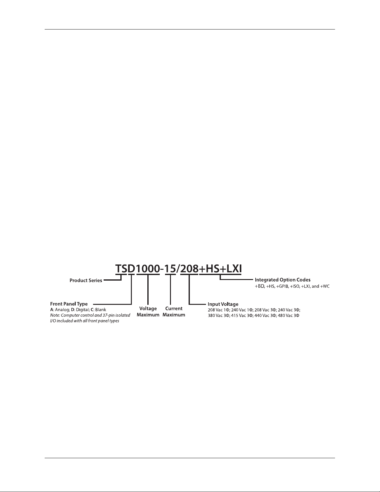
2.2.1 Model Ordering Guide
The following ordering guide defines how an TS Series MagnaDC power supply is defined:
Fig. 2.1: TS Series MagnaDC power supply Model Ordering Guide
2.2. Models 9

TS Series Documentation, Release 1
2.2.2 5 kW TS Series Models
Model Maximum Voltage Maximum Current Ripple Efficiency
TSD5-900 5 Vdc 900 Adc 50 mVrms 84%
TSD8-600 8 Vdc 600 Adc 40 mVrms 85%
TSD10-500 10 Vdc 500 Adc 40 mVrms 87%
TSD16-300 16 Vdc 300 Adc 35 mVrms 87%
TSD20-250 20 Vdc 250 Adc 40 mVrms 88%
TSD25-200 25 Vdc 200 Adc 40 mVrms 89%
TSD32-150 32 Vdc 150 Adc 40 mVrms 89%
TSD40-125 40 Vdc 125 Adc 40 mVrms 89%
TSD50-100 50 Vdc 100 Adc 50 mVrms 89%
TSD60-83 60 Vdc 83 Adc 60 mVrms 87%
TSD80-62 80 Vdc 62 Adc 60 mVrms 90%
TSD100-50 100 Vdc 50 Adc 60 mVrms 90%
TSD125-40 125 Vdc 40 Adc 100 mVrms 90%
TSD160-31 160 Vdc 31 Adc 120 mVrms 90%
TSD200-25 200 Vdc 25 Adc 125 mVrms 91%
TSD250-20 250 Vdc 20 Adc 130 mVrms 91%
TSD300-16 300 Vdc 16 Adc 160 mVrms 91%
TSD375-13 375 Vdc 13 Adc 170 mVrms 92%
TSD400-12 400 Vdc 12 Adc 180 mVrms 92%
TSD500-10 500 Vdc 10 Adc 220 mVrms 92%
TSD600-8 600 Vdc 8 Adc 250 mVrms 92%
TSD800-6 800 Vdc 6 Adc 300 mVrms 92%
TSD1000-5 1000 Vdc 5 Adc 350 mVrms 92%
TSD1250-4 1250 Vdc 4 Adc 375 mVrms 92%
TSD1500-3.3 1500 Vdc 3.3 Adc 400 mVrms 92%
TSD2000-2.5 2000 Vdc 2.5 Adc 600 mVrms 92%
TSD3000-1.6 3000 Vdc 1.6 Adc 650 mVrms 92%
TSD4000-1.2 4000 Vdc 1.2 Adc 700 mVrms 92%
10 Chapter 2. Product Introduction

2.2.3 10 kW TS Series Models
Model Maximum Voltage Maximum Current Ripple Efficiency
TSD10-900 10 Vdc 900 Adc 40 mVrms 87%
TSD16-600 16 Vdc 600 Adc 35 mVrms 87%
TSD20-500 20 Vdc 500 Adc 40 mVrms 88%
TSD25-400 25 Vdc 400 Adc 40 mVrms 89%
TSD32-300 32 Vdc 300 Adc 40 mVrms 89%
TSD40-250 40 Vdc 250 Adc 40 mVrms 89%
TSD50-200 50 Vdc 200 Adc 50 mVrms 89%
TSD60-166 60 Vdc 166 Adc 60 mVrms 87%
TSD80-124 80 Vdc 124 Adc 60 mVrms 90%
TSD100-100 100 Vdc 100 Adc 60 mVrms 90%
TSD125-80 125 Vdc 80 Adc 100 mVrms 90%
TSD160-62 160 Vdc 62 Adc 120 mVrms 90%
TSD200-50 200 Vdc 50 Adc 125 mVrms 91%
TSD250-40 250 Vdc 40 Adc 130 mVrms 91%
TSD300-32 300 Vdc 32 Adc 160 mVrms 91%
TSD375-26 375 Vdc 26 Adc 170 mVrms 92%
TSD400-24 400 Vdc 24 Adc 180 mVrms 92%
TSD500-20 500 Vdc 20 Adc 220 mVrms 92%
TSD600-16 600 Vdc 16 Adc 250 mVrms 92%
TSD800-12 800 Vdc 12 Adc 300 mVrms 92%
TSD1000-10 1000 Vdc 10 Adc 350 mVrms 92%
TSD1250-8 1250 Vdc 8 Adc 375 mVrms 92%
TSD1500-6.6 1500 Vdc 6.6 Adc 400 mVrms 92%
TSD2000-5 2000 Vdc 5 Adc 600 mVrms 92%
TSD3000-3.2 3000 Vdc 3.2 Adc 650 mVrms 92%
TSD4000-2.4 4000 Vdc 2.4 Adc 700 mVrms 92%
TS Series Documentation, Release 1
2.2. Models 11

TS Series Documentation, Release 1
2.2.4 15 kW TS Series Models
Model Maximum Voltage Maximum Current Ripple Efficiency
TSD16-900 16 Vdc 900 Adc 35 mVrms 87%
TSD20-750 20 Vdc 750 Adc 40 mVrms 88%
TSD25-600 25 Vdc 600 Adc 40 mVrms 89%
TSD32-450 32 Vdc 450 Adc 40 mVrms 89%
TSD40-375 40 Vdc 375 Adc 40 mVrms 89%
TSD50-300 50 Vdc 300 Adc 50 mVrms 89%
TSD60-249 60 Vdc 249 Adc 60 mVrms 87%
TSD80-186 80 Vdc 186 Adc 60 mVrms 90%
TSD100-150 100 Vdc 150 Adc 60 mVrms 90%
TSD125-120 125 Vdc 120 Adc 100 mVrms 90%
TSD160-93 160 Vdc 93 Adc 120 mVrms 90%
TSD200-75 200 Vdc 75 Adc 125 mVrms 91%
TSD250-60 250 Vdc 60 Adc 130 mVrms 91%
TSD300-48 300 Vdc 48 Adc 160 mVrms 91%
TSD375-39 375 Vdc 39 Adc 170 mVrms 92%
TSD400-36 400 Vdc 36 Adc 180 mVrms 92%
TSD500-30 500 Vdc 30 Adc 220 mVrms 92%
TSD600-24 600 Vdc 24 Adc 250 mVrms 92%
TSD800-18 800 Vdc 18 Adc 300 mVrms 92%
TSD1000-15 1000 Vdc 15 Adc 350 mVrms 92%
TSD1250-12 1250 Vdc 12 Adc 375 mVrms 92%
TSD1500-9.9 1500 Vdc 9.9 Adc 400 mVrms 92%
TSD2000-7.5 2000 Vdc 7.5 Adc 600 mVrms 92%
TSD3000-4.8 3000 Vdc 4.8 Adc 650 mVrms 92%
TSD4000-3.6 4000 Vdc 3.6 Adc 700 mVrms 92%
12 Chapter 2. Product Introduction

2.2.5 20 kW TS Series Models
Model Maximum Voltage Maximum Current Ripple Efficiency
TSD10-2000 10 Vdc 2000 Adc 40 mVrms 87%
TSD20-1000 20 Vdc 1000 Adc 40 mVrms 88%
TSD25-800 25 Vdc 800 Adc 40 mVrms 89%
TSD32-625 32 Vdc 625 Adc 40 mVrms 89%
TSD40-500 40 Vdc 500 Adc 40 mVrms 89%
TSD50-400 50 Vdc 400 Adc 50 mVrms 89%
TSD60-333 60 Vdc 333 Adc 60 mVrms 87%
TSD80-250 80 Vdc 250 Adc 60 mVrms 90%
TSD100-200 100 Vdc 200 Adc 60 mVrms 90%
TSD125-160 125 Vdc 160 Adc 100 mVrms 90%
TSD160-125 160 Vdc 125 Adc 120 mVrms 90%
TSD200-100 200 Vdc 100 Adc 125 mVrms 91%
TSD250-80 250 Vdc 80 Adc 130 mVrms 91%
TSD300-66.6 300 Vdc 66.6 Adc 160 mVrms 91%
TSD375-53.3 375 Vdc 53.3 Adc 170 mVrms 92%
TSD400-50 400 Vdc 50 Adc 180 mVrms 92%
TSD500-40 500 Vdc 40 Adc 220 mVrms 92%
TSD600-33.3 600 Vdc 33.3 Adc 250 mVrms 92%
TSD800-25 800 Vdc 25 Adc 300 mVrms 92%
TSD1000-20 1000 Vdc 20 Adc 350 mVrms 92%
TSD1250-16 1250 Vdc 16 Adc 375 mVrms 92%
TSD1500-13.3 1500 Vdc 13.3 Adc 400 mVrms 92%
TSD2000-10 2000 Vdc 10 Adc 600 mVrms 92%
TSD3000-6.6 3000 Vdc 6.6 Adc 650 mVrms 92%
TSD4000-5 4000 Vdc 5 Adc 700 mVrms 92%
TS Series Documentation, Release 1
2.2. Models 13

TS Series Documentation, Release 1
2.2.6 25 kW TS Series Models
Model Maximum Voltage Maximum Current Ripple Efficiency
TSD20-1250 20 Vdc 1250 Adc 40 mVrms 88%
TSD25-1000 25 Vdc 1000 Adc 40 mVrms 89%
TSD32-781 32 Vdc 781 Adc 40 mVrms 89%
TSD40-625 40 Vdc 625 Adc 40 mVrms 89%
TSD50-500 50 Vdc 500 Adc 50 mVrms 89%
TSD60-416 60 Vdc 416 Adc 60 mVrms 87%
TSD80-312.5 80 Vdc 312.5 Adc 60 mVrms 90%
TSD100-250 100 Vdc 250 Adc 60 mVrms 90%
TSD125-200 125 Vdc 200 Adc 100 mVrms 90%
TSD160-156 160 Vdc 156 Adc 120 mVrms 90%
TSD200-125 200 Vdc 125 Adc 125 mVrms 91%
TSD250-100 250 Vdc 100 Adc 130 mVrms 91%
TSD300-83.3 300 Vdc 83.3 Adc 160 mVrms 91%
TSD375-66.6 375 Vdc 66.6 Adc 170 mVrms 92%
TSD400-62.5 400 Vdc 62.5 Adc 180 mVrms 92%
TSD500-50 500 Vdc 50 Adc 220 mVrms 92%
TSD600-41.6 600 Vdc 41.6 Adc 250 mVrms 92%
TSD800-31.2 800 Vdc 31.2 Adc 300 mVrms 92%
TSD1000-25 1000 Vdc 25 Adc 350 mVrms 92%
TSD1250-20 1250 Vdc 20 Adc 375 mVrms 92%
TSD1500-16.6 1500 Vdc 16.6 Adc 400 mVrms 92%
TSD2000-12.5 2000 Vdc 12.5 Adc 600 mVrms 92%
TSD3000-8.3 3000 Vdc 8.3 Adc 650 mVrms 92%
TSD4000-6.2 4000 Vdc 6.2 Adc 700 mVrms 92%
14 Chapter 2. Product Introduction

2.2.7 30 kW TS Series Models
Model Maximum Voltage Maximum Current Ripple Efficiency
TSD16-1800 16 Vdc 1800 Adc 35 mVrms 87%
TSD20-1500 20 Vdc 1500 Adc 40 mVrms 88%
TSD25-1200 25 Vdc 1200 Adc 40 mVrms 89%
TSD32-900 32 Vdc 900 Adc 40 mVrms 89%
TSD40-750 40 Vdc 750 Adc 40 mVrms 89%
TSD50-600 50 Vdc 600 Adc 50 mVrms 89%
TSD60-498 60 Vdc 498 Adc 60 mVrms 87%
TSD80-372 80 Vdc 372 Adc 60 mVrms 90%
TSD100-300 100 Vdc 300 Adc 60 mVrms 90%
TSD125-240 125 Vdc 240 Adc 100 mVrms 90%
TSD160-186 160 Vdc 186 Adc 120 mVrms 90%
TSD200-150 200 Vdc 150 Adc 125 mVrms 91%
TSD250-120 250 Vdc 120 Adc 130 mVrms 91%
TSD300-96 300 Vdc 96 Adc 160 mVrms 91%
TSD375-78 375 Vdc 78 Adc 170 mVrms 92%
TSD400-72 400 Vdc 72 Adc 180 mVrms 92%
TSD500-60 500 Vdc 60 Adc 220 mVrms 92%
TSD600-48 600 Vdc 48 Adc 250 mVrms 92%
TSD800-36 800 Vdc 36 Adc 300 mVrms 92%
TSD1000-30 1000 Vdc 30 Adc 350 mVrms 92%
TSD1250-24 1250 Vdc 24 Adc 375 mVrms 92%
TSD1500-19.8 1500 Vdc 19.8 Adc 400 mVrms 92%
TSD2000-15 2000 Vdc 15 Adc 600 mVrms 92%
TSD3000-9.6 3000 Vdc 9.6 Adc 650 mVrms 92%
TSD4000-7.2 4000 Vdc 7.2 Adc 700 mVrms 92%
TS Series Documentation, Release 1
2.2. Models 15

TS Series Documentation, Release 1
2.2.8 40 kW TS Series Models
Model Maximum Voltage Maximum Current Ripple Efficiency
TSD10-4000 10 Vdc 4000 Adc 40 mVrms 87%
TSD20-2000 20 Vdc 2000 Adc 40 mVrms 88%
TSD25-1600 25 Vdc 1600 Adc 40 mVrms 89%
TSD32-1250 32 Vdc 1250 Adc 40 mVrms 89%
TSD40-1000 40 Vdc 1000 Adc 40 mVrms 89%
TSD50-800 50 Vdc 800 Adc 50 mVrms 89%
TSD60-666 60 Vdc 666 Adc 60 mVrms 87%
TSD80-500 80 Vdc 500 Adc 60 mVrms 90%
TSD100-400 100 Vdc 400 Adc 60 mVrms 90%
TSD125-320 125 Vdc 320 Adc 100 mVrms 90%
TSD160-250 160 Vdc 250 Adc 120 mVrms 90%
TSD200-200 200 Vdc 200 Adc 125 mVrms 91%
TSD250-160 250 Vdc 160 Adc 130 mVrms 91%
TSD300-133.2 300 Vdc 133.2 Adc 160 mVrms 91%
TSD375-106.6 375 Vdc 106.6 Adc 170 mVrms 92%
TSD400-100 400 Vdc 100 Adc 180 mVrms 92%
TSD500-80 500 Vdc 80 Adc 220 mVrms 92%
TSD600-66.6 600 Vdc 66.6 Adc 250 mVrms 92%
TSD800-50 800 Vdc 50 Adc 300 mVrms 92%
TSD1000-40 1000 Vdc 40 Adc 350 mVrms 92%
TSD1250-32 1250 Vdc 32 Adc 375 mVrms 92%
TSD1500-26.6 1500 Vdc 26.6 Adc 400 mVrms 92%
TSD2000-20 2000 Vdc 20 Adc 600 mVrms 92%
TSD3000-13.2 3000 Vdc 13.2 Adc 650 mVrms 92%
TSD4000-10 4000 Vdc 10 Adc 700 mVrms 92%
16 Chapter 2. Product Introduction

2.2.9 50 kW TS Series Models
Model Maximum Voltage Maximum Current Ripple Efficiency
TSD20-2500 20 Vdc 2500 Adc 40 mVrms 88%
TSD25-2000 25 Vdc 2000 Adc 40 mVrms 89%
TSD32-1562 32 Vdc 1562 Adc 40 mVrms 89%
TSD40-1250 40 Vdc 1250 Adc 40 mVrms 89%
TSD50-1000 50 Vdc 1000 Adc 50 mVrms 89%
TSD60-832 60 Vdc 832 Adc 60 mVrms 87%
TSD80-625 80 Vdc 625 Adc 60 mVrms 90%
TSD100-500 100 Vdc 500 Adc 60 mVrms 90%
TSD125-400 125 Vdc 400 Adc 100 mVrms 90%
TSD160-312 160 Vdc 312 Adc 120 mVrms 90%
TSD200-250 200 Vdc 250 Adc 125 mVrms 91%
TSD250-200 250 Vdc 200 Adc 130 mVrms 91%
TSD300-166.6 300 Vdc 166.6 Adc 160 mVrms 91%
TSD375-133.2 375 Vdc 133.2 Adc 170 mVrms 92%
TSD400-125 400 Vdc 125 Adc 180 mVrms 92%
TSD500-100 500 Vdc 100 Adc 220 mVrms 92%
TSD600-83.2 600 Vdc 83.2 Adc 250 mVrms 92%
TSD800-62.4 800 Vdc 62.4 Adc 300 mVrms 92%
TSD1000-50 1000 Vdc 50 Adc 350 mVrms 92%
TSD1250-40 1250 Vdc 40 Adc 375 mVrms 92%
TSD1500-33.2 1500 Vdc 33.2 Adc 400 mVrms 92%
TSD2000-25 2000 Vdc 25 Adc 600 mVrms 92%
TSD3000-16.6 3000 Vdc 16.6 Adc 650 mVrms 92%
TSD4000-12.4 4000 Vdc 12.4 Adc 700 mVrms 92%
TS Series Documentation, Release 1
2.2. Models 17

TS Series Documentation, Release 1
2.2.10 75 kW TS Series Models
Model Maximum Voltage Maximum Current Ripple Efficiency
TS10-6000 10 Vdc 6000 Adc 40 mVrms 87%
TS20-3750 20 Vdc 3750 Adc 40 mVrms 88%
TS25-3000 25 Vdc 3000 Adc 40 mVrms 89%
TS32-2343 32 Vdc 2343 Adc 40 mVrms 89%
TS40-1875 40 Vdc 1875 Adc 40 mVrms 89%
TS50-1500 50 Vdc 1500 Adc 50 mVrms 89%
TS60-1248 60 Vdc 1248 Adc 60 mVrms 90%
TS80-937.5 80 Vdc 937.5 Adc 60 mVrms 90%
TS100-750 100 Vdc 750 Adc 60 mVrms 90%
TS125-600 125 Vdc 600 Adc 100 mVrms 90%
TS160-468 160 Vdc 468 Adc 120 mVrms 90%
TS200-375 200 Vdc 375 Adc 125 mVrms 91%
TS250-300 250 Vdc 300 Adc 130 mVrms 91%
TS300-249.9 300 Vdc 249.9 Adc 160 mVrms 91%
TS375-199.8 375 Vdc 199.8 Adc 170 mVrms 92%
TS400-187.2 400 Vdc 187.2 Adc 180 mVrms 92%
TS500-150 500 Vdc 150 Adc 220 mVrms 92%
TS600-124.8 600 Vdc 124.8 Adc 250 mVrms 92%
TS800-93.6 800 Vdc 93.6 Adc 300 mVrms 92%
TS1000-75 1000 Vdc 75 Adc 350 mVrms 92%
TS1250-60 1250 Vdc 60 Adc 375 mVrms 92%
TS1500-49.8 1500 Vdc 49.8 Adc 400 mVrms 92%
TS2000-37.5 2000 Vdc 37.5 Adc 600 mVrms 92%
TS3000-24.9 3000 Vdc 24.9 Adc 650 mVrms 92%
TS4000-18.6 4000 Vdc 18.6 Adc 700 mVrms 92%
TS5000-15 5000 Vdc 15 Adc 1500 mVrms 92%
TS6000-12.3 6000 Vdc 12.3 Adc 1700 mVrms 92%
18 Chapter 2. Product Introduction

2.2.11 100 kW TS Series Models
Model Maximum Voltage Maximum Current Ripple Efficiency
TS10-8000 10 Vdc 8000 Adc 40 mVrms 87%
TS20-5000 20 Vdc 5000 Adc 40 mVrms 88%
TS25-4000 25 Vdc 4000 Adc 40 mVrms 89%
TS32-3124 32 Vdc 3124 Adc 40 mVrms 89%
TS40-2500 40 Vdc 2500 Adc 40 mVrms 89%
TS50-2000 50 Vdc 2000 Adc 50 mVrms 89%
TS60-1664 60 Vdc 1664 Adc 60 mVrms 90%
TS80-1250 80 Vdc 1250 Adc 60 mVrms 90%
TS100-1000 100 Vdc 1000 Adc 60 mVrms 90%
TS125-800 125 Vdc 800 Adc 100 mVrms 90%
TS160-624 160 Vdc 624 Adc 120 mVrms 90%
TS200-500 200 Vdc 500 Adc 125 mVrms 91%
TS250-400 250 Vdc 400 Adc 130 mVrms 91%
TS300-333.2 300 Vdc 333.2 Adc 160 mVrms 91%
TS375-266.4 375 Vdc 266.4 Adc 170 mVrms 92%
TS400-249.6 400 Vdc 249.6 Adc 180 mVrms 92%
TS500-200 500 Vdc 200 Adc 220 mVrms 92%
TS600-166.4 600 Vdc 166.4 Adc 250 mVrms 92%
TS800-124.8 800 Vdc 124.8 Adc 300 mVrms 92%
TS1000-100 1000 Vdc 100 Adc 350 mVrms 92%
TS1250-80 1250 Vdc 80 Adc 375 mVrms 92%
TS1500-66.4 1500 Vdc 66.4 Adc 400 mVrms 92%
TS2000-50 2000 Vdc 50 Adc 600 mVrms 92%
TS3000-33.2 3000 Vdc 33.2 Adc 650 mVrms 92%
TS4000-24.8 4000 Vdc 24.8 Adc 700 mVrms 92%
TS5000-20 5000 Vdc 20 Adc 1500 mVrms 92%
TS6000-16.4 6000 Vdc 16.4 Adc 1700 mVrms 92%
TS Series Documentation, Release 1
2.2.12 Low Voltage, High Current TS Series Models
Model Maximum Voltage Maximum Current Ripple Efficiency Size
TSD5-1800 5 Vdc 1800 Adc 50 mVrms 85% 6U
TSD5-2700 5 Vdc 2700 Adc 50 mVrms 85% 9U
TSD10-2700 10 Vdc 2700 Adc 50 mVrms 85% 9U
2.3 Specifications
2.3.1 AC Input Specifications
2.3. Specifications 19

TS Series Documentation, Release 1
1Φ AC Input Voltage
1Φ, 2-wire + ground
Available on 5 kW models
3Φ AC Input Voltage
3Φ, 3-wire + ground
AC Input Current Refer to installation-input-current
AC Input Frequency 50-400 Hz
Power Factor
AC Input Isolation ±2500 Vac, maximum input voltage to ground
208 Vac (208SP: operating range 187-229 Vac)
240 Vac (240SP; operating range 216-264 Vac)
208 Vac (operating range 187 to 229 Vac)
240 Vac (operating range 216 to 264 Vac)
380/400 Vac (operating range 342 to 440 Vac)
415 Vac (operating range 373 to 456 Vac)
440 Vac (operating range 396 to 484 Vac)
480 Vac (operating range 432 to 528 Vac)
>0.92 at max power; models with 3Φ AC input
>0.70 at max power; models with 1Φ AC input
2.3.2 Output Specifications
Voltage Ripple Refer to chart of available models.
Line Regulation
Voltage mode: ± 0.004% of full scale
Current mode: ± 0.02% of full scale
Load Regulation
Voltage mode: ± 0.01% of full scale
Current mode: ± 0.04% of full scale
Load Transient Response 2 ms to recover within ±1% of regulated output with a 50% to 100% or 100%
to 50% step load change
Stability ± 0.10% for 8 hrs. after 30 min. warm-up
Efficiency 85% to 95%; refer to chart of available models
±1000 Vdc max output voltage to ground
DC Output Isolation
Models Rated 1000 Vdc
±(2000 Vdc + Vo/2), max output voltage to ground, where Vo is the max
DC Output Isolation
Models Rated >1000 Vdc or
Models with +ISO Option
rated voltage
20 Chapter 2. Product Introduction

2.3.3 Programming Specifications
Programming Accuracy
Voltage: ±0.075% of max voltage rating
Current: ±0.075% of max current rating
Measurement Accuracy
Voltage: ±0.2% of max voltage rating
Current: ±0.2% of max current rating
TS Series Documentation, Release 1
Maximum Slew Rate
Standard Models
Maximum Slew Rate
Models with High Slew Rate
Option (+HS)
Trip Settings Range
Computer Command Protocol Standard Commands for Programmable Instruments (SCPI)
Remote Sense Limits
Wired
100 ms, output voltage change from 0 to 63%
100 ms, output current change from 0 to 63%
4 ms, output voltage change from 0 to 63%
8 ms, output current change from 0 to 63%
Over Voltage: 10% to 110% max voltage rating
Over Current: 10% to 110% max current rating
3% maximum voltage drop from output to load
2.3.4 Connectivity Specifications
Communication Interfaces (Standard) RS232: DB-9, Female
External User I/O: DB-37, Female
Communication Interfaces (Optional) LXI TCP/IP Ethernet: RJ-45
GPIB: IEEE-488
2.3. Specifications 21
TS Series Documentation, Release 1
2.3.5 External User I/O Specifications
Digital Inputs 5 V, 10 k impedance
Digital Monitoring Signals 5 V, 5 mA capacity
Digital Reference Signal 5 V output, 25 mA capacity
Analog Programming Input 0-10 V
Analog Programming Impedance 10 k
Analog Monitoring Signals 0-10 V, 5 mA capacity
Analog Monitoring Impedance 100
Analog Monitoring Accuracy 0.2% of max rating
Analog Reference Signal 10 V, 5 mA capacity, 1 impedance
For more details about the Exter nal User I/O, see: Operation: External User I/O.
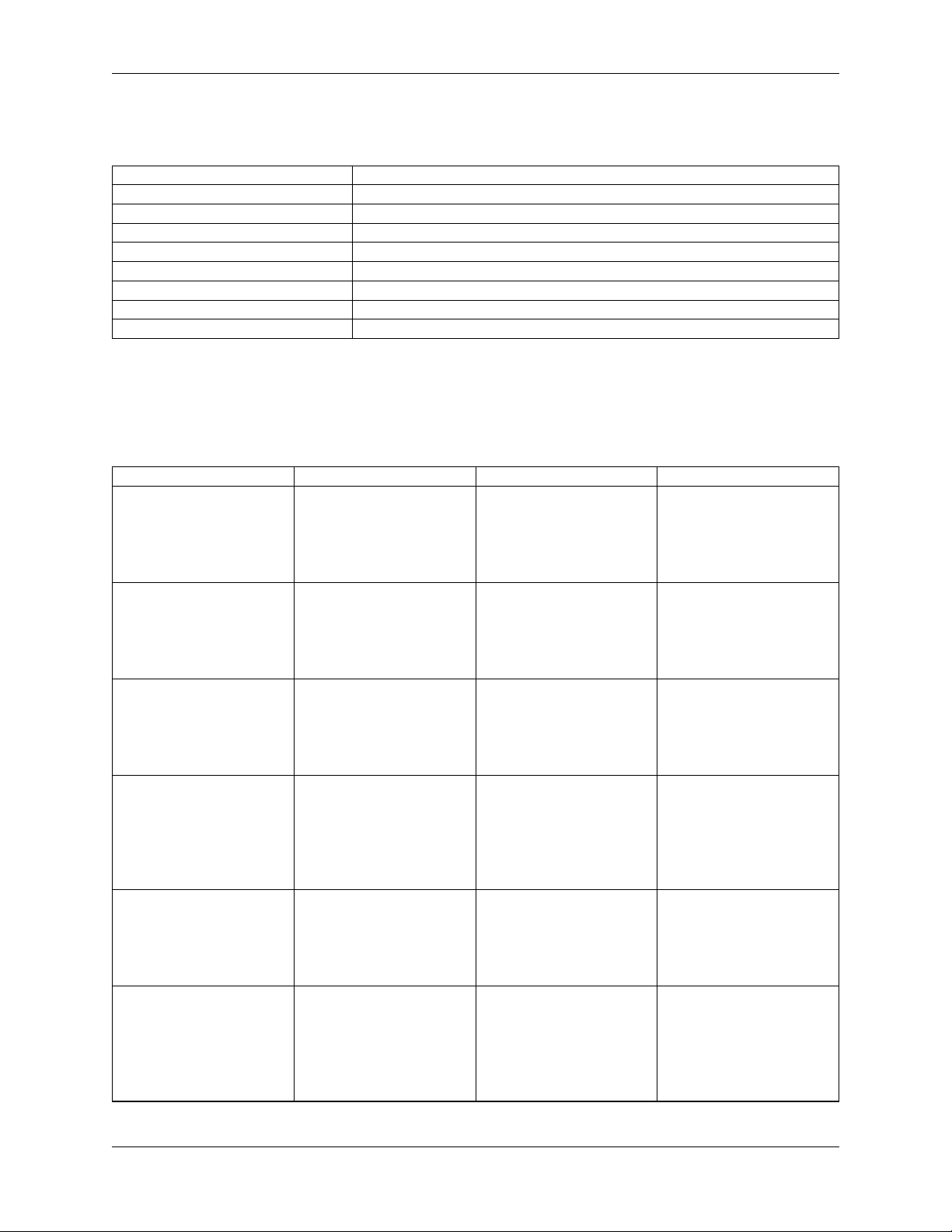
2.3.6 Physical Specifications
Power Level Rack Units Size Weight
5 kW 3U
5.25” H x 19” W x 24” D
(13.34 x 48.26 x 60.96
cm)
74 lbs (34.57 kg)
10 kW 3U
15 kW 3U
4U
20 kW
Models with 380/415 Vac
and 440/480 Vac, 3Φ
input
6U
20 kW
Models with 208/240 Vac,
3Φ input
4U
25 kW
Models with 380/415 Vac
and 440/480 Vac, 3Φ
input
94 lbs (42.64 kg)
5.25” H x 19” W x 24” D
(13.34 x 48.26 x 60.96
cm)
125 lbs (56.70 kg)
5.25” H x 19” W x 24” D
(13.34 x 48.26 x 60.96
cm)
160 lbs (72.6 kg)
7” H x 19” W x 24” D
(17.8 x 48.2 x 60.9 cm)
185 lbs (83.9 kg)
10.5” H x 19” W x 24” D
(26.67 x 48.26 x 60.96
cm)
180 lbs (81.7 kg)
7” H x 19” W x 24” D
(17.8 x 48.2 x 60.9 cm)
continues on next page
22 Chapter 2. Product Introduction
 Loading...