

Page 1
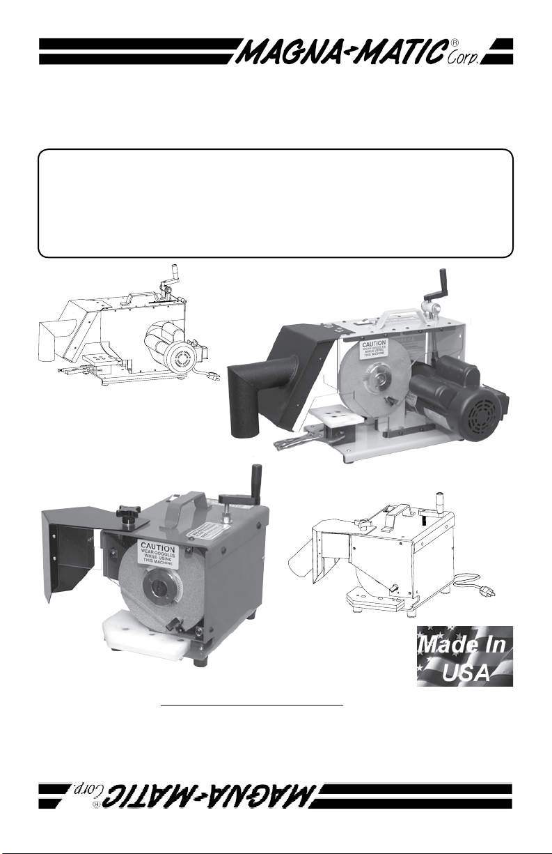
OPERATING INSTRUCTIONS
For Magna-Matic Sharpeners
Covering Models:
MAG-8000 Universal Lawn Mower Blade Sharpener
MAG-9000 Lawn Mower Blade Sharpener
Visit us at www.magna-matic.com for more photos
of products & other helpful info.
Helping you get the most
out of your shop for the last 40 years.
Page 2
page page
THE SAFE WAY IS THE
ONLY WAY TO GRIND!
Instructions given with this symbol are for personal safety. Be
sure you and your employees follow them. A careful operator
is the best insurance against accidents.
Before handling any equipment read and understand the
instructions.
When using electric tools, basic safety
precautions should always be followed to
WARNING
1. Grounding Instructions - This tool must be grounded
while in use to protect the operator from electric shock. The
tool is equipped with an approved three conductor cord and
three prong grounding type plug to t the proper grounding
type receptacle. The green (or green and yellow) wire is the
grounding wire.
2. Extension Cords - Use only three wire extension cords
which have three prong grounding type plugs and three pole
receptacles which accepts the tool’s plug. Replace or repair
damaged cords.
reduce the risk of re, electric shock, and
personal injury including the following.
3. Keep Work Area Clean - Cluttered areas and benches
invite accidents.
4. Consider Working Environment - Don’t use power tools
in damp or wet locations. Keep work area well lit. Don’t
expose power tools to rain. Do not use tool in presence of
ammable liquids or gases.
5. Keep Children Away - All visitors should be kept a safe
distance form the work area. Do not let visitors have contact
with the tool or the extension cord.
6. Store Idle Tools - When not in use, tools should be stored
in dry, high or locked-up places out of reach of children.
7. Don’t Force Tool - It will do the job better and safer at the
rate for which it was designed.
1
Page 3
8. Don’t Over-Reach - Keep proper footing and balance at all
times.
9. Wear Proper Apparel - Do not wear loose clothing or jewelry that can get caught in moving parts. Rubber gloves and
non-skid foot wear are recommended when working outdoors.
Wear protective hair covering to contain long hair.
10. Use Safety Glasses - Also face or dust mask-wrap
around goggles, or other eye protection.
11. Don’t Abuse Cord - Never carry tool by cord or yank it
to disconnect from receptacle. Keep cord from heat, oil, and
sharp edges.
12. Disconnect Tool - When not in use; before servicing;
when changing grinding wheel.
13. Avoid Accidental Starting - Don’t carry plugged in tool.
Be sure switch is off when plugging in.
14. Grinding Wheels - Use only grinding wheels having a
maximum operating speed of 5500 RPM. KEEP GUARDS IN
PLACE.
15. Guard Against Electrical Shock - Prevent body contact
with grounded surface. For example: pipes, radiators, etc.
16. Stay Alert - Watch what you are doing. Use common
sense. Do not operate tool when you are tired, or under the
inuence of any drugs or alcohol.
17. Check Damaged Parts - Before further use of the tool,
a guard or other part that is damaged should be carefully
checked to determine that it will operate properly and perform
its intended function. Check for alignment of moving parts,
breakage of parts, mounting and any other condition that effect
its operation. All parts should be properly repaired or replaced.
Do not use this tool if the switch does not turn it on or off.
18. Never Leave Tool Unattended - Turn the power off.
Don’t leave the tool until it comes to a complete stop.
19. Replace Cracked Wheels Immediately.
20. Read - the enclosed A Primer on Grinding Wheel
Safety (NORTON® Publication)
21. Never attach the provided spanner wrench ,arbor
wrench, or any other object to the grinder.
2
Page 4
page page
Model Descriptions
If you have further questions or do not understand any of the
instructions please contact us! We are happy to give any needed
extra explanation. Thank you for your purchase of MAGNAMATIC high-performance service tools.
MAG-8000 Universal Lawn Mower Blade Sharpener
The MAG-8000 is the latest technology in rotary lawn mower blade
sharpening. It holds 3 patents for its revolutionary design. Since its
release in 1999 the MAG-8000 has quickly become the standard in
the Outdoor Power Equipment Industry. The MAG-8000 is designed to
sharpen almost all lawn mower blades, conventional blades (straight
at cutting edges) and mulching blades (curved cutting edges.)
Instructions
begin on page 4
MAG-9000 Lawn Mower Blade Sharpener
The MAG-9000 is a solid low cost solution in rotary lawn mower blade
sharpening. It provides you with 60 second per blade sharpening per-
formance in a small package. Since its release in 1987 the MAG-9000
has become a best friend of lawn care professionals The MAG-9000 is
designed to be a compact sharpener for conventional blades (straight
at cutting edges).
Instructions begin
on page 16
3
Page 5
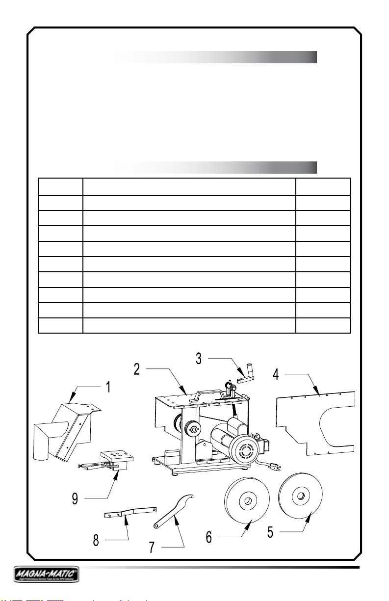
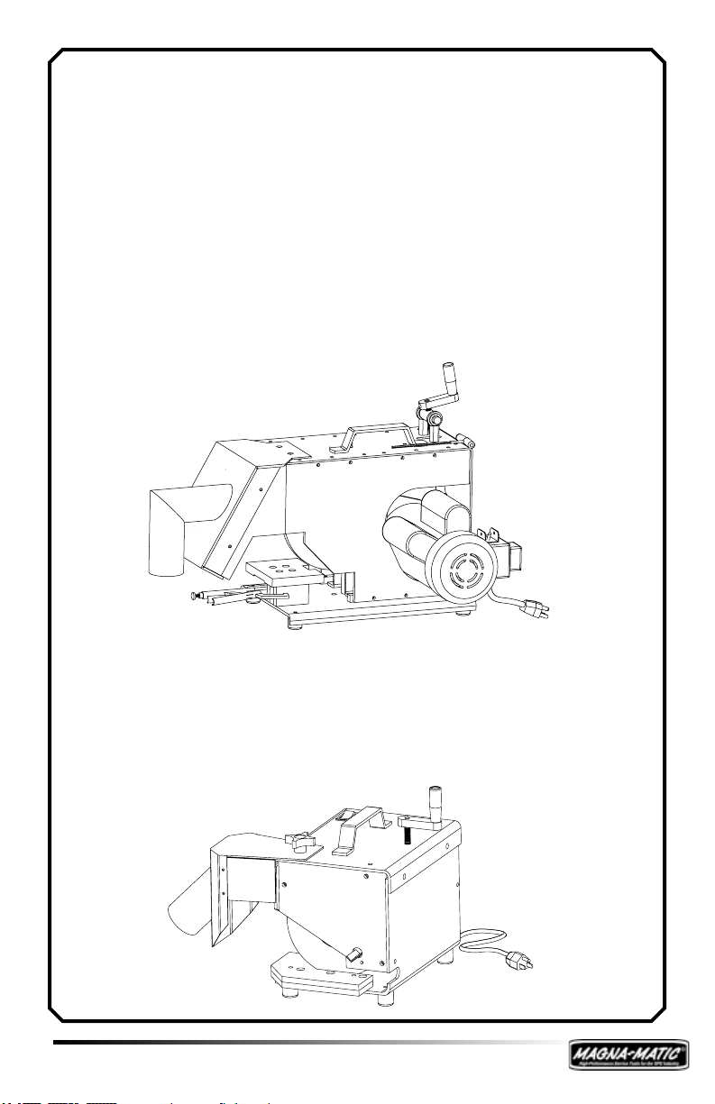
Begin The Assembly
Step 1: MAG-8000
Unpack the MAG-8000, please keep the box and packaging incase of shipping damage or any need for return. When
unpacking the MAG-8000 take stock of all the items in the box.
Parts Inventory
Qty Description Key #
1 Grit Guard 1
1 Sharpener Body 2
1 Crank Handle 3
1 Motor Side Lexan® Guard 4
1 Grinding Wheel (1/2” wide) 5
1 Grinding Wheels (1” wide) 6
1 Arbor Wrench 7
1 Spanner Wrench 8
1 Mobile Work Table 9
4
Page 6
page page
MAG-8000 Assembly
Step 2:
First remove the TRANSPORT BRACKET from the
MAG-8000 arbor, keep
the transport bracket
for any future shipping
needs. You will need to
remove the black bolting bar to allow clearance for the transport
bracket to be removed.
Use the spanner wrench
if needed to remove the
arbor nut. Assemble the
crank handle, align the
set screw to the milled
at on the threaded adjustment rod, and use the Bondhus 1/8”
wrench to tighten the set screw.
Step 3:
Mount a grinding
wheel to the MAG-
8000 arbor. One inch
wide wheels are best
used with conventional
lawn mower blades,
and the half-inch wide
wheels are required
for mulching blades.
NOTE: when mounting
the half-inch grind-
ing wheel the ARBOR
SPACER is required.
The ARBOR SPACER is
NOT required for 1 inch wide wheels. See above diagram.
5
Page 7
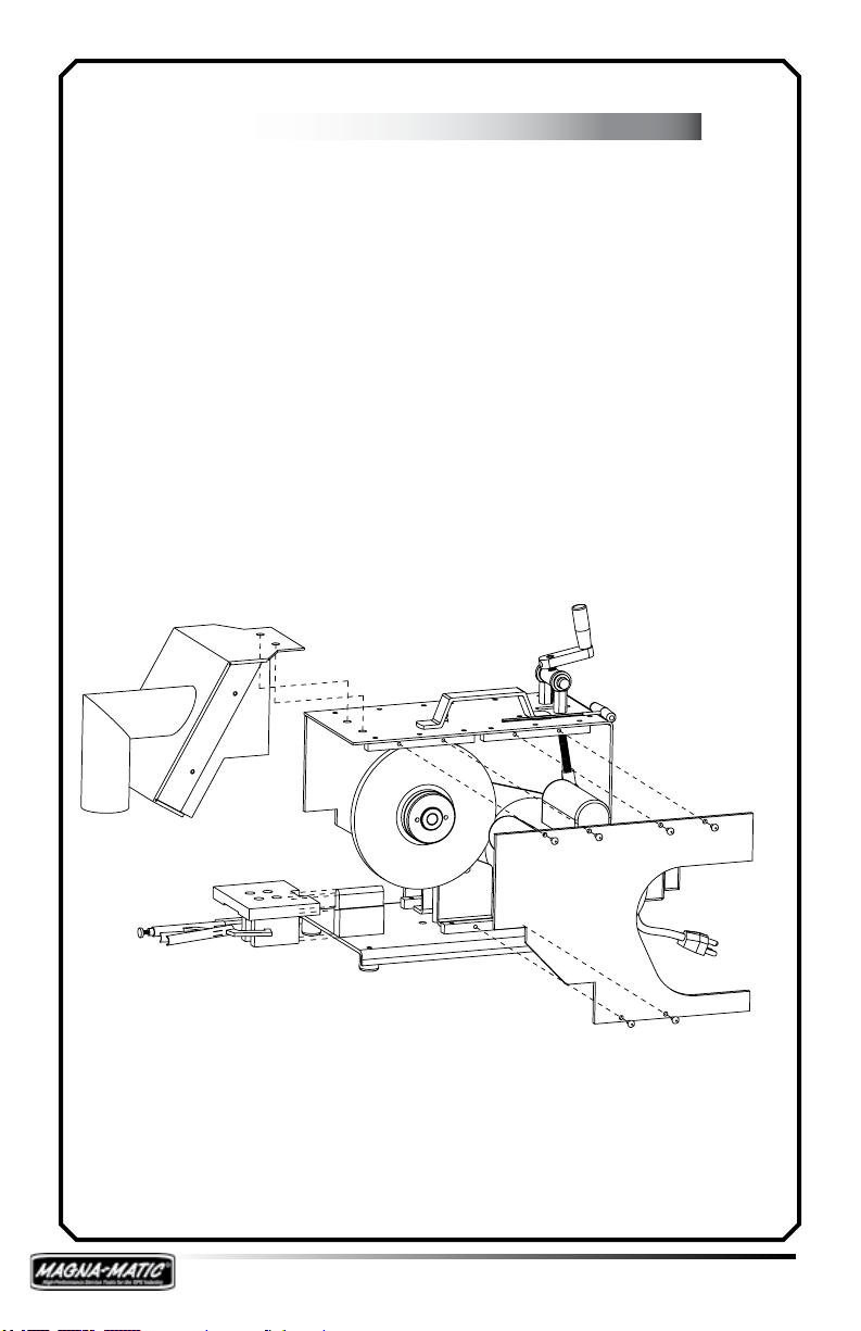
MAG-8000 Assembly Con’t
Step 4:
Assemble the grit guard to the MAG-8000 using the bolts found
on the grit guard. Do not tighten the Lexan® windows on the
grit guard (they will be tightened in a later step).
Assemble Motor Side Lexan® Guard to the MAG-8000. The
motor side Lexan® guard will slide behind the grit guard
Lexan® window - slide it forward to clear the motor capacitors
- then align the holes and fasten the guard to the bolting bars.
Raising or lowering the motor with the angle adjustment crank
will provide more clearance. Use the hardware in the holes and
the Bondhus T-handle wrench. Be sure to tighten 3 bolts under
the MAG-8000, and the 6 along the top to secure the bolting
bars holding the Lexan® guard. Lastly tighten the grit guard’s
Lexan® windows.
Step 5:
Testing the unit, be sure the grinding wheel moves freely.
Ensure the MAG-8000 ON/OFF switch is in the OFF POSITION,
plug the MAG-8000 into a 20 amp, 110 volt outlet. Switch the
ON/OFF switch to the ON POSITION to test the motor. The
motor should achieve FULL speed in 1-2 seconds. If it does
not, see page 13, or contact MAGNA-MATIC (800-328-1110).
6
Page 8
page page
MAG-8000 Use
Step 6: Mulching Blades
Be sure to wear protective clothing before handling and
sharpening lawn mower blades. Wear safety glasses and
protective gloves.
Blade & Sharpener Preparation
1. Clean the blade to its base material, using the MAG-12000
blade cleaner, or alternate cleaning process.
2. Check the straightness with the gauge rod of the MAG1000 blade balancer. (Never straighten bent blades!)
3. Obtain a balance reading from the MAG-1000 to indicate the
light end of the lawn mower blade. Once the light end
is sharpened, it is complete. The heavy end is used to
remove material for balance. SEE MAG-1000 Instruction
Manual for more info on blade balancing.
4. The MAG-8000 will require the 1/2” inch wide grinding wheel
to sharpen a mulching blade. Mount the 1/2” wide grinding wheel on the MAG-8000. (Arbor spacer req.)
5. The xed 1/2” wide curved metal work table will be needed
to sharpen a mulching blade, remove the clamp-able mo-
bile work table.
6. Lower the grinding wheel with the adjustment crank, stop
just before you grind the corner of the work table. When
the grinding wheel is almost touching the corner of the
work table (curved or mobile work tables) you will produce
a 30 degree angle on the lawn mower blade. (see page 8)
Mulching Blade Sharpening
7. Switch the ON/OFF switch to the ON position.
8. Place the mulching blade in the MAG-8000 starting at
the inside of the edge (closest to the mounting hole), and
pull the blade across the grinding wheel (perpendicular to
the rotation of the grinding wheel, see page 10.) Keep
rm pressure downward on the blade to maintain contact
with the rounded surface of the work table. Allow the
work table to follow the contours of the mulching blade.
Take one pass at a time. Use even pressure into the
grinding wheel to achieve an even stream of sparks.
7
Page 9
MAG-8000 Use Con’t
Step 6: Con’t
9. When using the MAG-8000 for mulching blades keep the
blade level, and perpendicular to the rotation of the grind-
ing wheel. Pay close attention to the TIP of the blade, see
page 25.
This view of the MAG-8000
(with the grit guard removed
for visibility) you are able
to see how the curved edge
mulching blade should follow
over the rounded work table.
Contact between the blade
and work table must be maintained
Adjusting the Edge Angle
Applies to both MAG-8000 and MAG-9000
30 Degree Reference Point - When the grinding wheel
is lowered to the work table (almost cutting the work table
corner) you will produce a 30 degree angle on the lawn mower
blade. As the grinding wheel wears and reduces in diameter,
continue to lower the grinding wheel to almost touch the work
table to maintain a consistent 30 degree edge angle on a blade.
The edge angle can be varied plus or minus the 30 degree
reference point via the adjusting crank. Lowering the grinding wheel into the work table (grinding into the work table)
will result in a greater than 30 degree angle (a steeper angle.)
Note, you will be creating a new angle reference point Raising
the grinding wheel will result in a lesser than 30 degree angle
(a more shallow angle.)
8
Page 10

page page
MAG-8000 Use Con’t
Step 7: Conventional Blades
Blade & Sharpener Preparation
1. Clean the blade to its base material, using the MAG-
12000 blade cleaner, or alternate cleaning process.
2. Check the straightness with the gauge rod of the MAG-1000
blade balancer. (Never straighten bent blades!)
3. Obtain a balance reading from the MAG-1000 to indicate the
light end of the lawn mower blade. Once the light end
is sharpened, it is complete. The heavy end is used to
remove material for balance. SEE MAG-1000 Instruction
Manual for more info on blade balancing.
4. The MAG-8000 will require the 1” inch wide grinding wheel
to sharpen a conventional blade. Mount the 1” wide grinding wheel on the MAG-8000. (1/2” wide grinding wheel
may be used for conventional blades)
5. The mobile work table will be needed to sharpen a conventional blade, slide the mobile work table over the curved
1/2” wide work table, and clamp it tight with the attached
vice grip.
6. Lower the grinding wheel with the adjustment crank, stop
just before you grind the corner of the work table. When
the grinding wheel is almost touching the corner of the
work table (curved or mobile work tables) you will produce
a 30 degree angle on the lawn mower blade. (see page 8)
7. Place the conventional blade on the at work table and pull
and push the blade across the grinding wheel (perpendicular to the rotation of the grinding wheel, see page 10.)
Keep rm pressure downward on the blade to maintain
contact with the surface of the work table. The force into
the grinding wheel should be substantial, resulting in a
continuous stream of sparks from the grinding wheel. The
grinding process should be continuous without interruption
until nished. Pay close attention to the TIP of the blade,
see page 25.
9
Page 11

The above diagram shows the application of movement and
force to the blade during sharpening a conventional blade. Note,
for curved edge mulching blades, it is the same except for the
“forth” or inward fed motion. You will maintain much more control if you only “pull” mulching blades through the MAG-8000. It
is critical with both blade types that the operator keeps downward pressure “force” on the blade, this will prevent chattering
and keep the grinding wheel “true” or round.
Overhead view of blade
approach - applies to both conven-
tional and curved edge mulching
blades.
10
Page 12

page page
MAG-8000 Wheel Replacement
Be sure the MAG-8000 is unplugged. Using a 1/8” Allen
wrench (supplied with MAG-8000) remove the (6) screws of the
front Lexan® guard. Locate your spanner wrench and arbor
wrench (both supplied by Magna-Matic.) The arbor wrench ts
into a square notch in the arbor, behind the grinding wheel, and
the spanner wrench ts into the two holes in the arbor nut. See
diagrams below.
Always inspect grinding wheels for possible damage - never
mount a cracked grinding wheel.
For optimum performance use only grinding wheels specied
by Magna-Matic. All NORTON® brand grinding wheels sold by
Magna-Matic are speed tested for 5500 RPM
NOTE: Arbor has LEFT HANDED THREADS.
MAG-8000 OEM WHEEL = 9000-35RP &
8000-30RP
11
Page 13

MAG-8000 Care & Service
General Care:
Keep the MAG-8000 clean, use compressed air to blow the
machine off periodically. Use mild soapy water to clean powder
coated surfaces and Lexan® guards.
Greasing of Bearing Blocks:
Care should be taken when re-greasing bearings to avoid overlling. Overlling can lead to excessive heat and or unseating
of the seals. Grease should be introduced in small increments
and under light pressure. The use of pneumatic greasing is not
recommended unless low pressure is assured. Whenever possible, the shaft should be rotated during re-lubrication to insure
proper grease distribution throughout the raceways.
3-6 Months OR 500-1000 Machine Hours - Fill with 2 grams.
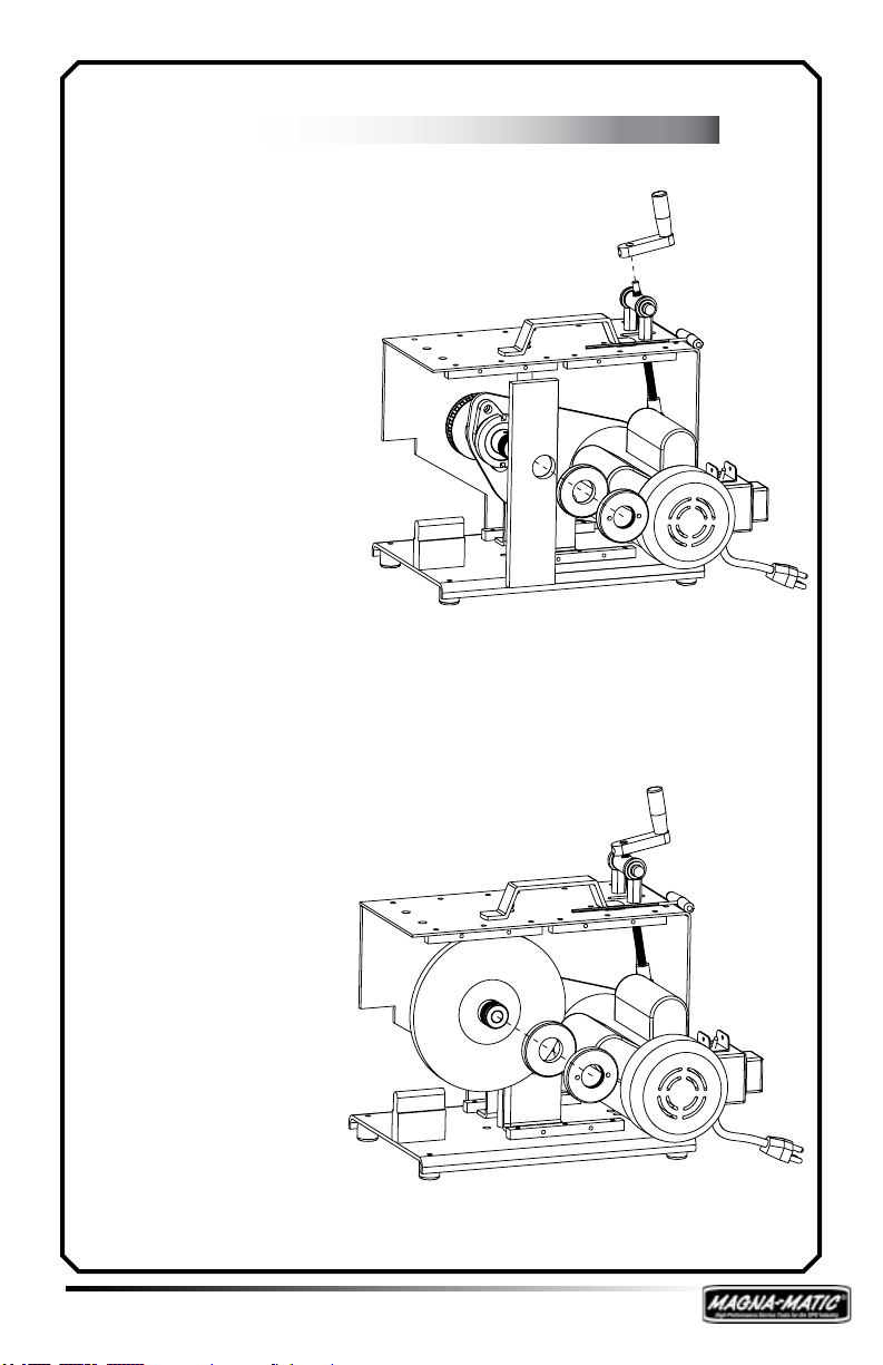
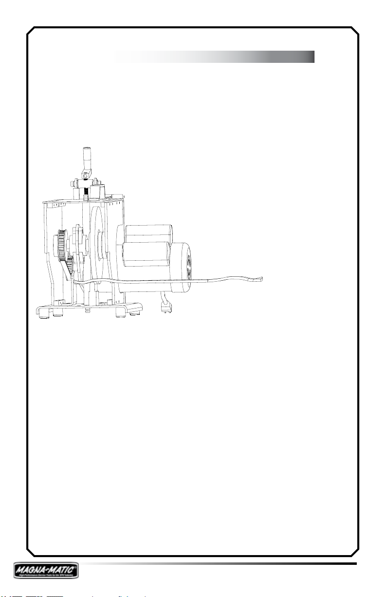
Timing Belt Replacement
See the diagram to the right
for proper belt tension. Tension can be applied either
at the bolts of the motor
or bearing blocks. There is
slight play in the holes to
apply or relieve belt tension.
Angle Adjustment Timing
When replacing the adjustment trunnion allow one inch
of space from the top of the
threaded rod to the top of the
trunnion. When replacing the
yoke, the threaded rod should
be ush with the end of the
threads of the yoke before con-
necting to the pivot plate.
12
Page 14

page page
MAG-8000 Trouble-Shooting
The MAG-8000 will not start.
Double check that the MAG-8000 is plugged in a 20 amp (minimum) circuit. Due to the “instant starting” of the MAG-8000 it
has a tremendous starting draw, therefore a minimum 20 amp
circuit is required.
Check all building fuses or circuit breakers.
To diagnose a ON/OFF switch problem, (unplug from power
source.) Open the square access panel below the switch, and
disconnect the (2) wires from the switch (label the wires before
disconnecting.) Directly connect and insulate the (2) wires.
Plug the MAG-8000 into a power source, this should start the
motor without the switch.
If the MAG-9000 still does not start after this test, the solid
state switch, capacitors, or the motor is no longer function-
ing and must be replaced. Call 800-328-1110 for replacement
parts or a warranty issue.
The MAG-8000 is vibrating.
This is caused by a grinding wheel that is “out-of-round” or
“out-of-balance” - this will happen when the user does not
apply downward pressure on the blade when sliding it back and
forth in the MAG-8000. Also, on occasion, grinding wheels can
have a “hard spot” which will also cause this.
To repair the wheel you can dress it with a grinding wheel
dressing tool, or you can use an old lawn mower blade. When
using the old lawn mower blade nd a portion of the blade
that is square stock (near the mounting hole - not on an edge)
and grind it with the MAG-8000, but do not go back and forth
- simply keep pressure down on the work table and into the
wheel evenly. This will re-shape the wheel back into a circle.
The MAG-8000 belt is not tight (or making excessive
noise.)
See page 12 on how to re-tension the belt. Also note having
the blade extremely tight will create a high pitched noise, and
signicantly reduce the life of the belt.
13
Page 15

MAG-8000 Specications
MAG-8000 MAG-8000 (Euro)
Length 24 inches 60.9 cm
Width 12 inches 30.5 cm
Height 17 inches 43.1 cm
Weight 80 LBS 36 kg
Ship Weight 1 box 85 LBS 38 kg
Motor Specs BALDOR® ELECTRIC BALDOR® ELECTRIC
Horse Power 1 1
RPM 3450 2850
Duty Cycle Continuous Continuous
Hertz 60 50
Volts 115 220
Phase Single Single
Capacitors Dual (2) Dual (2)
Solid State Switch Yes Yes
Motor Type Industrial - Totally
Insulation Class F Class F
Direction Single Direction Single Direction
Fan Cooled Yes Yes
Transmission Timing belt/pulley Timing belt/pulley
Grinding Wheels NORTON® Abrasives NORTON® Abrasives
Wheel Dimensions
Enclosed
7” dia x 1” thick x 1-1/4”
dia arbor
7” dia x 1/2” thick x 11/4” dia arbor
Industrial - Totally
Enclosed
17.7 cm dia x 2.5 cm
thick x 3.18 cm dia
arbor
17.7 cm dia x 1.27 cm
thick x 3.18 cm dia arbor
14
Page 16

page page
15
Page 17

Begin The Assembly
Step 1: MAG-9000
Unpack the MAG-9000, please keep the box and packaging
incase of shipping damage or any need for return. When un-
packing the MAG-9000 take stock of all the items in the box.
Parts Inventory
Qty Description Key #
1 Grit Guard 1
1 Sharpener Body 2
1 Spanner Wrench 3
1 Arbor Wrench 4
16
Page 18

page page
MAG-9000 Assembly
Step 2:
First assemble the grit guard to the MAG-9000 body using the
plastic knob located on the top of the MAG-9000.
Step 3:
Be sure the MAG-9000 is unplugged, and adjust the angle
adjustment crank to make sure the grinding wheel freely
rotates. SEE PAGE 8 for information on EDGE ANGLE ADJUST-
MENT
17
Page 19

MAG-9000 Use
Step 4: Conventional Blades
Be sure to wear protective clothing before handling and sharpening lawn mower blades. Wear safety glasses and protective
gloves.
Blade & Sharpener Preparation
1. Clean the blade to its base material, using the MAG-12000
blade cleaner, or alternate cleaning process.
2. Check the straightness with the gauge rod of the MAG-1000
blade balancer. (Never straighten bent blades!)
3. Obtain a balance reading from the MAG-1000 to indicate the
light end of the lawn mower blade. Once the light end
is sharpened, it is complete. The heavy end is used to
remove material for balance. SEE MAG-1000 Instruction
Manual for more info on blade balancing.
4. Lower the grinding wheel with the adjustment crank, stop
just before you grind the corner of the work table. When
the grinding wheel is almost touching the corner of the
work table you will produce a 30 degree angle on the lawn
mower blade. (see page 8)
The above diagram shows left and
right-handed blade approach into the
MAG-9000. The blade must stay parallel to the 45 degree angle cut in the
work table.
18
Page 20

page page
MAG-9000 Use
Step 4: Conventional Blades
Conventional Blade Sharpening
7. Switch the ON/OFF switch to the ON position.
8. Place the conventional blade on the at work table and pull
and push the blade across the grinding wheel. Keep rm
pressure downward on the blade to maintain contact with
the surface of the work table. The force into the grinding wheel should be substantial, resulting in a continuous
stream of sparks from the grinding wheel. The grinding
process should be continuous without interruption, until
nished. Take extra care when near the TIP of the blade,
it is critical that the TIP does not become rounded. SEE
PAGE 25 TIP GEOMETRY. Note: the grinding wheel will
dress to a 45 degree angle - this is normal and intended.
19
Page 21

MAG-9000 Wheel Replacement
Be sure the MAG-9000 is unplugged. Using a 5/32” Allen
wrench remove the (3) screws of the front Lexan® guard.
Locate your spanner wrench and arbor wrench (both supplied
by Magna-Matic.) The arbor wrench ts into a square notch in
the arbor, behind the grinding wheel, and the spanner wrench
ts into the two holes in the arbor nut. See diagrams below.
Always inspect grinding wheels for possible damage - never
mount a cracked grinding wheel.
For optimum performance use only grinding wheels specied
by Magna-Matic. All NORTON® brand grinding wheels sold by
Magna-Matic are speed tested for 5500 RPM
NOTE: Arbor has LEFT HANDED THREADS.
MAG-9000 OEM WHEEL = 9000-23RP
20
Page 22

page page
MAG-9000 Trouble-Shooting
The MAG-9000 will not start.
Double check that the MAG-9000 is plugged in a 15 amp (minimum) circuit.
Check all building fuses or circuit breakers.
First determine what type of switch your MAG-9000 has.
(1987 - 1996 metal toggle switch)
(1997 - 2005 plastic lit rocker switch)
(2006 - present metal toggle switch)
To diagnose a ON/OFF switch problem, (unplug from power
source) remove the back screen cover. Disconnect the (2)
black wires, one from the motor and one from the cord set.
Directly connect and insulate the (2) black wires. Plug the
MAG-9000 into a power source, this should start the motor
without the switch. The third “red or blue” wire is only for the
switch’s light [MAG-9000 sharpeners with the metal toggle
switch do not have this wire because there is no light.]
If the MAG-9000 still does not start after this test, the capacitor or the motor is no longer functioning and must be replaced.
(SEE WIRING DIAGRAM PAGE 22)
Call 800-328-1110 for replacement parts or a warranty issue.
The MAG-9000 is vibrating.
This is caused by a grinding wheel that is “out-of-round” or
“out-of-balance” - this will happen when the operator does not
apply downward pressure on the blade when sliding it back and
forth in the MAG-9000. Also, on occasion, grinding wheels can
have a “hard spot” which will also cause this.
To repair the wheel you can dress it with a grinding wheel
dressing tool, or you can use an old lawn mower blade. When
using the old lawn mower blade nd a portion of the blade
that is square stock (near the mounting hole - not on an edge)
and grind it with the MAG-9000, but do not go back and forth
- simply keep pressure down on the work table and into the
wheel evenly. This re-shape the wheel back into a circle
21
Page 23

MAG-9000 Trouble Shooting
22
Page 24

page page
MAG-9000 Specications
MAG-9000 MAG-9000 (Euro)
Length 12 inches 30.5 cm
Width 8 inches 20.3 cm
Height 8 inches 20.3 cm
Weight 45 LBS 20 kg
Ship Weight 1 box 48 LBS 22 kg
Motor Specs LEESON® ELECTRIC LEESON® ELECTRIC
Horse Power 1/2 1/2
RPM 3450 2850
Duty Cycle Std / Intermittent Std / Intermittent
Hertz 60 50
Volts 115 220
Phase Single Single
Capacitors Single (1) Single (1)
Solid State Switch No No
Thermal Protection Yes Yes
Motor Type Industrial - Totally
Enclosed
Insulation Class F Class F
Direction Single Direction Single Direction
Fan Cooled Yes Yes
Transmission Direct Drive Direct Drive
Grinding Wheels NORTON® Abrasives NORTON® Abrasives
Wheel Dimensions 7” dia x 1” thick x 1-
1/4” dia arbor
Industrial - Totally
Enclosed
17.7 cm dia x 2.5 cm
thick x 3.18 cm
23
Page 25

24
Page 26

page page
Rotary Mower Blade Tip Geometry
Consider the following if you sharpen rotary lawn
mower blades.
The tip of the blade
does the majority
of the cutting. To
produce a tip, three
reliefs are necessary.
Think of a lawn
mower blade as a
circular saw with
only “TWO TEETH”
and remember the
tip does the majority
of the cutting work.
Repetitive observa-
tion of worn cutting
edges shows that
the rst one inch
does the majority of
the cutting work.
IMPORTANT
NOTES:
Attempting to
straighten a lawn
mower blade may
cause fractures in
the hardened steel
of the blade and
shall be avoided.
Anytime you alter
the steel of the
blade due to resharpening, wear or
build-up, you change
the balance.
Description Diagram
Relief 1:
Top View - built
into the blade.
(generally 2-5
degrees)
Relief 2:
End View - To be
re-sharpened.
(generally 60
degrees)
1
Generally 0˚
Relief 3:
End View - built
into the blade.
Top View:
Worn Blade
Edge
Worn away bottom
surface at tip, as
shown, is a sign
of poor blade
maintenance. The
blade will tear the
grass, resulting
in a poor looking
lawn.
Optimum
3
NOT ACCEPTABLE
2
25
Page 27

Key Description
A Trailing edge of the cutting edge face
B Mounting hole
C Leading edge of the cutting edge face
D Lift
E Cutting edge face
F Cutting edge angle (30˚ shown)
G Blade cutting tip (or tooth)
H Overall cutting diameter
Anatomy of a
Lawn Mower
Blade
Use this diagram when asking questions
to Magna-Matic representatives, or as it is
referenced in this manual.
26
Page 28

WARRANTY
This warranty is extended only to MAGNA-MATIC’s commercial customers. To protect the quality of this tool, every
step in its manufacture has been carefully controlled. It is
constructed of only the nest materials by skilled craftsmen who take pride in their work. MAGNA-MATIC CORP.
warrants the tools manufactured and/or repaired to be
free of defects in material and workmanship for a period
of 365 days after purchase. Any tool or part proved to
MAGNA-MATIC’s satisfaction to be defective during that
period will be repaired or replaced at MAGNA-MATIC’s
option if returned prepaid. MAGNA-MATIC’s sole obligation and your exclusive remedy under this warranty shall
be limited to such repair or replacement. In no event shall
MAGNA-MATIC be liable for any consequential or incidental
damages. This warranty does not apply to parts (motor
& grinding wheel) not manufactured by MAGNA-MATIC or
failing due to ordinary wear, subjected to abuse, accidental
damage, improper operations, maintenance or repair, or to
other damage by circumstances beyond MAGNA-MATIC’s
control.
This warranty is exclusive and in lieu of all other expressed
or implied warranties including without limitation, the
implied warranties of merchantability and tness for a particular purpose.
Magna-Matic Corporation
W4599 County Road IW
Waldo WI 53093
USA
Phone: (920) 564-2366
FAX: (920) 564-2368
Toll Free USA & Canada
1-800-328-1110
© 2002-2006 Magna-Matic Corporation, all rights reserved.
http://www.magna-matic.com
sales@magna-matic.com
 Loading...