

Page 1

Operating Manual
Universal WE TOUCH with TCODE
Multi-Directional Magnetic Wet Bench
Part number 022690
Page 2

UNIVERSAL WE TOUCH TCODE
2 / 85 MX UWETOUCH_v.3
2019-05-03
Page 3
UNIVERSAL WE TOUCH TCODE (600/900) v.3 Identification
MX UWETOUCH_v.3 3 / 85
2019-05-03
Identification
Machine data
Manufacturer
MAGNAFLUX GmbH
Machine type
UNIVERSAL WE TOUCH TCODE (600/900) v.3
Machine number
…
Customer
…
Country of application
…
Order
…
Year of manufacture
2019
Document
Document No.:
MX UWETOUCH_v.3
Version:
3
Issue date:
2019-05-03
© Copyright 1934-2019
MAGNAFLUX GmbH
All rights reserved. Reprinting, even in part,
only permitted with the approval of MAGNAFLUX
GmbH.
Manufacturer
MAGNAFLUX GmbH
Bahnhofstrasse 94-98
73457 Essingen
Germany
P: +49 7365 81-0
F: +49 7365 81-449
www.eu.magnaflux.com
Page 4
Structure of these operating instructions UNIVERSAL WE TOUCH TCODE (600/900) v.3
4 / 85 MX UWETOUCH_v.3
2019-05-03
Structure of these operating instructions
Chapter 1
Information for your safety
starting page 9
Chapter 2
Machine description
starting page 17
Operation and application
Chapter 3
Basis of operation
starting page 36
Chapter 4
Machine adjustments
starting page 53
Chapter 5
Workpiece testing
starting page 60
Chapter 6
Conduct during malfunctions
starting page 64
Chapter 7
Machine cleaning
starting page 65
Chapter 8
Machine maintenance
starting page 66
Supplementary instructions and information
Chapter 9
Machine transport
starting page 76
Chapter 10
Setting up the machine and commissioning it
starting page 80
Chapter 11
Take the machine out of operation and disposing of it
starting page 84
Page 5
UNIVERSAL WE TOUCH TCODE (600/900) v.3 Machine equipment
MX UWETOUCH_v.3 5 / 85
2019-05-03
Machine equipment
Individual limits of the machine
Workpiece length
70-600/900 mm (3”-23”/35”)
Workpiece diameter
max. 300 mm (11.8”)
Weight of the workpieces
max. 100 kg (220 lbs)
Activation cycle
Relative ED 60%, absolute ED max.30 s
ON/ 20 s OFF at 50% of nominal power
Power input
approx. 59/69 kVA
Magnetising
X
Magnetising circuit 1
max. 2000 A AC (effective value)
max. 3000 A AC (effective value) as
option
X
Magnetising circuit 2
max. 15.000 AW (amp-turns) AC
(effective value)
Magnetising circuit 1
Magnetising the circuit by axial current
flow or field current flow with inserted
or attached conductor at sleeve 1
Magnetising circuit 2
Longitudinal magnetising by yoke
(coil) magnetising
Spraying
X
Hand-held hose
-
Hand-held shower with push button (option)
-
Large-area shower or spray nozzles/shower heads (option)
-
Nozzles in the 5agnetizing coil (option)
UV lighting
-
UV hand-held lamp
Model: Magnaflux EV6000 (option)
-
UV panel lamp
Model: Magnaflux UV-LED 365-30
(option)
-
UV panel lamp
Model: Magnaflux ST700 (option)
Special equipment
-
Two-handed control (option)
X
Control panel with touch operation
-
T-Code Parameter Memory (option)
-
Dark booth (option)
Page 6

Table of contents UNIVERSAL WE TOUCH TCODE (600/900) v.3
6 / 85 MX UWETOUCH_v.3
2019-05-03
Table of contents
1 General safety instructions ............................................................................... 9
1.1 Operating Manual ..................................................................................................... 9
1.2 Hazards when handling the machine ...................................................................... 12
1.3 Emergency measures ............................................................................................. 12
1.4 Magnetic loads at the workplace ............................................................................ 13
1.5 Mechanical hazards caused by driven machine parts ............................................ 14
1.6 Risk of crushing due to heavy workpieces.............................................................. 14
1.7 Skin irritation caused by test substances................................................................ 14
1.8 High fire risk due to oily test liquids ........................................................................ 15
1.9 Obligations of the operating company .................................................................... 15
1.10 Defective protective and safety features................................................................. 16
1.11 Alterations or modifications ..................................................................................... 16
1.12 Spare/ wear parts and consumables ...................................................................... 16
2 Machine description ........................................................................................ 17
2.1 Intended use ........................................................................................................... 17
2.1.1 Specification of the workpieces .................................................................... 18
2.1.2 Limits of the machine .................................................................................... 18
2.2 Structure of the machine ......................................................................................... 19
2.3 Safety equipment .................................................................................................... 20
2.4 Technical data ......................................................................................................... 21
2.4.1 Dimensions and weights ............................................................................... 21
2.4.2 Electrical data ............................................................................................... 21
2.4.3 Magnetising circuits ...................................................................................... 22
2.4.4 Clamping devices for the workpiece ............................................................. 23
2.4.5 Workpiece holders ........................................................................................ 23
2.4.6 Pneumatics ................................................................................................... 23
2.4.7 Test liquid system ......................................................................................... 23
2.4.8 UV-LED lamp (sample) ................................................................................. 24
2.4.9 Ambient conditions ....................................................................................... 24
2.4.10 Emissions ..................................................................................................... 24
2.5 Operator work stations ............................................................................................ 25
2.6 Markings and type plate on the machine ................................................................ 25
2.7 Testing liquid system and spraying of the workpiece ............................................. 26
2.8 Pneumatic Maintenance Unit .................................................................................. 29
2.9 Individual test sequence ......................................................................................... 30
2.10 Home position of the machine ................................................................................ 30
2.11 Magnetising the workpiece ..................................................................................... 31
2.11.1 Constant current control ............................................................................... 31
2.11.2 Current flow monitoring ................................................................................ 31
2.11.3 Magnetising types in accordance with EN ISO 9934-1 ................................ 32
2.11.4 Demagnetising of workpieces....................................................................... 33
2.12 Lighting on the workstation ..................................................................................... 34
2.13 Visual inspection ..................................................................................................... 35
3 Basis of operation ........................................................................................... 36
3.1 Option: Two-handed operation ............................................................................... 36
3.2 Pedal switch ............................................................................................................ 36
3.3 Touch control panel on the main control panel ....................................................... 37
3.3.1 Screen layout ................................................................................................ 37
3.3.2 Automatic mode ............................................................................................ 38
3.3.3 Automatic T-Code mode ............................................................................... 40
3.3.4 “Edit T-Code” screen .................................................................................... 42
3.3.5 Manual operation mode ................................................................................ 43
3.3.6 “Options” screen ........................................................................................... 45
3.3.7 Screen “User Administration” ....................................................................... 48
3.3.8 “Commissioning (IBN)” screen ..................................................................... 49
3.4 Switching the machine ON and OFF ...................................................................... 50
Page 7

UNIVERSAL WE TOUCH TCODE (600/900) v.3 Table of contents
MX UWETOUCH_v.3 7 / 85
2019-05-03
3.4.1 Emergency shut-down .................................................................................. 50
3.4.2 Before switching the machine ON ................................................................ 50
3.4.3 Switching the machine ON ........................................................................... 50
3.4.4 Reactivating the machine after an emergency stop ..................................... 51
3.4.5 Switching off the machine ............................................................................. 51
3.5 Select operating mode ............................................................................................ 52
4 Machine adjustments ...................................................................................... 53
4.1 Filling the test liquid tank ......................................................................................... 53
4.2 Overview of setting tasks ........................................................................................ 53
4.3 Set the distance between the sleeves .................................................................... 53
4.4 Replacing the magnetising mandrel (central conductor) ........................................ 55
4.5 Setting the magnetising parameters ....................................................................... 57
4.6 Manage users.......................................................................................................... 59
5 Inspecting workpieces .................................................................................... 60
5.1 Safety instructions ................................................................................................... 60
5.2 Testing the workpiece in automatic mode ............................................................... 61
5.3 Manual mode........................................................................................................... 62
5.4 Replacing the test liquid .......................................................................................... 63
6 What to do in the event of a fault .................................................................... 64
7 Machine cleaning ............................................................................................. 65
7.1 Clean the magnetising station ................................................................................. 65
7.2 Clean the test liquid tank ......................................................................................... 65
8 Maintenance ..................................................................................................... 66
8.1 Maintenance schedule ............................................................................................ 66
8.2 Inspection instructions ............................................................................................. 68
8.2.1 Where available: Checking the EMERGENCY STOP button ....................... 68
8.2.2 Where available: Checking the two-handed control ..................................... 68
8.2.3 Measuring the magnetising field strength ..................................................... 69
8.2.4 Magnetising testing ....................................................................................... 70
8.2.5 Checking the test liquid concentration .......................................................... 71
8.2.6 Verifying the test liquid indication capability ................................................. 72
8.2.7 Checking the UV Intensity ............................................................................ 73
8.3 Maintenance instructions ........................................................................................ 74
8.3.1 Drain the compressed air water separator.................................................... 74
8.3.2 Filling oil into the dosing oiler ........................................................................ 74
8.3.3 Cleaning the magnetising contacts ............................................................... 75
8.3.4 Cleaning the contacts of the high-current connections ................................. 75
9 Machine transport ............................................................................................ 76
9.1 Transport preparation .............................................................................................. 76
9.2 Transport in original packaging ............................................................................... 76
9.3 Unpacking the machine ........................................................................................... 77
9.4 Machine transport ................................................................................................... 77
9.4.1 Transporting the magnetising station with a forklift ...................................... 78
9.4.2 Transporting the magnetising station with a crane ....................................... 79
10 Setting up the machine and commissioning it .............................................. 80
10.1 Setting up the machine ........................................................................................... 80
10.2 Connecting the power supply .................................................................................. 81
10.3 Connecting the test liquid pump .............................................................................. 82
10.4 Initial commissioning ............................................................................................... 82
Page 8

Table of contents UNIVERSAL WE TOUCH TCODE (600/900) v.3
8 / 85 MX UWETOUCH_v.3
2019-05-03
10.4.1 Safety instructions ........................................................................................ 82
10.4.2 Preparatory tasks ......................................................................................... 83
10.4.3 Checking functions and magnetising ............................................................ 83
11 Decommissioning and disposal ..................................................................... 84
11.1 Safety instructions for decommissioning ................................................................ 84
11.2 Temporary machine decommissioning ................................................................... 84
11.3 Final machine decommissioning ............................................................................. 84
11.4 Final machine disposal ........................................................................................... 85
Page 9
UNIVERSAL WE TOUCH TCODE General safety instructions
MX UWETOUCH_v.3 9 / 85
2019-05-03
1 General safety instructions
1.1 Operating Manual
The operation manual must be stored at the operating location at all
times! The operating manual must be freely accessible for operating
and maintenance personnel at all times.
You must read the general safety instructions. They form the basis for
safe operation. Specific warnings and safety instructions are provided
before each individual task instruction
Purpose of the operating manual
This operating manual
• describes the function, operation, maintenance and disposal of the
machine and
• provides important information for the safe and efficient use of the entire
system and its individual components.
The operating instructions must be handed over with the machine in case of
a location change or change of ownership.
Location references in the operating manual
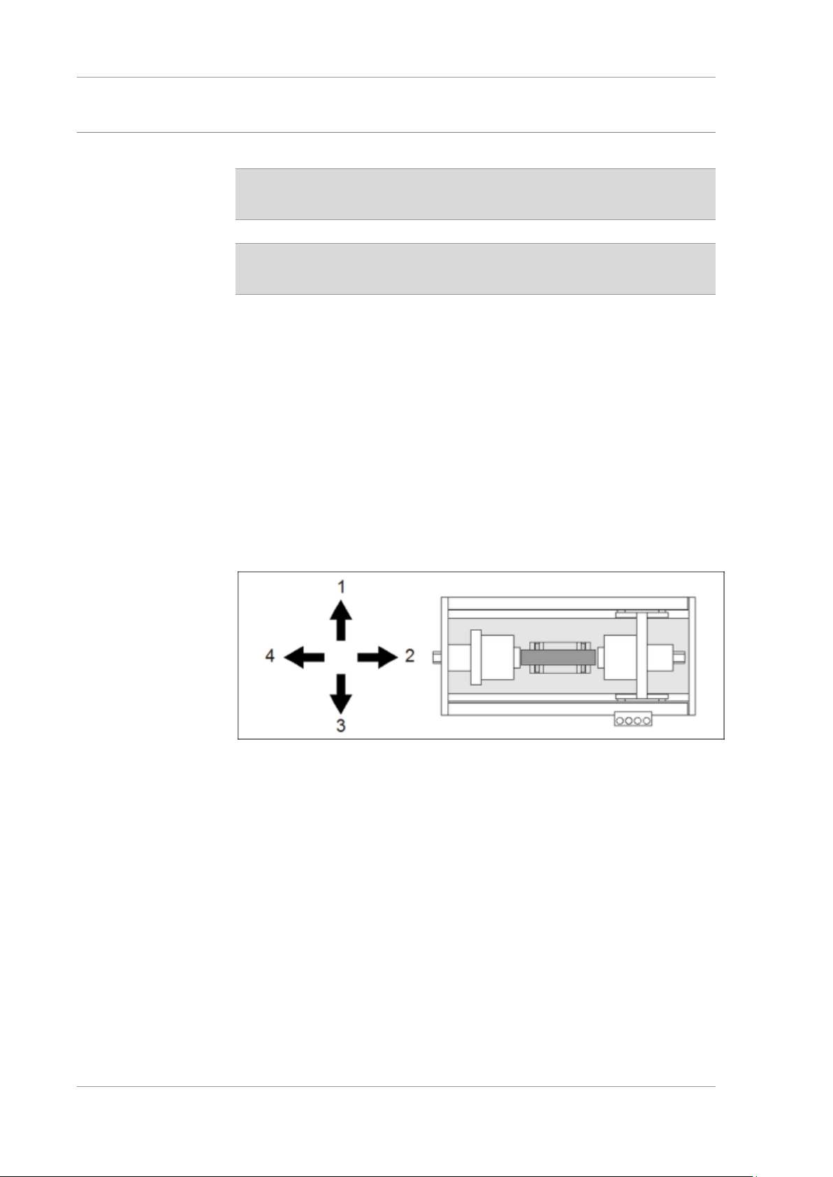
All directional and location references given in this manual refer to the main
workstation at the front of the machine.
Location references in the operating manual
[1]
rear
[2]
right
[3]
front
[4]
left
Page 10
General safety instructions UNIVERSAL WE TOUCH TCODE
10 / 85 MX UWETOUCH_v.3
2019-05-03
Action instructions
All tasks of the operating personnel are presented in a numbered list. Follow
the prescribed sequence of actions!
1
Operating action step 1
2
Operating action step 2
→ System response to operating action 2
Safety instructions
Safety instructions
• warn of immediate or possible hazards;
• inform about hazard prevention measures;
• describe measures for minimising risk;
• offer important information for safety-conscious behaviour.
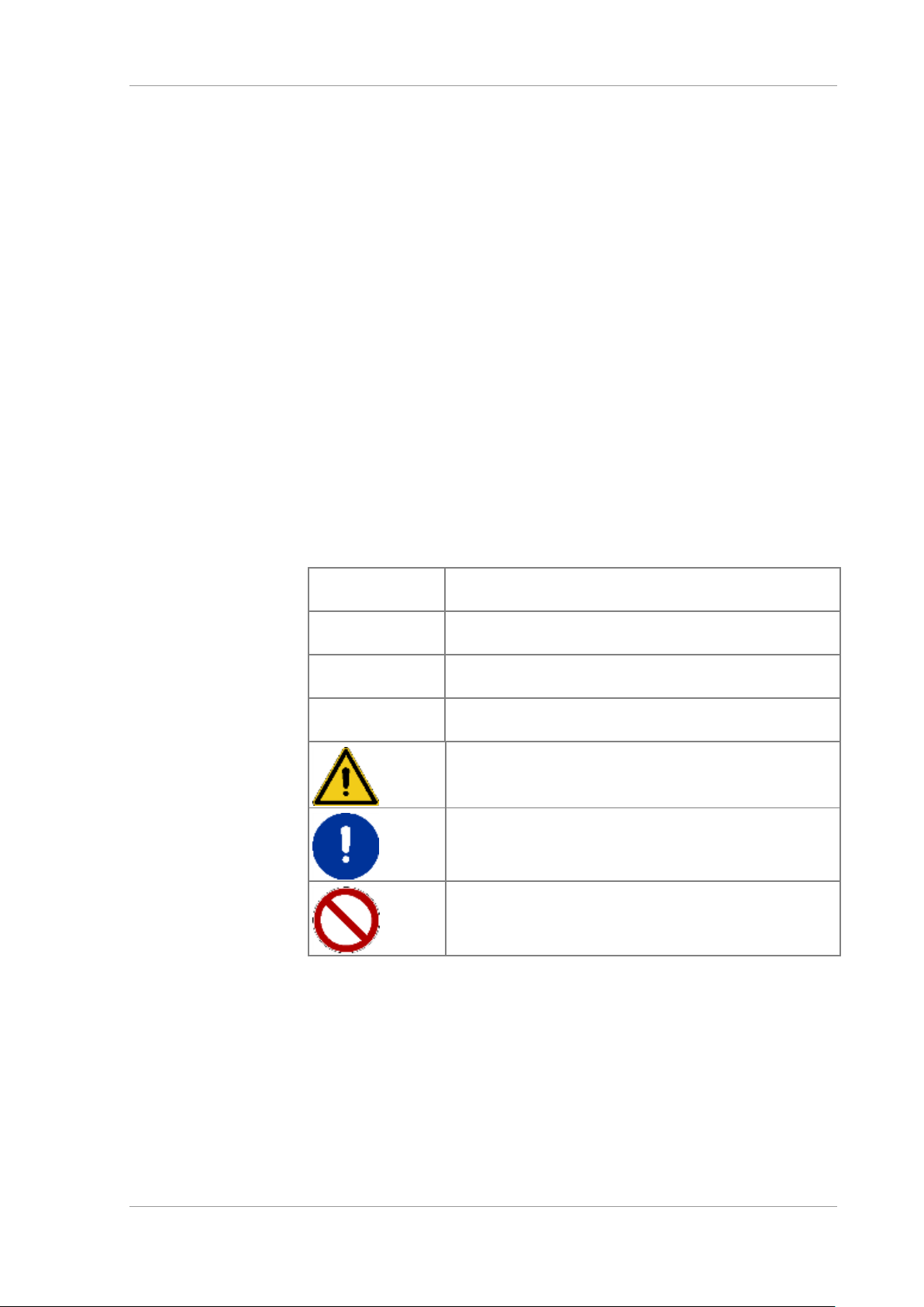
Safety instructions are denoted by a pictogram and a signal word.
• The pictogram describes the type of hazard.
• The signal word describes the severity of the hazard
Comply with safety instructions to avoid injury to yourself, to others, and
damage to material assets.
Signal words and symbols in safety instructions
DANGER
Immediate danger to life and health of personnel
(severe injury or death).
WARNING
Possible danger to life and health of personnel (severe
injury or death).
CAUTION
Possibly dangerous situation. Possible danger of injury
to personnel or material damage.
ATTENTION
Possibly dangerous situation. Possible danger of
material damage.
Warning of immediate or possible dangers.
Rule: Requirement for a specific behaviour or activity.
Measures to be absolutely observed!
Prohibition: Prohibits certain activities or conduct.
Page 11
UNIVERSAL WE TOUCH TCODE General safety instructions
MX UWETOUCH_v.3 11 / 85
2019-05-03
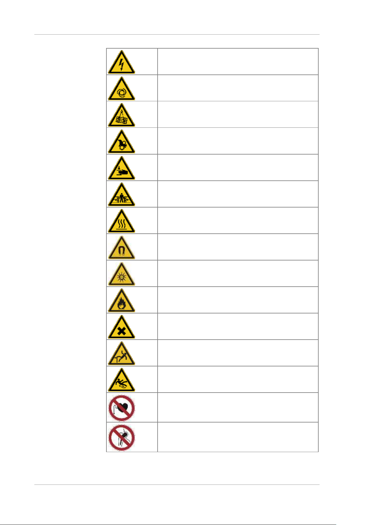
Hazard symbols in warning instructions
Danger due to high voltage. Possibility of electric shock
currents and burns. Comply with preventive measures
and safety rules.
Danger due to self-starting machines or components. Do
not remove or render inoperative any safety features.
Danger due to lifted loads. Danger of crushing when
loads are lowered. Danger from falling parts. Do not step
under raised loads.
Danger from powered components. Body parts and
clothing can be caught, pulled in and crushed. Do not
reach into powered components.
Danger of crushing for fingers and hands. Do not
remove any protective covers.
Danger of crushing to the body due to heavy workpieces
and/or powered machine components.
Danger due to hot surfaces. Burn hazard. Components
must only be touched after cool-down period has
elapsed or with hand protection.
Danger due to magnetic fields. Danger of interference
with medical implants. Access is prohibited for personnel
with medical implants.
Hazards due to UV radiation. Possible damage to skin or
eyes. Do not operate UV lamps without filter. Wear
personal protection equipment.
Fire hazard due to flammable substances. Avoid sparks
and naked flame. Keep fire extinguishers at hand.
Danger due to noxious substances. Avoid physical
contact. Read the safety data sheets of these
substances.
Danger of falling. Utilise safety equipment. Use suitable
climbing aids.
Danger of slipping on spilt products or auxiliary
substances. Cordon off area and clean the floor. Use
binding agents where necessary.
Danger due to magnetic fields. Access prohibited for
persons with pacemakers and other medical implants!
Danger due to magnetic fields. Access prohibited for
persons with metallic implants.
Page 12

General safety instructions UNIVERSAL WE TOUCH TCODE
12 / 85 MX UWETOUCH_v.3
2019-05-03
1.2 Hazards when handling the machine
Machine operation may pose hazards and adverse effects
• to the life and limb of operators or third parties,
• to the machine itself,
• and to other material assets.
Familiarity with the safety regulations and user instructions contained in this
manual forms the basis for safe handling and trouble-free operation of this
machine.
Severe injury to personnel and damage to material assets may be caused by
• improper installation and set-up,
• improper use,
• prohibited removal of safety covers or safety features.
Always comply with locally applicable safety regulations!
1.3 Emergency measures
In the event of an emergency, press the emergency stop button (where
available) or disconnect the machine from mains power immediately.
The main switch isolates the machine from mains power.
• The OFF position is marked “0”.
• The ON position is marked “1”.
The machine is isolated from mains power when the main switch is in the
OFF position.
The main switch can be locked in OFF position with a padlock.
Page 13
UNIVERSAL WE TOUCH TCODE General safety instructions
MX UWETOUCH_v.3 13 / 85
2019-05-03
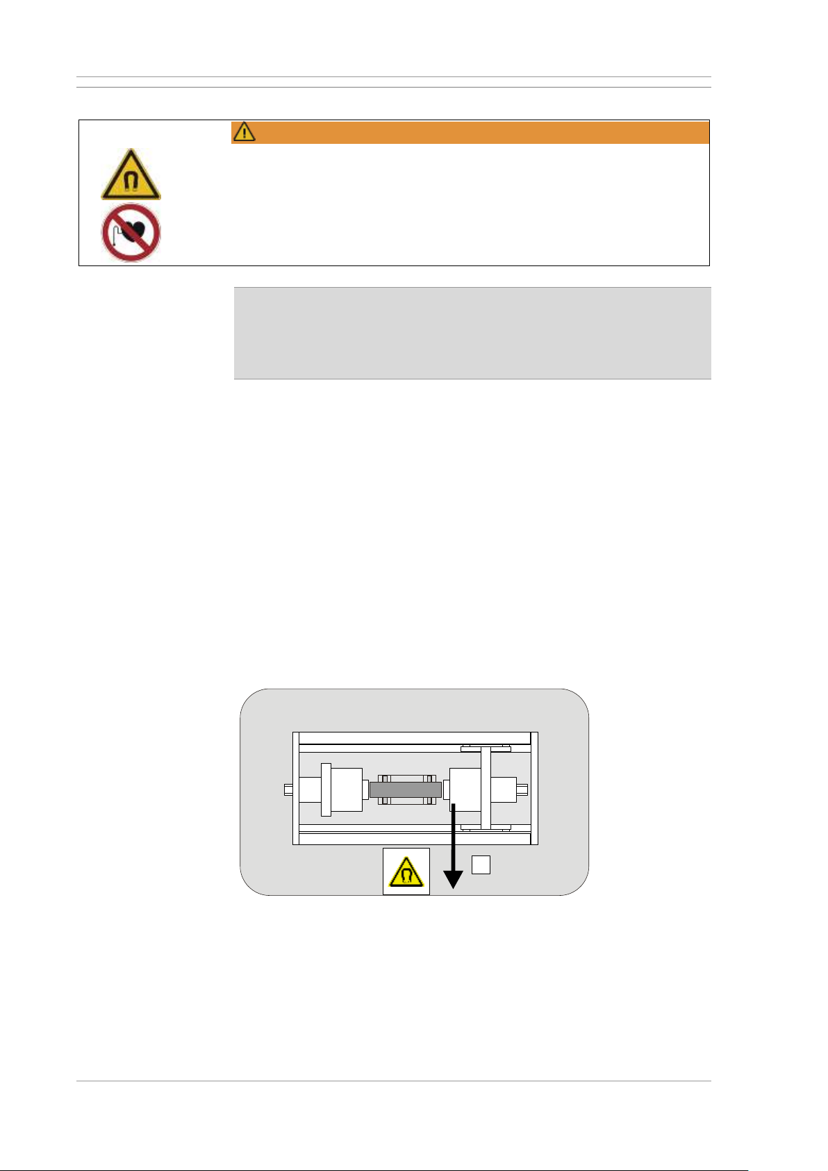
1.4 Magnetic loads at the workplace
WARNING
Magnetising may interfere with the proper function of pacemakers and other
medical implants, e.g. insulin pumps.
Lingering in the vicinity of the machine or within a perimeter of 5 m around
the magnetising station is prohibited for
• persons wearing medical aids and magnetisable implants
• pregnant women
• for persons under the age of 16
High magnetic field strengths during magnetising may cause damage
to health and have negative effects on medical implants.
• Comply with general and location-specific accident prevention
regulations.
• Maintain safety distance during magnetising.
The specified safety distance results from the limit values from
• the German accident prevention regulation DGUV V15 dated June 2001
• and the international guideline for the limitation of exposure to electrical,
magnetic and electromagnetic fields (ICNIRP) dated 2010.
In accordance with the German Accident Prevention Regulation DGUV V15,
the machine for magnetic crack testing is associated with exposure range 1.
Exposure range 1 applies to areas with controlled access, e.g. production
facilities.
Safety distance
Maintain the following safety distance from the magnetising device during
operation (magnetising current active):
• Persons without pacemakers: s=500 mm (1.5’)
• Persons with pacemakers: s=5000 mm (16’)
Areas of elevated exposure
Increased exposure will occur inside the marked areas (safety distance).
tmp-a008-000-00-00-00177
s
Page 14

General safety instructions UNIVERSAL WE TOUCH TCODE
14 / 85 MX UWETOUCH_v.3
2019-05-03
The operating company is required to determine, document and mark areas
of increased exposure. It must be ensured that
• only authorised and trained personnel work in these areas and
• the permitted values for brief and partial bodily exposure are not
exceeded or
• personal protective equipment preventing unacceptable increased
exposure is used.
Important: Magnetic fields penetrate walls!
Recommendation!
Since areas of increased exposure correlate directly with local conditions, we
recommend generally prohibiting access to areas with strong magnetic fields
for
• persons using medical implants, e.g. pacemakers,
• pregnant women,
• persons under the age of 16.
1.5 Mechanical hazards caused by driven machine parts
Electromotive and pneumatically driven machine parts can pull in or
crush fingers and hands.
• The machine is not operated with the protective covers removed.
• Do not reach into the running machine.
• Switch off the main switch before carrying out any maintenance
work in the working area of the machine.
1.6 Risk of crushing due to heavy workpieces
Heavy workpieces can crush hands.
• Do not reach between workpieces and machine components during
loading and unloading.
• Use hand protection.
1.7 Skin irritation caused by test substances
Ingredients of the test substance may cause skin irritation or other
health issues.
• Always comply with the instructions provided in the manufacturer's
safety data sheet when handling test substances.
Page 15
UNIVERSAL WE TOUCH TCODE General safety instructions
MX UWETOUCH_v.3 15 / 85
2019-05-03
1.8 High fire risk due to oily test liquids
Test oils are highly flammable! Fire hazard!
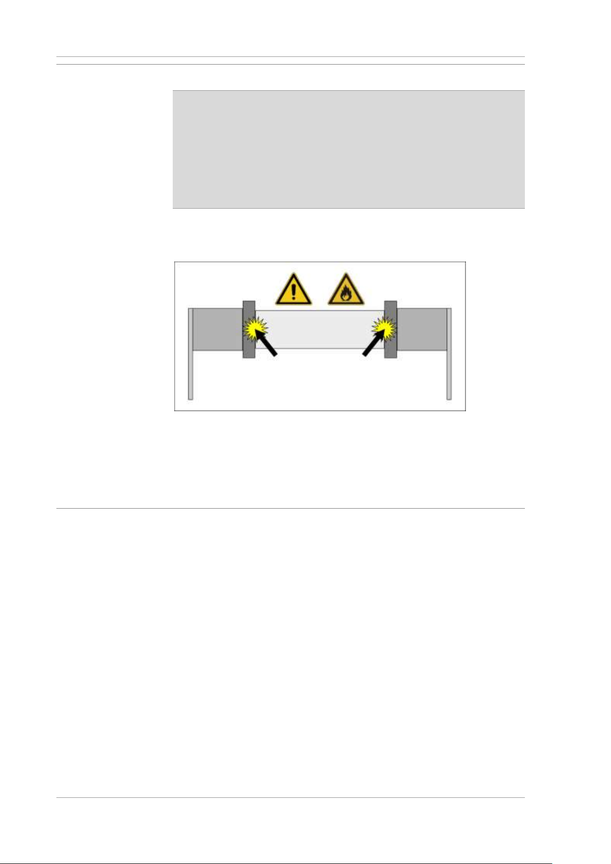
• Only use flame-retardant test oils with a flash point > 100°C.
(>212°F)
When using oily test liquids
• Have suitable fire extinguishers ready;
• always keep magnetising contacts clean;
• ensure compliance with instructions provided by the test liquid
manufacturer!
Dirty or corroded magnetising contacts, e.g. the folding coil, will lead to
excessive transition resistances at the contact points.
Contact points on the workpiece
The magnetising contacts must therefore be cleaned regularly. Maintenance
cycles are strongly dependent on use. Adjust maintenance intervals
according to your own experience.
1.9 Obligations of the operating company
The operating company undertakes to ensure that the machine is only
operated by persons, who
• are familiar with basic requirements regarding work safety and accident
prevention;
• have been trained in the operation of the machine;
• have read and understood this manual.
Contact the manufacturer with any remaining questions you may have.
Personnel training
The machine must only be operated by trained personnel. Personnel in
training must be supervised at all times when working on the machine.
Transport and set-up, supply line connections, commissioning, and
maintenance and repair work must only be performed by qualified personnel
with machine-specific training.
Page 16

General safety instructions UNIVERSAL WE TOUCH TCODE
16 / 85 MX UWETOUCH_v.3
2019-05-03
Personal protection equipment (PPE)
The following PPE is required when operating the machine.
• Safety gloves
• Safety boots
• Skin protecting agents
The operating company is required to make available all necessary PPE.
1.10 Defective protective and safety features
Faulty or dismantled safety features may result in hazardous situations.
Therefore:
1
Switch off machine immediately.
2
Secure against reactivation.
3
If necessary, disconnect from mains power.
1.11 Alterations or modifications
Additions or modifications to the machine without prior written approval of
the manufacturer are not permitted. Please contact the manufacturer if you
are planning any conversions.
1.12 Spare/ wear parts and consumables
The use of spare/ wear parts supplied by third party manufacturers may be
hazardous. Only use OEM parts or parts approved by the manufacturer.
The manufacturer shall not accept any liability for damage caused by nonapproved spare parts, wear parts or consumables.
Page 17

UNIVERSAL WE TOUCH TCODE Machine description
MX UWETOUCH_v.3 17 / 85
2019-05-03
2 Machine description
2.1 Intended use
Operational safety of this machine/system can only be guaranteed for the
intended use. The machine/installation is intended solely for materials testing
• of specified workpieces;
• using the magnetic powder process according to
– DIN EN ISO 9934-1:2002-03;
– DIN EN ISO 9934-2:2003-03;
– DIN EN ISO 9934-3:2002-10;
– ASTM E1444, E709, & E3024
• when stationary;
• within the limits specified below.
If there are any questions regarding optimised utilisation of the machine,
please contact the manufacturer.
Feeding the workpieces
The operating company must ensure that workpieces are checked and
fed into the magnetising station properly. The operating company must
supply all required equipment and ensure appropriate measures to
eliminate hazards due to moving or hoisted workpieces.
Use contrary to intended use
Use contrary to intended use can lead to injury or damage. The system must
not be operated
• in potentially explosive environments
• for mechanical or thermal processing of workpieces.
These types of use constitute a misuse of the system.
The operating company is solely responsible for any consequences
• from use other than intended use
• from actions not described in the operating manual.
The manufacturer accepts no liability for consequential damage. If used for
any other than the intended use, all warranty claims against the
manufacturer become null and void.
Work location
The system meets the requirements of the following standards with regards
to electromagnetic compatibility
• DIN EN 61000-6-4 VDE 0839-6-4:2011-09
Interference emission standard for industrial environments
• DIN EN 61000-6-2 VDE 0839-6-2:2006-03
Emission resistance standard for industrial environments
With regards to interference emission, the system is not suitable for use in
residential and small trade environments.
Page 18
Machine description UNIVERSAL WE TOUCH TCODE
18 / 85 MX UWETOUCH_v.3
2019-05-03
2.1.1 Specification of the workpieces
Only workpieces complying with the following specification may be tested
with the machine using the magnetic particle inspection method:
Workpieces
Workpieces made of ferromagnetic materials with
a magnetic conductivity of µ>100.
Clamping
length
600/900 mm (23”/35”)
Diameter
max. 300 mm (11.8”) (11.8”)
Weight
max. 100 kg (220 lbs) (220 lbs)
Flammability
Not self-igniting under pressure, friction and heat
Explosiveness
Not self-exploding under pressure, friction and heat
Please contact the customer service department of the manufacturer with
any questions regarding the products to be tested.
2.1.2 Limits of the machine
Field strength in the
workpiece
> 32 A/cm
Magnetising circuit 1
Variably adjustable up to max. 3000 A AC
(effective value) as option
Magnetising circuit 2
max. 15.000 AW (amp-turns) AC (effective value)
Activation cycle
Relative ED 60%, absolute ED max.30 s ON/ 20
s OFF at 50% of nominal power
Throughput/h
Depending on loading/ unloading times,
magnetising times, and assessment times
Permissible
temperature range
for operation
min. 10 °C (50°F), max. 35 °C (95°F)
Service life
A comprehensive safety inspection by the
manufacturer is required after 10 years of
operation. Please contact the manufacturer's
customer service department in good time.
Testing area
Crack indication is restricted or even impossible
• in the case of workpieces that deviate substantially from the specification,
• in the area of the bearing and contact regions of the workpiece,
• if an unsuitable test liquid is used,
• in severely contaminated workpieces.
Page 19
UNIVERSAL WE TOUCH TCODE Machine description
MX UWETOUCH_v.3 19 / 85
2019-05-03
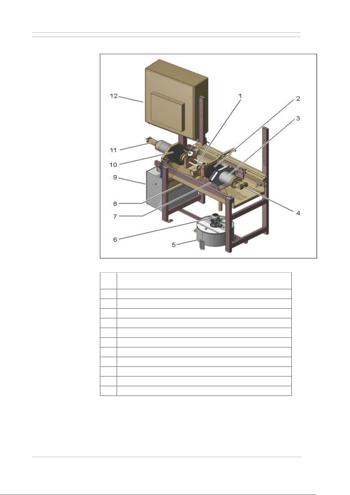
2.2 Structure of the machine
Machine components (standard version)
[1]
Magnetising mandrels(central conductor), installed in the left
sleeve
[2]
Coil of the magnetisation yoke in the right sleeve
[3]
Magnetisation yoke right sleeve
[4]
Clamping cylinder right sleeve (If installed)
[5]
Test liquid tank
[6]
Test liquid pump
[7]
Right tailstock
[8]
Pneumatic maintenance unit with pneumatic connection
[9]
Transformer cabinet
[10]
Coil of the magnetisation yoke in the left sleeve
[11]
Clamping cylinder left sleeve
[12]
Control cabinet with operating elements (main control console)
Page 20

Machine description UNIVERSAL WE TOUCH TCODE
20 / 85 MX UWETOUCH_v.3
2019-05-03
Magnetising station
Magnetising station
[1]
Clamping cylinder left sleeve
[2]
Coil of the magnetisation yoke in the left sleeve
[3]
Magnetising mandrels magnetising circuits 1 and 2
[4]
Workpiece supports
[5]
Mating contacts for magnetising mandrels
[6]
Coil of the magnetisation yoke in the right sleeve
[7]
Clamping cylinder right sleeve 1
[8]
Clamping cylinder right sleeve 2
[10]
Shower heads for test agent
[11]
Workpiece to be inspected
2.3 Safety equipment
WARNING
Only operate the equipment with all protection and safety features in place
and fully functional.
Check safety and protection features periodically.
The machine is equipped with the following safety and protection features:
• Main switch (mains isolation) on the control cabinet
• Two-hand control for activation of the pneumatic or electro-motor drives
Page 21
UNIVERSAL WE TOUCH TCODE Machine description
MX UWETOUCH_v.3 21 / 85
2019-05-03
2.4 Technical data
2.4.1 Dimensions and weights
For the type and equipment on your individual machines, refer to Page 5.
Magnetising station, depending on the type of machine
Width
approx. 2075 mm (81.5”)
Depth
approx. 950 mm (37.4”)
Height
approx. 2190 mm (without darkening cabin)
(86.2”)
Weight
approx. 600 kg (1322 lbs)
Weight of test liquid
tank
approx. 20 kg (44 lbs)
Overall space
requirement
about 2500 x 3000 mm (98” x 118”)
Space around the machine necessary for
operation, cleaning and maintenance work.
Refer to the assembly plan for mandatory specifications.
Optional darkening cabin
Width
approx. 2600 mm (102”)
Depth
approx. 2000 mm (78”)
Height
approx. 22440 mm (external height) (88”)
Weight
approx. 200-600 kg (440 – 1322 lbs) depending
on design
2.4.2 Electrical data
Supply voltage
AC 3x400 V / 50 Hz
Network system: TN-C-S
Power input
approx. 59/69 kVA
Control voltage
230 VAC
24 VDC
Construction-side
fuse protection
80/100 A inert (time delay)
Activation time
Relative ED 60%, absolute ED max.30 s ON/ 20
s OFF at 50% of nominal power
Page 22
Machine description UNIVERSAL WE TOUCH TCODE
22 / 85 MX UWETOUCH_v.3
2019-05-03
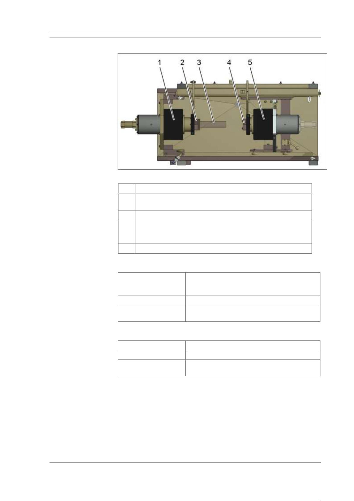
2.4.3 Magnetising circuits
Magnetising equipment
[1]
Coil of the magnetisation yoke in the left sleeve
[2]
Contact plate for axial (contact) current flow at the left spindle
sleeve. Optional holder for magnetising mandrel.
[3]
Optional attachable magnetising mandrel (central conductor)
[4]
Contact plate for axial (contact) current flow at the right spindle
sleeve, alternatively counter contact for operation with
magnetising mandrel
[5]
Coil of the magnetisation yoke in the right sleeve
Magnetising circuit 1: Circumferential magnetising
Magnetising
Axial (Contact) current flow or field flow with
inserted or attached conductor (circumferential
magnetising)
Current type
Alternating current (AC)
Magnetising current
Variably adjustable up to max. 3000 A AC
(effective value) as option
Magnetising circuit 2: Longitudinal magnetising, yoke (coil) magnetising
Magnetising
Yoke (Coil) magnetising
Current type
Alternating current (AC)
Flow
Variably adjustable up to max. 15.000 AW (ampturns) AC (effective value)
Page 23
UNIVERSAL WE TOUCH TCODE Machine description
MX UWETOUCH_v.3 23 / 85
2019-05-03
2.4.4 Clamping devices for the workpiece
Standard version with safety short stroke
Left sleeve
Pneumatically driven
Clamping distance
7 mm (.275”)
Clamping force
1680 N
Right tailstock
Manually adjustable, fixed in operation
Option: Clamping device on the right sleeve
Right sleeve
Manually adjustable, fixed in operation
Clamping distance
25 mm (.984”)
Clamping force
1 060 N
2.4.5 Workpiece holders
Model
Prism-shaped supports made of nonmagnetisable material
Workpiece holders for different workpieces are available. As required, please
contact the MAGNAFLUX GmbH sales department for more information.
2.4.6 Pneumatics
Air pressure
6 bar (90 psi)
Air quality
dry, oil-free, filtered
Compressed air
connection
Hose coupling, NW 7.2 mm
Oil capacity of
dosing oiler
250 ml (8.5 oz)
Oil type for
dosing oiler
Hydraulic oil compliant with DIN 51524 Part 2,
viscosity 32 mm²/s at 40°C (HLP 32)
Recommended oil
types for dosing oiler
Festo specialist oil OFSW-32, ARAL Vitam GF
32, ESSO Nuto 32, MOBIL DTE 24, BP Energol
HLP–HM 32
2.4.7 Test liquid system
Test liquid tank
capacity
40 l (10 Gal)
Supply voltage test
liquid pump
AC 400 V / 50 Hz (connects to Control panel)
Power supply for test
liquid pump
Socket of the magnetising station on base frame;
1.5 m connection cable on the pump; CEE-form
plug, 16 A, 5-pin
Page 24
Machine description UNIVERSAL WE TOUCH TCODE
24 / 85 MX UWETOUCH_v.3
2019-05-03
2.4.8 UV-LED lamp (sample)
For this, refer to the separate documentation for the UV lamp! Technical data
at this point only for non-committal information!
Manufacturer and type
Magnaflux UV-LED PANEL RADIATOR TYPE
365/30
Supply voltage
85-265 V AC / 47-63 Hz
Power input
approx. 70 W
Wavelength
365 nm ± 5 nm
UV-A intensity
maximum 65 W/m² (6.500 µW/cm²) at a distance
of 400 mm (13.5”)
UV-B/C emission
none
White light portion
< 8 Lux (.7 FC)
Dimensions
640mm (25”) x 300mm (11.8”) x 215mm (8.5”)
(LxDxH)
Weight
11.5 kg (25 lbs)
2.4.9 Ambient conditions
Operating
temperature
5 … 45 °C (41 … 113°F)
Storage temperature
5 … 55 °C (41 … 131°F)
Humidity during
operation
max. 90% relative humidity (non-condensing)
Humidity during
storage
max. 90% relative humidity (non-condensing)
2.4.10 Emissions
EMC
Suitable for industrial applications in accordance
with the EMC Directive and current EMC
standards.
Noise
Workplace related emission value at normal
operation: 75 dB (A). Measured in accordance
with DIN EN ISO 3744:2011-02
Page 25
UNIVERSAL WE TOUCH TCODE Machine description
MX UWETOUCH_v.3 25 / 85
2019-05-03
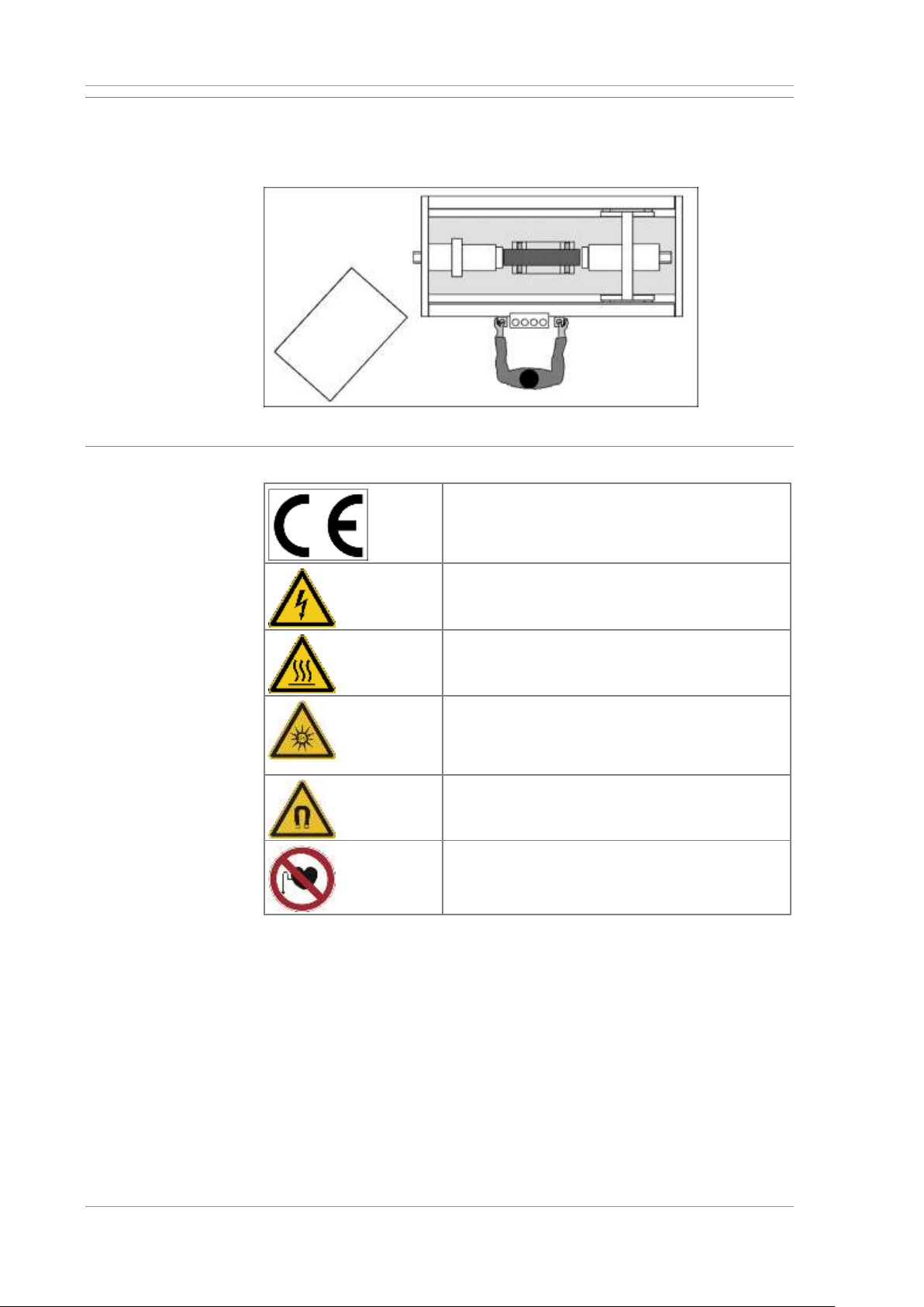
2.5 Operator work stations
The machine must only be operated by one person. The work station for
standard operation is at the front of the machine.
Work station at the machine
2.6 Markings and type plate on the machine
CE marking
Indicates conformity with applicable EU
regulations regarding the product, which require
a separate CE label.
Danger due to electric current. Work on the
electric system must only be carried out by
certified electricians.
Danger due to hot surfaces, e.g. on workpieces
or system components. Wear suitable protective
gloves.
Hazards due to UV radiation. Suitable PPE
(safety goggles and skin protection) is required,
and specific work instructions must be complied
with.
Danger due to magnetic fields. Access prohibited
for specific groups of people. See general safety
instructions.
Danger of interference with medical implants.
Access is prohibited for personnel with medical
implants.
Type plate
The type plate of the machine is mounted near the main switch on the
control cabinet.
It contains important information
• about the machine,
• about the power supply,
• about the manufacturer.
Page 26

Machine description UNIVERSAL WE TOUCH TCODE
26 / 85 MX UWETOUCH_v.3
2019-05-03
2.7 Testing liquid system and spraying of the workpiece
CAUTION
Test oils are highly flammable! Fire hazard!
• Only use flame-retardant test oils with a flash point > 100 °C (212 °F)
When using oily test liquids
• Have suitable fire extinguishers ready!
• ensure compliance with instructions provided by the test liquid
manufacturer!
Check test liquids regularly and replace as needed!
If the system is not used for more than one hour, but remains in
operation, it is necessary that the test liquid flows in the circuit.
Otherwise the test liquid heats up.
• The quality of the test liquid reduces!
• The test oils could become self-igniting at higher temperatures
Open the tap on the hose and place this in the test liquid collection
basin. Then switch on the constant spraying at the main control
console.
Test liquid
The correct concentration of test liquid is a decisive factor in the detection of
faulty workpieces. Please comply with mixing ratio instructions provided by
the manufacturer.
The test liquid for magnetic particle testing is a suspension containing
• a magnetising powder and
• a carrier medium, e.g. water or oil.
The test powder is frequently mixed with fluorescent dye. As a result, the
accumulation of test liquid in cracks becomes clearly visible under UV light.
Using the test liquid
A sufficient quantity of the test liquid must be evenly applied to the
workpiece. Therefore:
• ensure accurate mixing ratio of test powder and carrier medium,
• thoroughly mix the suspension before use,
• replace severely contaminated suspension.
Page 27
UNIVERSAL WE TOUCH TCODE Machine description
MX UWETOUCH_v.3 27 / 85
2019-05-03
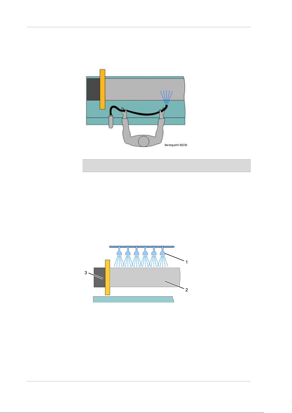
Spraying with hand-held shower or hose
You can spray the workpiece with test liquid manually, using the hand-held
hose or shower. The tap at the work station allows the machine operator to
shut off the test liquid line to the hand-held hose/ hand-held shower, and to
adjust the throughput volume individually.
Hand-held hose for spraying the workpiece
On machines with hand-held shower: Press the push-button in the
shower handle for spraying.
Tip: The hand-held hose/hand-held shower is also convenient for cleaning
the machine. Rinse the work area inside the test liquid collection basin
thoroughly before each test liquid change.
Spraying with large area shower (Option)
The machine can optionally be fitted with a large-area shower.
Thus, the workpiece [2] can be easily and uniformly sprayed with test liquid.
A tap is installed on each shower head [1] at which the flow rate can be
individually adjusted.
Optional large-area shower
[1]
Large-area shower
[2]
Workpiece
[3]
Magnetising equipment
Page 28
Machine description UNIVERSAL WE TOUCH TCODE
28 / 85 MX UWETOUCH_v.3
2019-05-03
Test liquid system
The test liquid unit consists of:
• the test liquid tank,
• the connecting lines,
• the hand-held hose or shower.
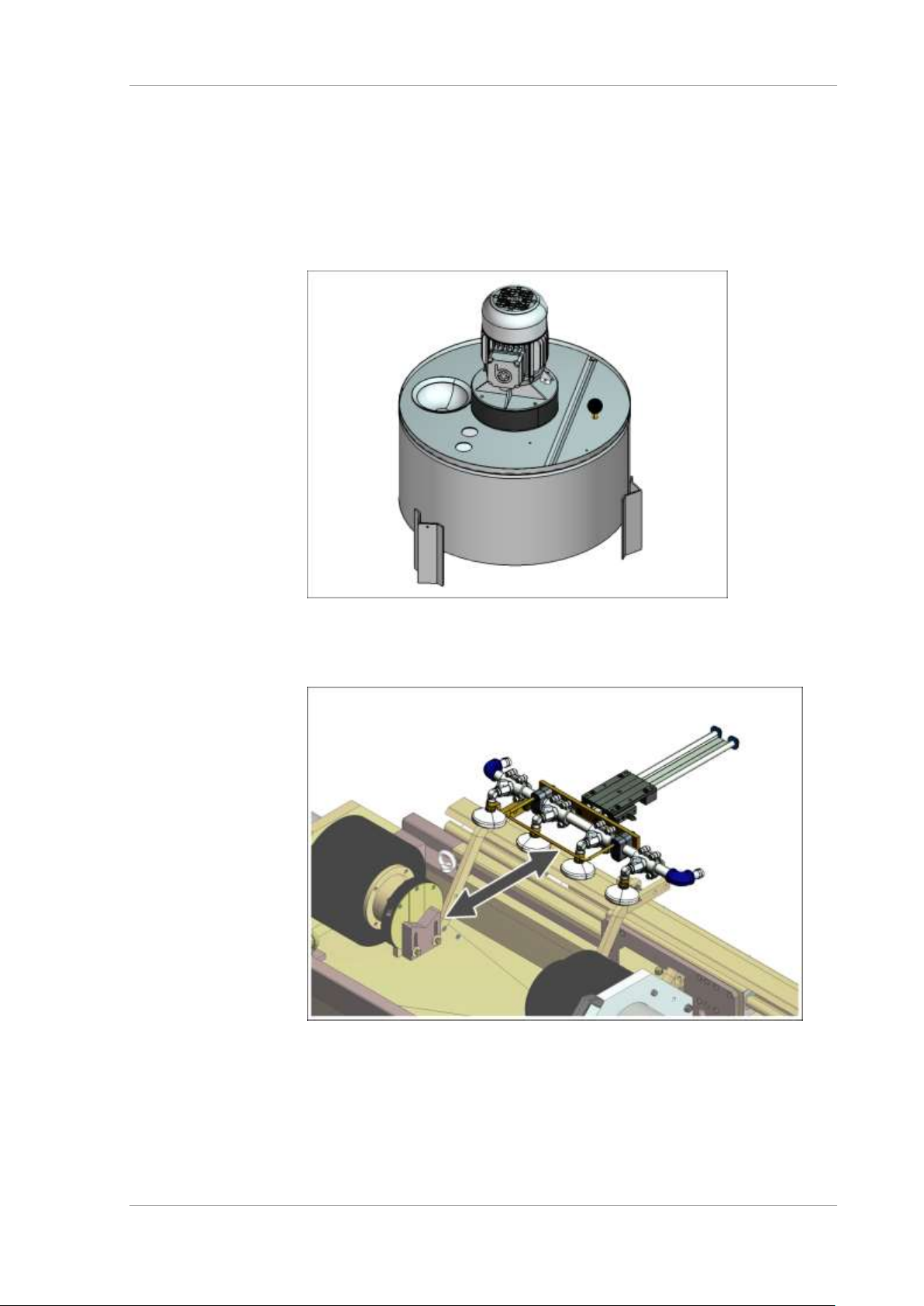
The test liquid flows in a closed circuit via the test liquid collection basin and
a dirt trap back to the test liquid tank.
Testing liquid tank with mounted testing liquid pump and dirt-trapping sieve in the
return flow
Adjustable shower heads
Horizontally adjustable shower heads
Note: Slide the shower heads over the workpiece at the handle to check the
workpiece.
Page 29
UNIVERSAL WE TOUCH TCODE Machine description
MX UWETOUCH_v.3 29 / 85
2019-05-03
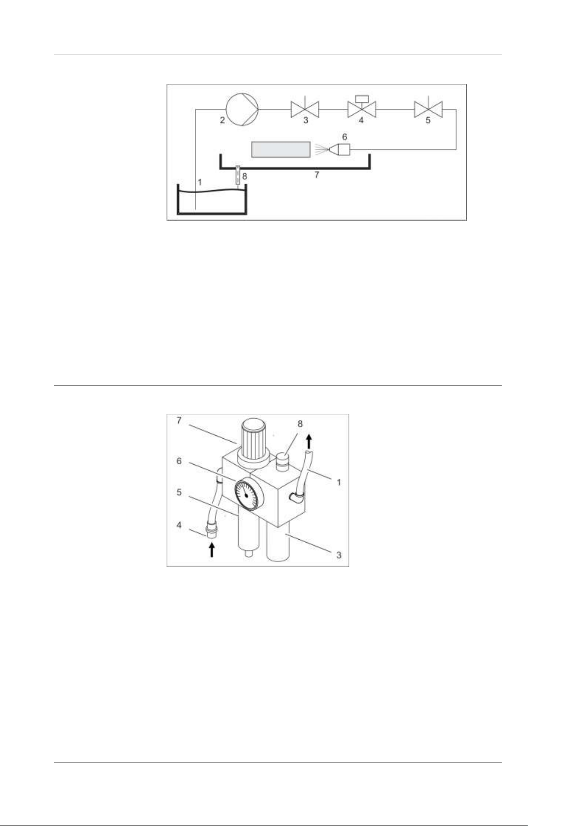
Test liquid circuit
Test liquid circuit
[1]
Test liquid tank
[2]
Pump
[3]
Stopcock, mounted on the test liquid tank (optional)
[4]
Solenoid valve
[5]
Stopcock at the workstation or the magnetising station (optional)
[6]
Test liquid nozzle
[7]
Test liquid collection basin
[8]
Return flow from the magnetising station with dirt trap
2.8 Pneumatic Maintenance Unit
Pneumatic Maintenance Unit
[1]
Compressed air output to the pneumatic system
[3]
Oil container (option)
[4]
Compressed air connection
[5]
Water separator with drain screw
[6]
Manometer
[7]
Pressure regulator
[8]
Setting screw and sight glass on dosing oiler
Page 30

Machine description UNIVERSAL WE TOUCH TCODE
30 / 85 MX UWETOUCH_v.3
2019-05-03
2.9 Individual test sequence
The machine can magnetise the workpiece with alternating current (AC).
In AC operation, the circuit magnetisation (e.g. axial (contact) current flow)
and the longitudinal magnetisation (yoke (coil) magnetisation) can be
operated separately or together. Thus, workpieces are checked for cracks in
the longitudinal direction, as well as for cracks around the circumference.
The machine operator manually feeds the workpiece, or via a transport
system from the customer (e.g. robot) into the workpiece mounts in the
machine.
The workpiece is clamped between two pneumatically operated
sleeves(refer to the overview of the machine equipment). The two contact
surfaces for axial (contact) current flow make contact with the workpiece.
The machine is ready to commence the magnetising process.
Alternatively for operation with magnetising mandrel:
A magnetising mandrel can be mounted on the left sleeve. This plunges into
ring-shaped or tubular workpieces during clamping and contacts at the
counter contact of the right spindle sleeve. During magnetisation, an annular
magnetic field forms around the magnetising mandrel and is transferred to
the workpiece.
In WE operation, the magnetisation takes place during the parametrised
shower time plus post-magnetisation time.
In manual mode, the magnetisation and showering is switched on with the
foot switch. The magnetising current remains on as long as the foot switch is
activated.
In automatic mode, magnetisation is started after the quills have been
tensioned.
• Spray time starts with the activation of the magnetising current and the
spray function.
• The spray function stops and remagnetising commences, once the spray
time has elapsed.
• The magnetising current is deactivated once the remagnetising time has
elapsed.
• The sleeves are released and the workpiece can be removed from the
machine by the loading and unloading system.
2.10 Home position of the machine
• Sleeves released.
• Magnetising current and spray function switched off.
• Where available: Workpiece rotary drive switched off.
• No active fault.
Page 31

UNIVERSAL WE TOUCH TCODE Machine description
MX UWETOUCH_v.3 31 / 85
2019-05-03
2.11 Magnetising the workpiece
2.11.1 Constant current control
The strength of the actual magnetising current depends on the resistance in
the circuit. The magnetic field strength in the workpiece is a result of the
current output.
The constant current control regulates the voltage in the magnetising circuit
as a function of the actual current. The actual current value during the entire
magnetising cycle is maintained in accordance with the pre-selected nominal
value.
2.11.2 Current flow monitoring
During magnetising, the actual magnetising current value is
• continuously measured and
• compared to the pre-set nominal value.
A current flow fault is reported if current is absent or too low.
Current flow monitoring
• functions in manual and automatic operation
• does not function in an intensity range setting of 0-10%
The magnetising cycle is repeated in the event of a current flow fault. A fault
is reported and the machine is stopped if the nominal value is not reached.
Page 32

Machine description UNIVERSAL WE TOUCH TCODE
32 / 85 MX UWETOUCH_v.3
2019-05-03
2.11.3 Magnetising types in accordance with EN ISO 9934-1
The magnetising types available on the machine depend on the
machine model and accessories installed.
Contact the Magnaflux GmbH sales department for information
regarding required machine components.
DIN EN ISO 9934-1 deals with magnetic particle inspection in general, and
covers the magnetising types available for workpiece magnetising.
The most common magnetising types are described in the following brief
overview.
Axial current flow
Magnetising by axial current flow. Inherent current flow – workpiece is in
direct contact and behaves like an electrical conductor.
• Circular magnetic field around the workpiece.
• Displays longitudinal cracks in the workpiece
Induction flow
Magnetising by axial current flow. Circular workpiece forms the secondary
winding (1 winding in short circuit) of a transformer.
• Circular magnetic field around the workpiece cross-section.
• Displays longitudinal cracks in the workpiece
Yoke magnetising (stationary system)
Magnetising by way of field current flow. Workpiece in the magnetic field
between two yokes of an electromagnet
• Displays transverse cracks in the workpiece
Field current flow with inserted or attached conductor
Magnetising by current conductor (auxiliary flow). Magnetising mandrel in
tubular or circular workpieces, or in parallel contact with the workpiece.
• Circular magnetic field around the conductor and the workpiece.
• Displays longitudinal cracks in the workpiece
Field current flow via a fixed coil
Magnetising via a conducting coil (field current flow).
• Circular magnetic fields around the conductors accumulate inside the coil
to form a common longitudinal field.
• Displays transverse cracks in the workpiece
Page 33
UNIVERSAL WE TOUCH TCODE Machine description
MX UWETOUCH_v.3 33 / 85
2019-05-03
2.11.4 Demagnetising of workpieces
After surface crack testing using the magnetic particle inspection method,
a residual magnetic force will remain in the workpiece. Eliminating this
magnetic residue will help avoid negative effects during later processing or
when using the workpieces.
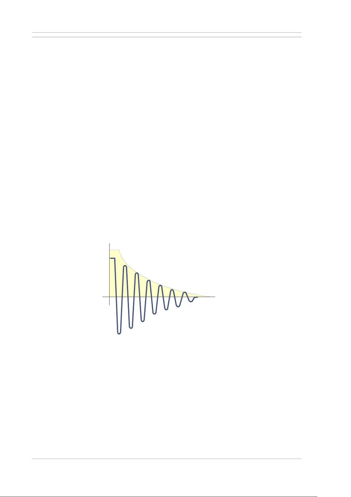
The field strength in the workpiece may by reduced by two methods:
• internally - he magnetising current is controlled towards zero along an
e-function. Demagnetising immediately follows magnetising in the crack
testing machine.
• externally - here the workpiece is demagnetised by an external coil
(see Magnaflux products, type ETT). The workpiece is continuously
moved out of the magnetic field.
Electronic demagnetising
A magnetising with alternating current must be followed by an AC
demagnetising. The electronic current control unit continually controls the
magnetising current along an e-function towards zero.
For demagnetising,
• a field with alternating polarity must be present, and
• field strength must continuously decrease towards zero.
Electronic demagnetising works according to the following principle:
• The workpiece is magnetised in a regular magnetising cycle with a
pre-set magnetising current.
• After spraying and at the end of the remagnetising time, the magnetising
current is gradually controlled towards zero along an e-function.
Course of magnetising current during demagnetising
Where magnetising uses direct current, demagnetising uses low frequency,
pulsed direct current of alternating polarity.
H
t
tmp-0000-ma1-00-00-00011
e
Page 34
Machine description UNIVERSAL WE TOUCH TCODE
34 / 85 MX UWETOUCH_v.3
2019-05-03
2.12 Lighting on the workstation
The lighting at the assessment workstation depends on a number of
parameters:
• Type of workpiece and workpiece surface
• Test liquid
• Lighting conditions at the workplace
Avoid glare from reflective surfaces on the workpiece and unfavourably
positioned light sources.
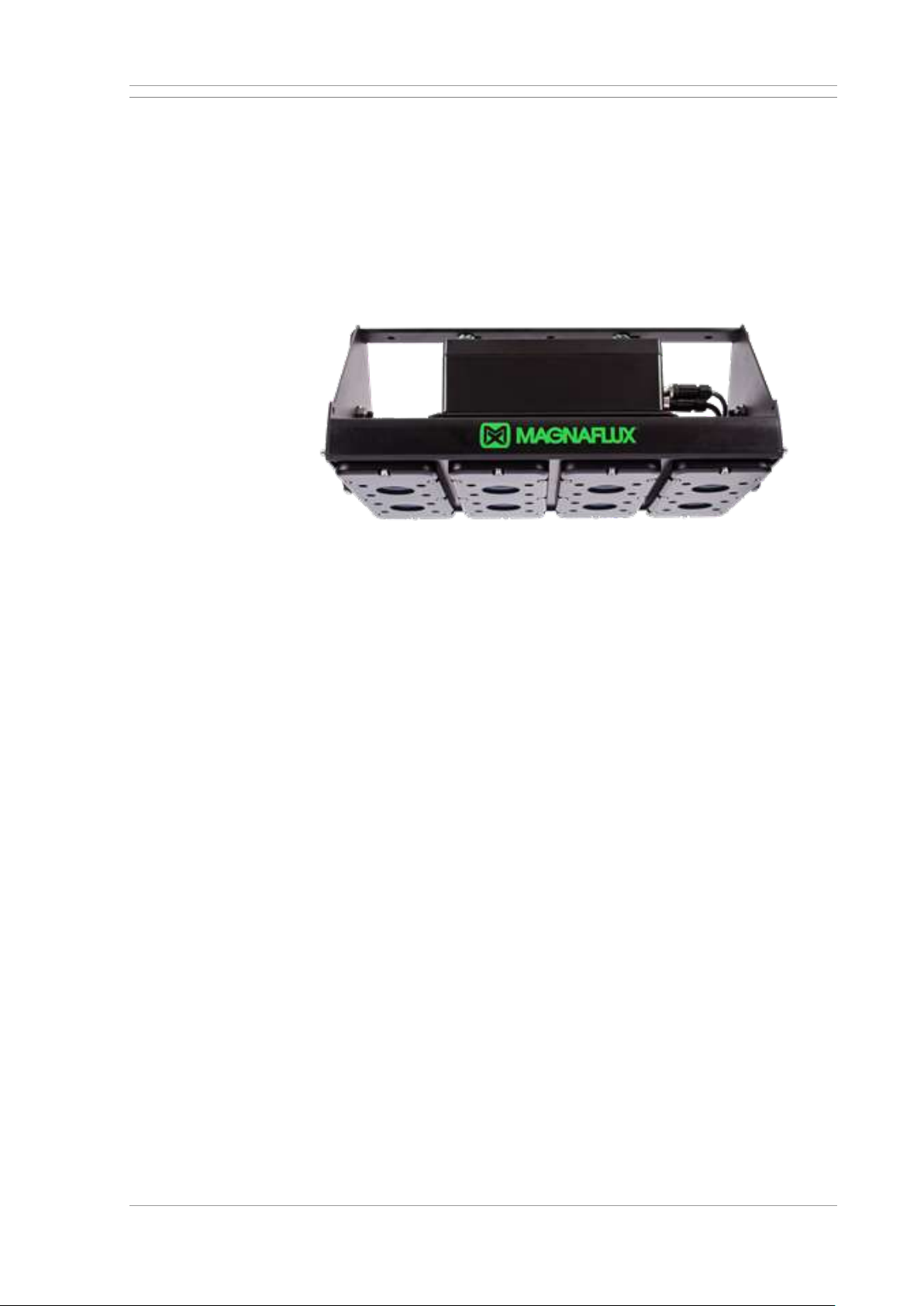
Magnaflux UV-LED panel lamp ST700
If you are using test liquids without fluorescent dyes, an illumination intensity
of at least 500 lux on the workpiece is recommended.
If you are using fluorescent test liquids, then
• workpieces should only be inspected under UV light,
• and the UV light intensity should not be less than 1000 μW/cm²,
• regularly inspect the UV lamps.
Page 35
UNIVERSAL WE TOUCH TCODE Machine description
MX UWETOUCH_v.3 35 / 85
2019-05-03
2.13 Visual inspection
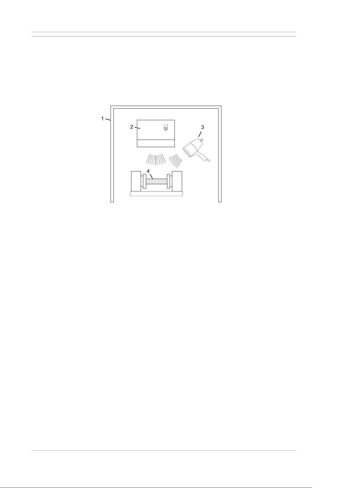
Visual inspection is frequently used as the method of inspection for the
workpieces.
As a rule, the machine operator inspects the workpieces visually directly in
the machine or at a special assessment station.
The accumulations of test liquid typical for cracks in the workpiece are
clearly visible as a result of the fluorescent test liquid and the UV lighting. It
is best if external light is shielded by a dark booth.
Visual inspection of the workpieces in the machine
[1]
Dark booth (optional)
[2]
UV lamp
[3]
UV hand-held lamp (optional)
[4]
Workpiece
UV!
UV!
tmp-0000-be1-00-00-00195
Page 36
Basis of operation UNIVERSAL WE TOUCH TCODE
36 / 85 MX UWETOUCH_v.3
2019-05-03
3 Basis of operation
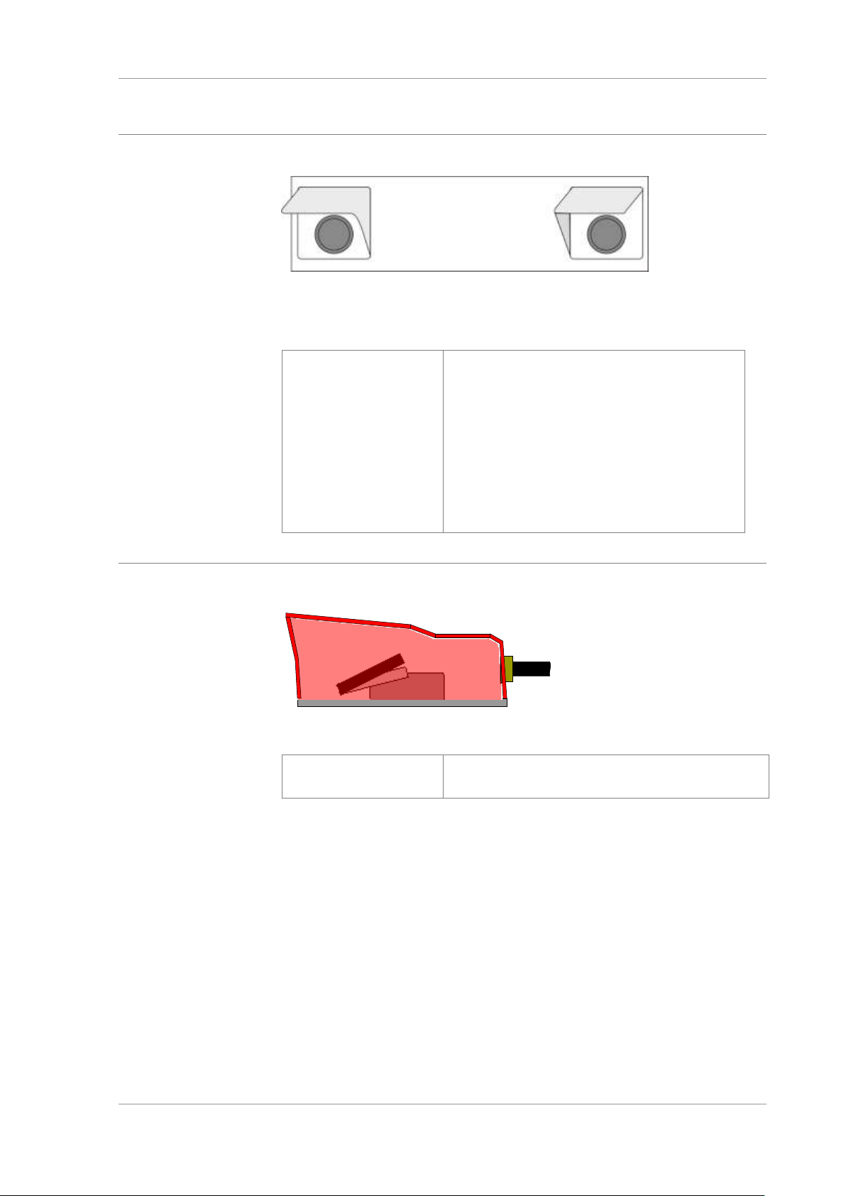
3.1 Option: Two-handed operation
Two-had operation on the workstation
Where any power-driven components might pose a hazard to operating
personnel, their operation is triggered by the two-handed control.
Function
To clamp the sleeves.
Carry out the function: Simultaneously press
and hold the two push-buttons until the function
ends, e.g. the end position has been reached
In case of imminent danger, simply release
one of the two buttons. The drive stops
immediately.
Important! Keep both buttons pressed until the
status display clamped is displayed on the
control panel.
3.2 Pedal switch
Pedal switch
Function
Switching on magnetisation in manual operation.
Prerequisite: Sleeves tensioned.
Page 37
UNIVERSAL WE TOUCH TCODE Basis of operation
MX UWETOUCH_v.3 37 / 85
2019-05-03
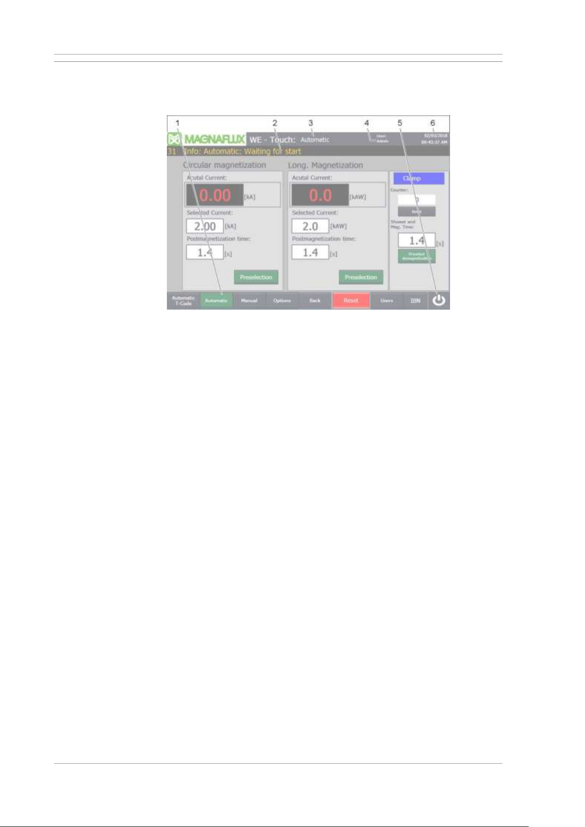
3.3 Touch control panel on the main control panel
3.3.1 Screen layout
The most important buttons and displays
[1]
Control buttons: Selection of the operating mode and screens
[2]
Display: Event and alarm messages
[3]
Display: Current operating mode or name of current screen
[4]
Currently logged in user
Note: No user login is required for test operation. To set up the machine
(e.g. change T-code data records), a user login is mandatory.
[5]
Button: End runtime program of the control panel!
Important: After termination, the machine can no longer be used for
test operation. A restart of the runtime from the Windows interface is
necessary.
Only touch the button for service purposes!
[6]
Display: Date and time.
Note: The current date and time can be set in the Options screen.
Page 38
Basis of operation UNIVERSAL WE TOUCH TCODE
38 / 85 MX UWETOUCH_v.3
2019-05-03
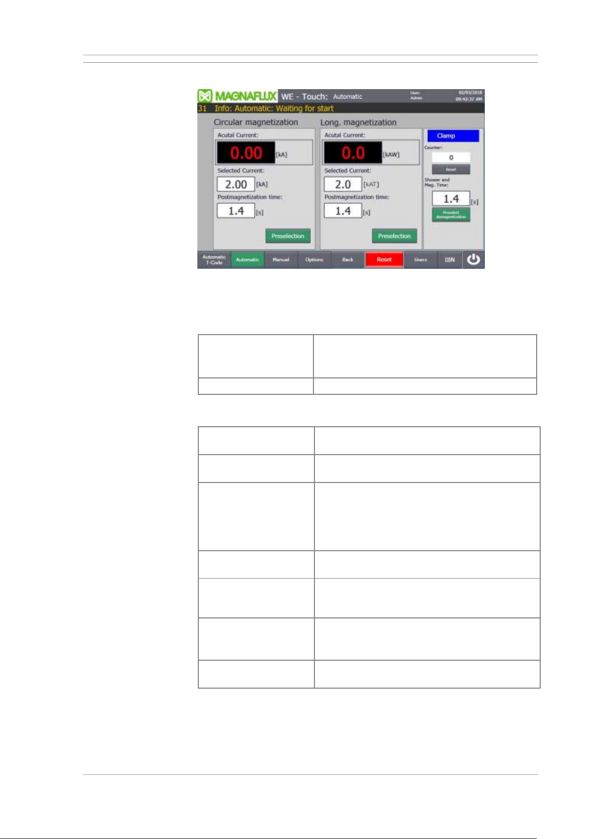
3.3.2 Automatic mode
Operation in AUTO mode
Display
The image is displayed automatically after the controller is switched on and
in automatic mode.
Automatic operation
Press the Automatic button at the bottom of the
screen.
→ Automatic mode is active.
Back
Close screen and display the last displayed image.
Preselections, setpoints and actual values for magnetisation
Preselection of current
flow
Switch the magnetisation circuit for axial (contact)
current flow or auxiliary flow on or off.
Preselection of yoke
magnetising
Switch the magnetising circuit for yoke (coil)
magnetising on or off.
Current set points
Setpoints of the magnetising currents
• for magnetising circuit 1 in kA
• for magnetising circuit 2 in kAW (amp-turns)
(current flow x number of turns)
Limit values: See Machine limits in chapter 2.
Setpoints for postmagnetisation times
Duration of magnetisation after showering.
Shower and
magnetisation time
set point
Duration of magnetisation with showering.
Preselection of
demagnetising
Switch automatic demagnetising on or off.
With demagnetising active, the workpiece is
subsequently demagnetised after magnetising.
Digital displays actual
values
Display of the current magnetising currents of the
preselected magnetising circuits.
Page 39
UNIVERSAL WE TOUCH TCODE Basis of operation
MX UWETOUCH_v.3 39 / 85
2019-05-03
Status display for clamping device
Clamp blue
Workpiece clamping devices (sleeves) are relaxed
and can be clamped.
Depending on the version, press the two-hand
control or foot switch until the status display
changes to green.
In automatic mode, the magnetisation cycle is
started after clamping.
Clamping green
Clamping devices are tensioned and can be
relaxed.
In automatic mode, the clamping devices are
automatically released after magnetisation.
Relax manually: Depending on the version, press
the two-hand control or foot switch until the status
display changes to green.
Workpiece counter
Display number of
pieces
Number of inspected workpieces since last reset.
Reset
Set the current count to zero.
Other functions
Demagnetising
Starting demagnetising.
Switch on the magnetising current as long as the
button is pressed. After release, the magnetising
current is regulated towards zero and the
workpiece is demagnetised.
Shower
Switching the test liquid pump on and off.
Reset
Button lights up bright red: Fault detected and
message not acknowledged.
Touch the button: Stop the active sequence, e.g.
acknowledge demagnetisation and/or fault
message when the cause has been eliminated.
Page 40
Basis of operation UNIVERSAL WE TOUCH TCODE
40 / 85 MX UWETOUCH_v.3
2019-05-03
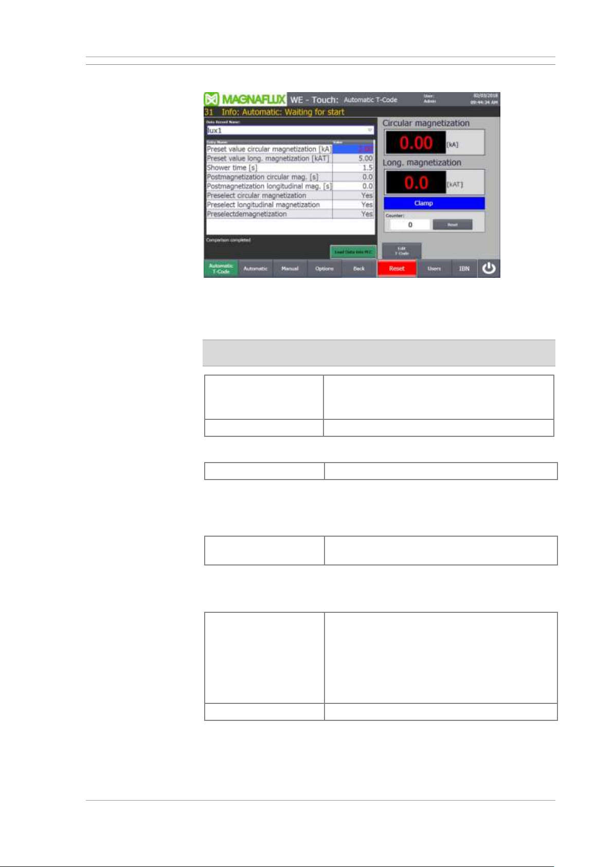
3.3.3 Automatic T-Code mode
Operation in AUTO mode
Display
The screen is shown in Automatic T-Code mode.
Prerequisite: The T-Code option is enabled on the machine. Please
contact the sales department if necessary.
Automatic T-Code
mode
Press the Automatic T-Code button at the
bottom of the screen.
→ Automatic T-Code mode is active.
Back
Close screen and display the last displayed image.
T-Code input and display fields
Dataset name
Name of the currently selected record.
The setpoints below are stored in the part-specific data records. When
loading a data set, these setpoints are transferred to the machine control.
For a description of the individual setpoints, see the instructions for setting
the magnetisation parameters in Chapter 4.
Entry name
Names and currently set values of the individual
magnetisation parameters.
Note: In this screen, only saved data sets can be selected, but no entries
can be edited. See also the “Edit T-Code” screen
Write data set to PLC
Transfer parameter values from the currently
selected dataset into the machine controller.
In automatic mode, these parameter values are
used for testing the workpieces.
If a new data set has been selected, this button
flashes and the transfer must be started by the
operator.
Edit T-Code
Display Edit T-Code screen.
Page 41
UNIVERSAL WE TOUCH TCODE Basis of operation
MX UWETOUCH_v.3 41 / 85
2019-05-03
Actual values for magnetisation
Digital displays actual
values
Display of the current magnetising currents of the
preselected magnetising circuits.
Status display for clamping device
Clamp blue
Workpiece clamping devices (sleeves) are relaxed
and can be clamped.
Depending on the version, press the two-hand
control or foot switch until the status display
changes to green.
In automatic mode, the magnetisation cycle is
started after clamping.
Clamping green
Clamping devices are tensioned and can be
relaxed.
In automatic mode, the clamping devices are
automatically released after magnetisation.
Relax manually: Depending on the version, press
the two-hand control or foot switch until the status
display changes to green.
Workpiece counter
Display number of
pieces
Number of inspected workpieces since last reset.
Reset
Set the current count to zero.
Other functions
Reset
Button lights up bright red: Fault detected and
message not acknowledged.
Touch the button: Stop the active sequence, e.g.
acknowledge demagnetisation and/or fault
message when the cause has been eliminated.
Page 42
Basis of operation UNIVERSAL WE TOUCH TCODE
42 / 85 MX UWETOUCH_v.3
2019-05-03
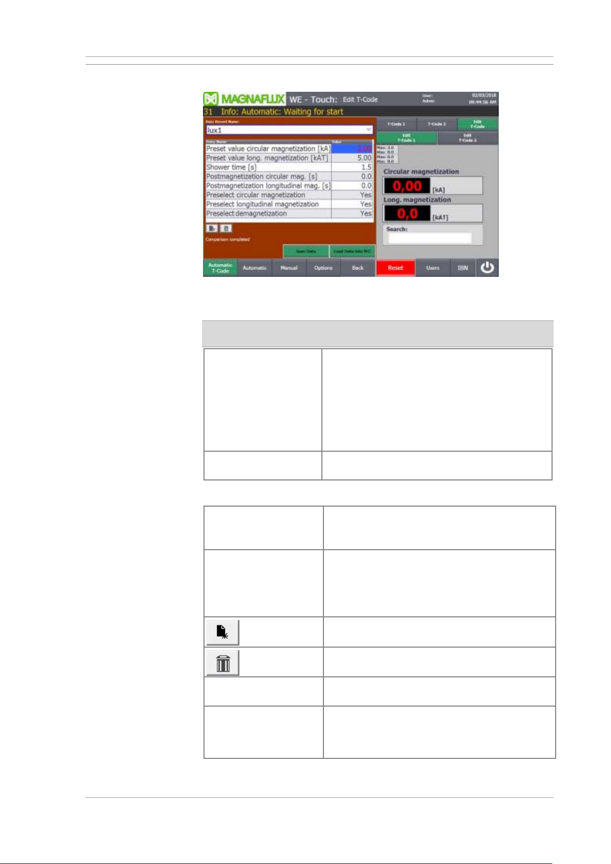
3.3.4 “Edit T-Code” screen
Edit T-Code data record
Open
Prerequisite: The T-Code option is enabled on the machine.
Please contact the sales department if necessary.
Edit T-Code
Prerequisite: Login as user (user or
administrator) required!
Press the Automatic T-Code button at the
bottom of the screen.
→ The Automatic T-Code screen appears.
Press the Edit T-Code button.
→ The Edit T-Code screen appears.
Back
Close screen and display the last displayed
image.
T-Code input and display fields
Dataset name
Name of the currently selected record.
Select a dataset: Open the list of already saved
data records and mark the desired data record.
Entry name
Names and currently set values of the individual
magnetisation parameters.
The values can be edited. Refer to the
instructions for setting up the magnetising
parameters in chapter 4.
Create new dataset.
Delete currently selected data set.
Save data record
Save the set parameter values in the currently
selected dataset.
Write data set to PLC
Transfer parameter values from the currently
selected dataset into the machine controller. In
automatic mode, these parameter values are
used for testing the workpieces.
Page 43
UNIVERSAL WE TOUCH TCODE Basis of operation
MX UWETOUCH_v.3 43 / 85
2019-05-03
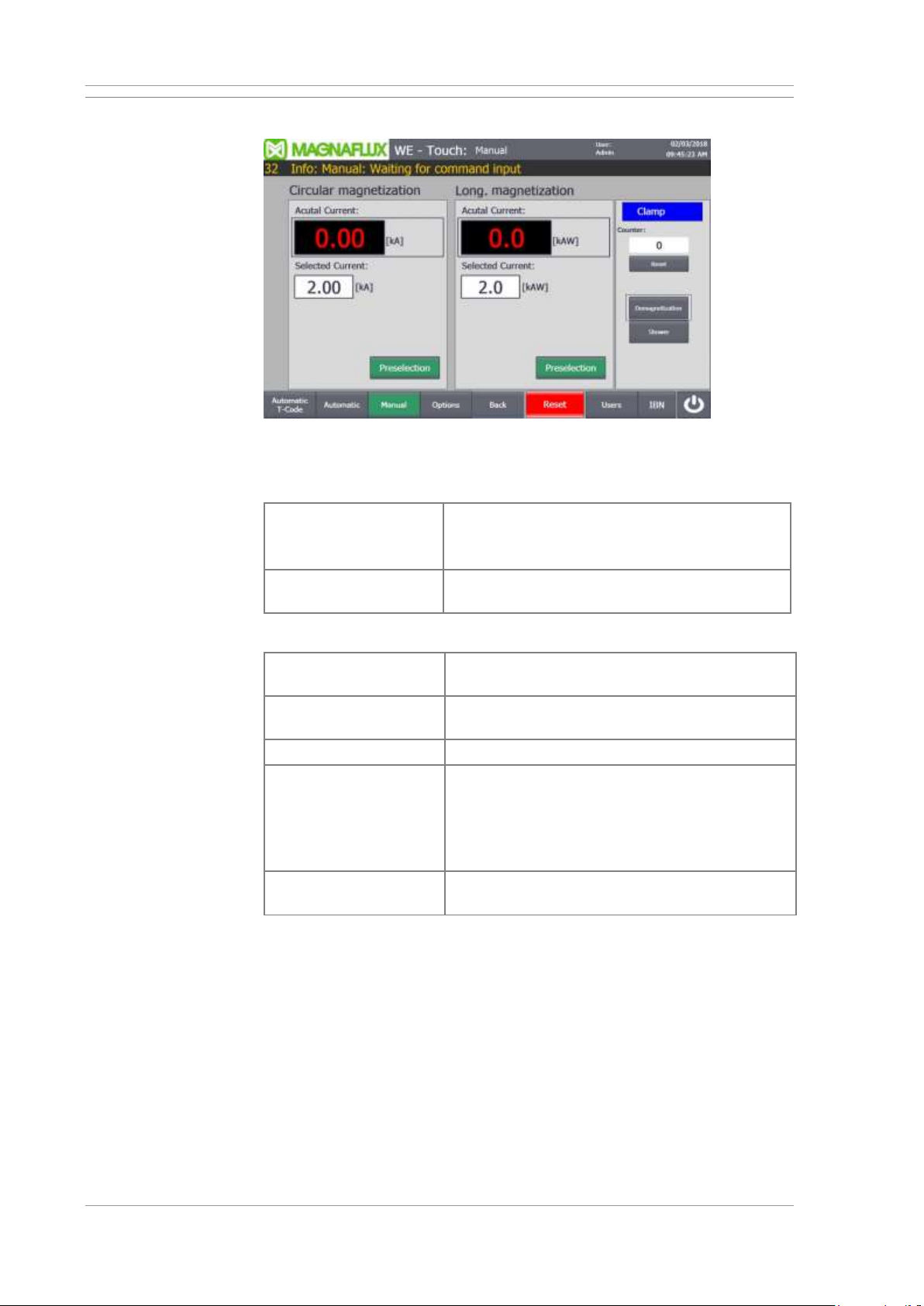
3.3.5 Manual operation mode
Operation in “Manual mode”
Display
The screen is shown in Manual mode.
Manual
Press the Manual button at the bottom of the
screen.
→ Manual mode is active.
Back
Close screen and display the last displayed
image.
Preselections, setpoints and actual values for magnetisation
Preselection of
current flow
Switch the magnetisation circuit for axial (contact)
current flow or auxiliary flow on or off.
Preselection of yoke
magnetising
Switch the magnetising circuit for yoke (coil)
magnetising on or off.
Selection
Selection of the respective magnetising circuits.
Current set points
Setpoints of the magnetising currents
• for magnetising circuit 1 and 2 in kA
• for magnetising circuit 3 in kAW (current flow x
number of turns (amp-turns))
Limit values: See Machine limits in chapter 2.
Digital displays
actual values
Display of the current magnetising currents of the
preselected magnetising circuits.
Page 44
Basis of operation UNIVERSAL WE TOUCH TCODE
44 / 85 MX UWETOUCH_v.3
2019-05-03
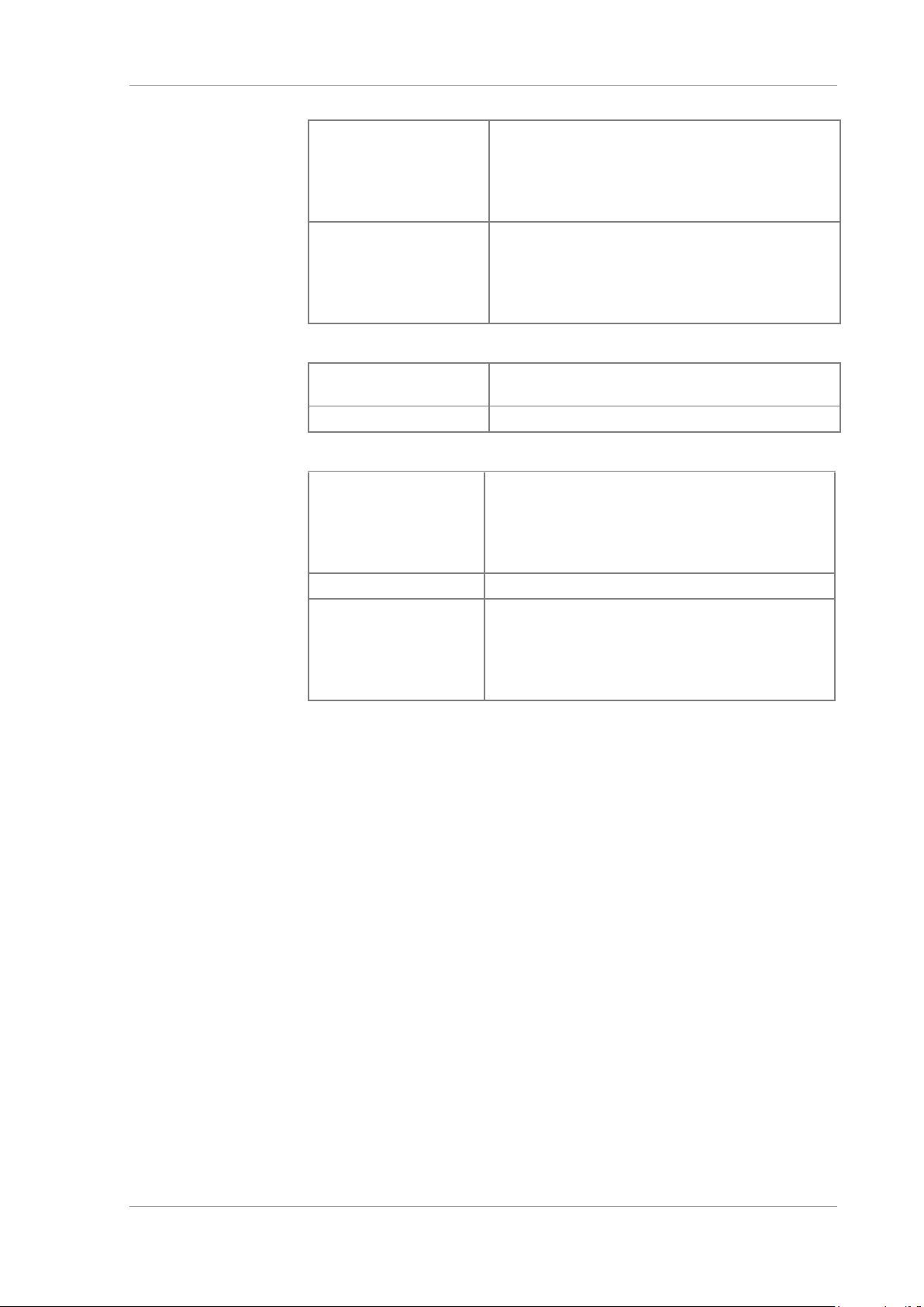
Status display for clamping device
Clamp blue
Workpiece clamping devices (sleeves) are
relaxed and can be clamped.
Depending on the version, press the two-hand
control or foot switch until the status display
changes to green.
Clamping green
Clamping devices are tensioned and can be
relaxed.
Depending on the version, press the two-hand
control or foot switch until the status display
changes to blue.
Workpiece counter
Display number of
pieces
Number of inspected workpieces since last reset.
Reset
Set the current count to zero.
Other functions
Demagnetising
Starting demagnetising.
Switch on the magnetising current as long as the
button is pressed. After release, the magnetising
current is regulated towards zero and the
workpiece is demagnetised.
Shower
Switching the test liquid pump on and off.
Reset
Button lights up bright red: Fault detected and
message not acknowledged.
Touch the button: Stop the active sequence, e.g.
acknowledge demagnetisation and/or fault
message when the cause has been eliminated.
Page 45
UNIVERSAL WE TOUCH TCODE Basis of operation
MX UWETOUCH_v.3 45 / 85
2019-05-03
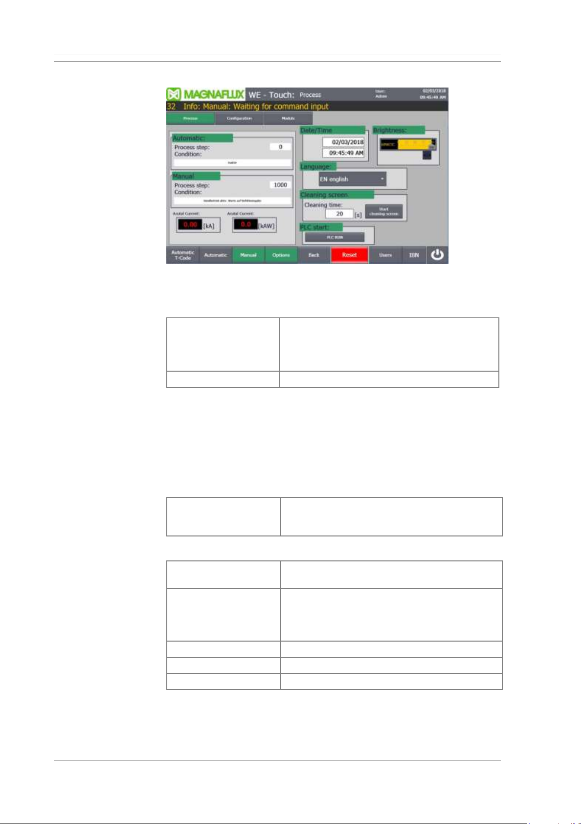
3.3.6 “Options” screen
Settings and diagnosis
Display
The screen can be shown in Manual mode or Automatic mode.
Options
Press the Options button at the bottom of the
screen.
→ Example at top: The Manual mode stays
active.
Back
Close screen and display the last displayed image.
Sequencer
The control works in the two operating modes manual mode and automatic
mode with step chain technology. The process is structured into individual
steps, which are run through one after the other depending on so-called
switching conditions.
The current step number and the condition for the next step can be used to
make a diagnosis in the event of a fault.
Digital displays actual
values
Display of the current magnetising currents of the
preselected magnetising circuits when
magnetisation is active (see step display).
Further input and selection fields and buttons
Date / time
Settings for the current date and time
(displayed in header).
Brightness
Brightness of display.
Tip: Reduce the brightness of the display during
workpiece inspections in the darkening cabin
under UV light.
Language
Selection of language at the user interface.
Back
Close screen and display the last displayed image.
Cleaning screen
Disable touch operation to clean the screen surface.
Page 46
Basis of operation UNIVERSAL WE TOUCH TCODE
46 / 85 MX UWETOUCH_v.3
2019-05-03
Start PLC
Start machine control.
Only necessary if the PLC control is in STOP state.
We strongly recommend: Carefully determine the
cause of the STOP and take the necessary
measures.
Reset
Button lights up bright red: Fault detected and
message not acknowledged.
Touch the button: Stop the active sequence, e.g.
acknowledge demagnetisation and/or fault
message when the cause has been eliminated.
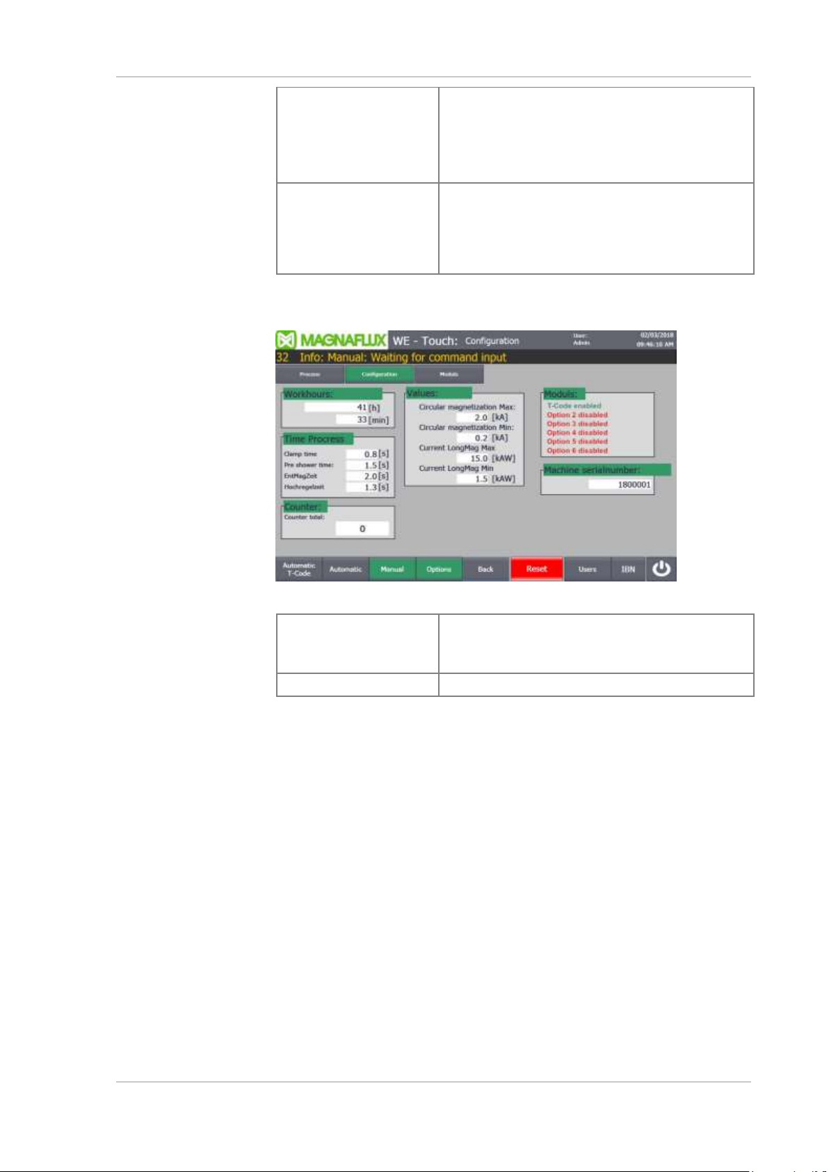
Options - Configuration
Options - Configuration
Configuration
To display the screen:
Open the Options screen and then tap the
Configuration button.
Back
Close screen and display the last displayed image.
Display of basic settings and limits of the machine. It is not possible for
machine operators to change the values.
Page 47
UNIVERSAL WE TOUCH TCODE Basis of operation
MX UWETOUCH_v.3 47 / 85
2019-05-03
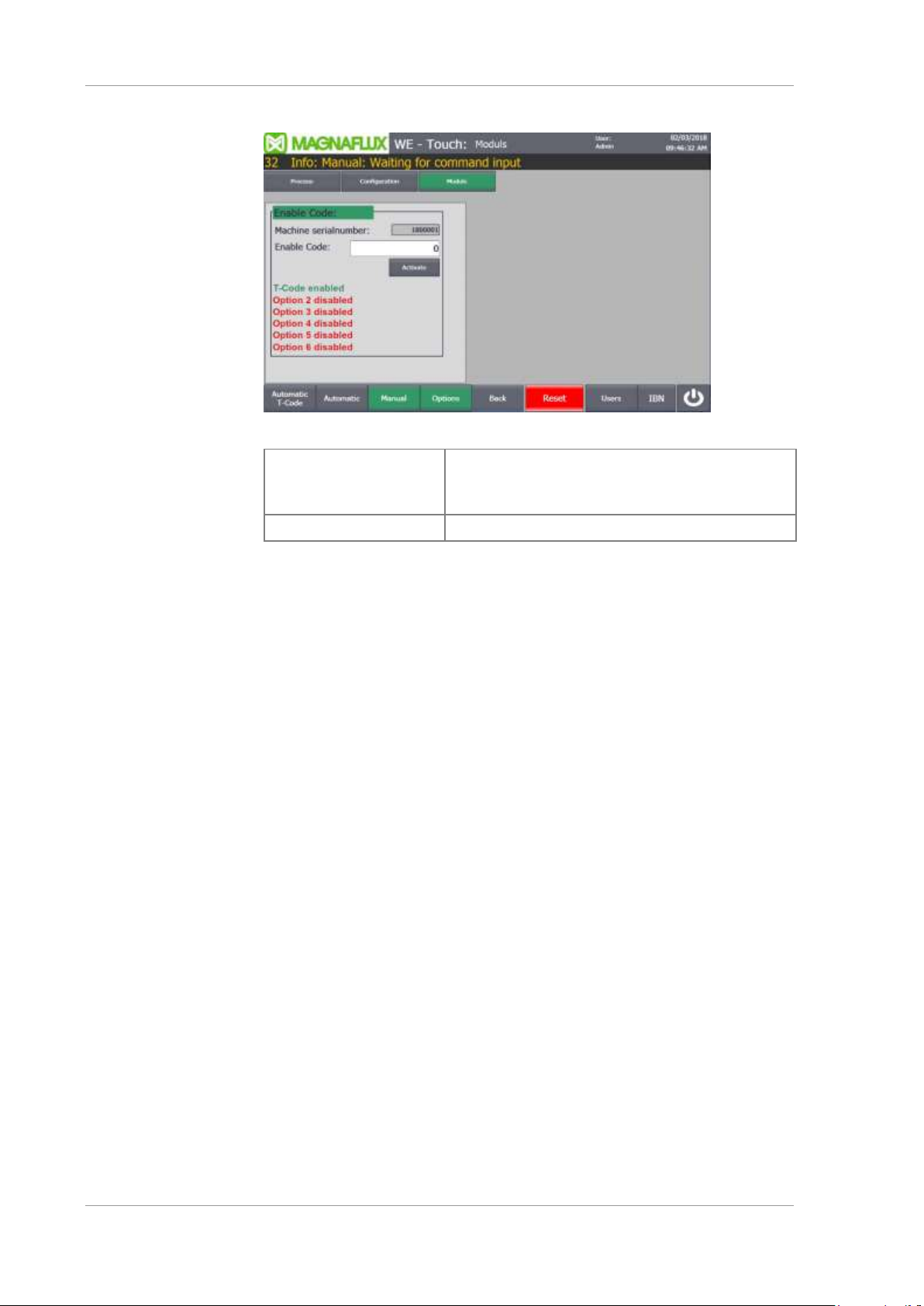
Options - Modules
Options - Configuration
Module
To display the screen:
Open the Options screen and then tap the
Module button.
Back
Close screen and display the last displayed image.
Display of the enabled function modules of the machine.
Activation of further modules is also possible on site by the machine operator
via an activation code.
If required, please contact MAGNAFLUX sales department. You will then
receive a unique unlock code associated with the machine number and the
desired module.
Page 48
Basis of operation UNIVERSAL WE TOUCH TCODE
48 / 85 MX UWETOUCH_v.3
2019-05-03
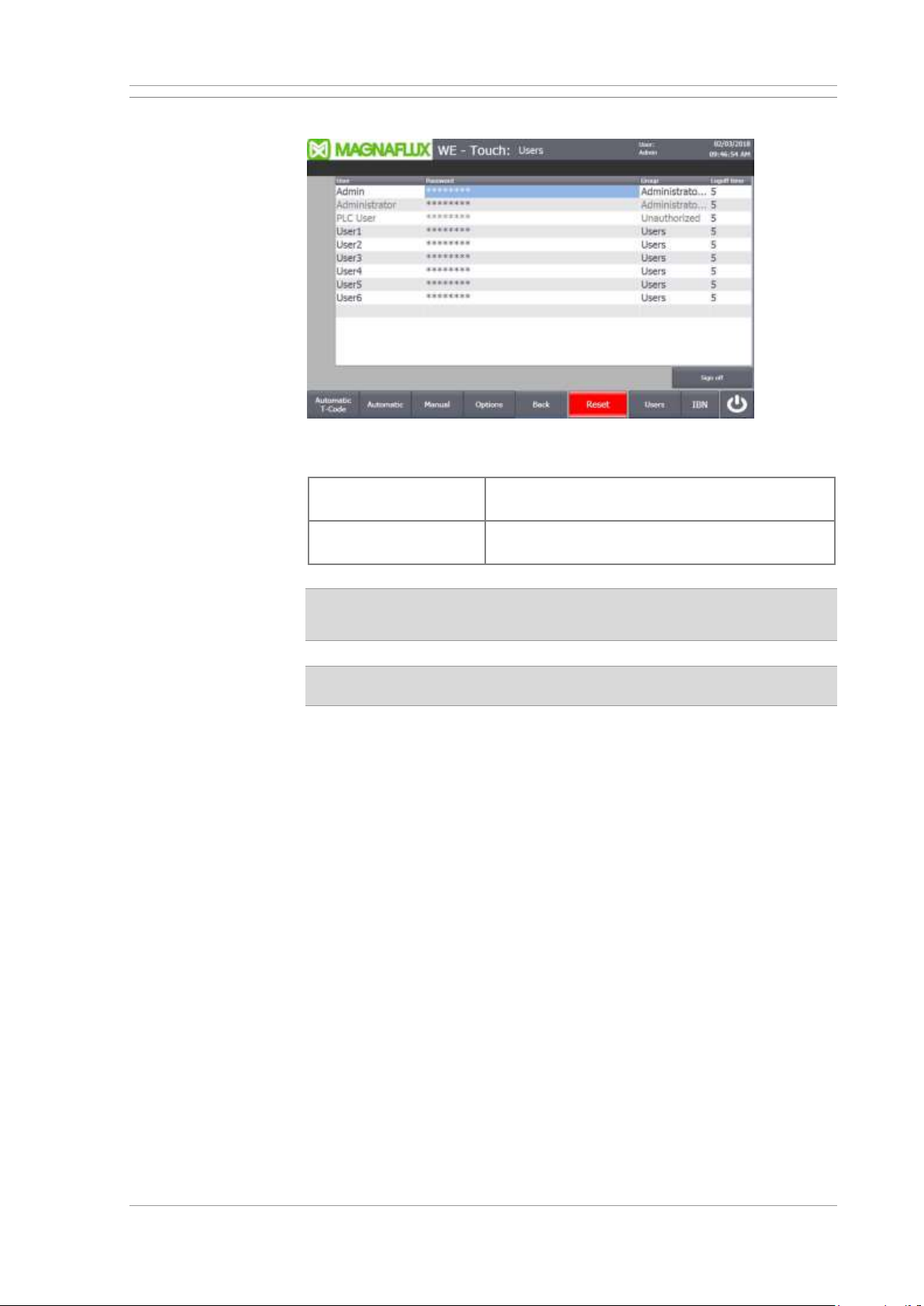
3.3.7 Screen “User Administration”
Display and setting options for limit values and specifications
Open
User
Press the User button at the bottom of the
screen.
Back
Close screen and display the last displayed
image.
Changes only possible after logging in as administrator!
If required, please contact Magnaflux service.
Before making any changes, it is essential to observe the notes in
chapter 4.6.
Page 49
UNIVERSAL WE TOUCH TCODE Basis of operation
MX UWETOUCH_v.3 49 / 85
2019-05-03
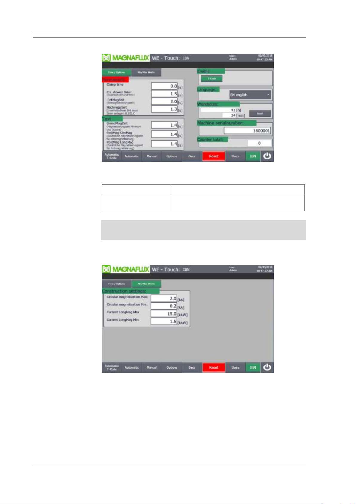
3.3.8 “Commissioning (IBN)” screen
Display and setting options for limit values and specifications
Open
IBN
Press the IBN button at the bottom of the screen.
Back
Close screen and display the last displayed
image.
The screen is only accessible after logging in as administrator!
If required, please contact Magnaflux service.
Min/Max values
Individual limit values for the magnetising currents
Page 50

Basis of operation UNIVERSAL WE TOUCH TCODE
50 / 85 MX UWETOUCH_v.3
2019-05-03
3.4 Switching the machine ON and OFF
3.4.1 Emergency shut-down
In addition to a controlled shut-down, the machine can be switched off
immediately, forced shut-down, in case of emergency.
• Immediately switch off the main switch during emergencies or when
damage on the electric system are detected.
• Attach a padlock and warning sign to the main switch.
• Notify a relevantly qualified service technician.
• Ensure that all hazards have been remedied before reactivating the
machine.
3.4.2 Before switching the machine ON
1
Remove unauthorised personnel from the vicinity of the machine.
2
Carry out a visual inspection of the entire machine.
3
Check the fill levels of lubricants and consumables.
4
Remove all workpieces from the machine.
5
Where available: Unlock all EMERGENCY STOP buttons.
6
Check the set-up of the machine.
3.4.3 Switching the machine ON
Procedure
1
Activate the compressed air supply.
2
Switch on the machine at the master switch.
3
Where available: Unlock the emergency stop button.
Page 51
UNIVERSAL WE TOUCH TCODE Basis of operation
MX UWETOUCH_v.3 51 / 85
2019-05-03
3.4.4 Reactivating the machine after an emergency stop
Only relevant if the machine is equipped with an emergency stop
button!
WARNING
Before reactivating the machine on after an emergency stop
• determine the cause for the emergency stop,
• eliminate any hazards,
• Remove workpiece from the machine as needed.
Procedure
1
Determine the cause for the EMERGENCY STOP. Check whether all
dangers have been eliminated.
2
Unlock the pressed emergency stop button. Depending on model, Turn
the button head one quarter-turn clockwise or pull the top of the button
upwards.
3
Activate the machine controls.
4
Select manual mode.
5
Move the machine to the home position. Remove workpiece from the
machine as needed.
6
Repeat the interrupted inspection sequence.
3.4.5 Switching off the machine
Procedure
1
Complete the inspection of a workpiece.
2
Remove the workpiece from the machine.
3
Move the machine to the home position.
4
Switch off main switch and compressed air supply.
5
In case of operational interruptions longer than 2 days: Dispose of test
media from the test fluid tank and clean the machine.
Page 52

Basis of operation UNIVERSAL WE TOUCH TCODE
52 / 85 MX UWETOUCH_v.3
2019-05-03
3.5 Select operating mode
Start screen for automatic operation
When the machine is switched on, the automatic mode is activated and the
associated image is displayed.
To switch to manual mode, click on the Manual button at the bottom of the
screen. The display then changes to the associated Manual mode screen.
Page 53
UNIVERSAL WE TOUCH TCODE Machine adjustments
MX UWETOUCH_v.3 53 / 85
2019-05-03
4 Machine adjustments
4.1 Filling the test liquid tank
The test liquid tank must be filled with appropriate test liquid before
operation. It is imperative that you read and comply with the manufacturer
instructions and data sheet provided.
If you have already added test liquid, verify the concentration and indication
capability of the test liquid before running the test operation. See also the
chapter “Maintenance”.
Procedure
1
Clean the machine before adding new test liquid.
2
Switch off the machine controls.
3
Open the cap on the test liquid tank.
4
Fill test liquid tank. Do not overfill the tank.
5
Replace the cap.
4.2 Overview of setting tasks
The following setting tasks are required for the machine:
• Set the distance between the sleeves. Position the tailstock with the right
sleeve in such a way as to ensure secure seating of the workpiece on the
supports and secure clamping.
• Conversion and adjustment of workpiece supports (workpiece-specific,
if necessary).
• Configure the magnetising parameters on the control panel.
4.3 Set the distance between the sleeves
WARNING
Very heavy workpieces can fall off the supports and cause severe injury
to personnel or material damage.
• Never move the tailstock with a workpiece in place.
• Do not adjust settings on the tailstock with a workpiece in place.
• Insert workpiece with utmost care and avoid impact shock on the
workpiece supports.
• Do not step underneath hoisted loads when inserting workpieces.
CAUTION
Parts of the tailstock and the cable harness of the high current cables may
pose a crushing hazard for hands and fingers.
• Do not reach into the area of the tailstock track rollers.
• Personnel is not permitted at the rear of the machine near the cable
harness which the tailstock is in motion.
Page 54
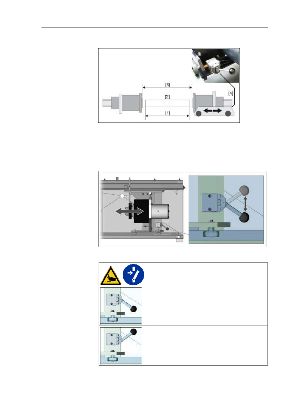
Machine adjustments UNIVERSAL WE TOUCH TCODE
54 / 85 MX UWETOUCH_v.3
2019-05-03
The mobile tailstock allows for large clamping widths. Adjust the position of
the tailstock to set the sleeve distance for the accommodation of workpieces.
Adjustment of the sleeve distance
[1]
Workpiece length
[2]
Workpiece
[3]
Distance between the sleeves
[4]
Clamping lever for fixing the cart
Manual valve for releasing the clamping device on the sleeve carriage
Switch off the main switch and compressed air
supply before any set-up work on the quills and
the quill carriage.
Sleeve carriage fixed (with spring force and
compressed air support)
Machine ready for clamping the workpiece and
subsequent magnetisation.
Clamping device of the sleeve carriage released.
Slide the sleeve carriage in the desired position
and tighten the clamping again.
Adjust the workpiece supports accordingly as
required.
Page 55
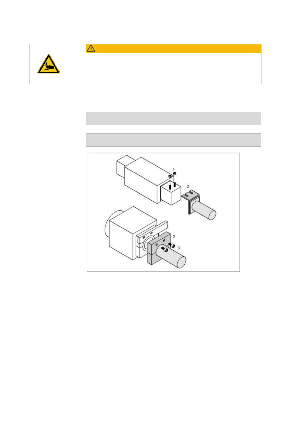
UNIVERSAL WE TOUCH TCODE Machine adjustments
MX UWETOUCH_v.3 55 / 85
2019-05-03
4.4 Replacing the magnetising mandrel (central conductor)
CAUTION
A heavy magnetising mandrel can crush hands and fingers.
• Hold the magnetising mandrel securely with both hands.
• Where a magnetising mandrel is to be lifted with hoisting equipment,
ensure that appropriate slinging gear is used for safe transportation.
• Remove unauthorised personnel from the vicinity of the machine.
Depending on the individual testing task and the size of the workpiece,
suitable magnetising mandrels (central conductors) for auxiliary flow can be
attached to the left spindle sleeve.
For the replacement of larger magnetising mandrels, 2 people and/or
appropriate hoisting equipment will be required.
The magnetising mandrel is attached to the sleeve by way of stud bolts
or threaded bolts depending on the model.
Mounting the magnetising mandrel (various models)
[1]
Clamping screw with counter nut
[2]
Magnetising mandrel
[3]
Fastening bolts
Page 56
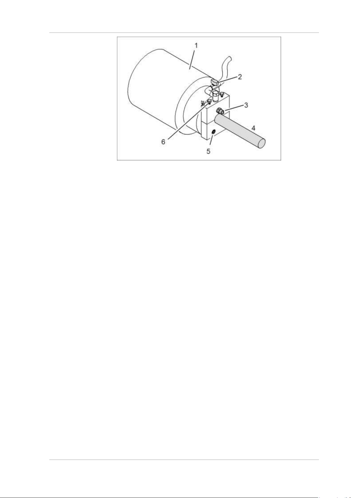
Machine adjustments UNIVERSAL WE TOUCH TCODE
56 / 85 MX UWETOUCH_v.3
2019-05-03
Example: Magnetising mandrel with spray nozzle for test liquid (option)
[1]
Left or right magnetising sleeve
[2]
Valve for test material (optional)
[3]
Spray nozzle for test material (optional)
[4]
Magnetising mandrel (central conductor)
[5]
Fastening bolt for holding the magnetising mandrel
[6]
Fastening bolts for the magnetising mandrel
Procedure
1
Move the machine to the home position.
2
Remove the workpiece from the machine.
3
Switch off the main switch and secure against unauthorised reactivation.
4
Dismount the magnetising mandrel (central conductor). Firmly hold the
magnetising mandrel (central conductor) and carefully release the
clamping screw on the rear of the sleeve plate. Firmly hold the
magnetising mandrel (central conductor) with both hands and pull it up
and away from the sleeve.
5
Mount the new magnetising mandrel (central conductor). Place the
magnetising mandrel (central conductor) on the sleeve. Tighten the
fastening bolts. Tighten the counter nut on the fastening bolts.
Page 57
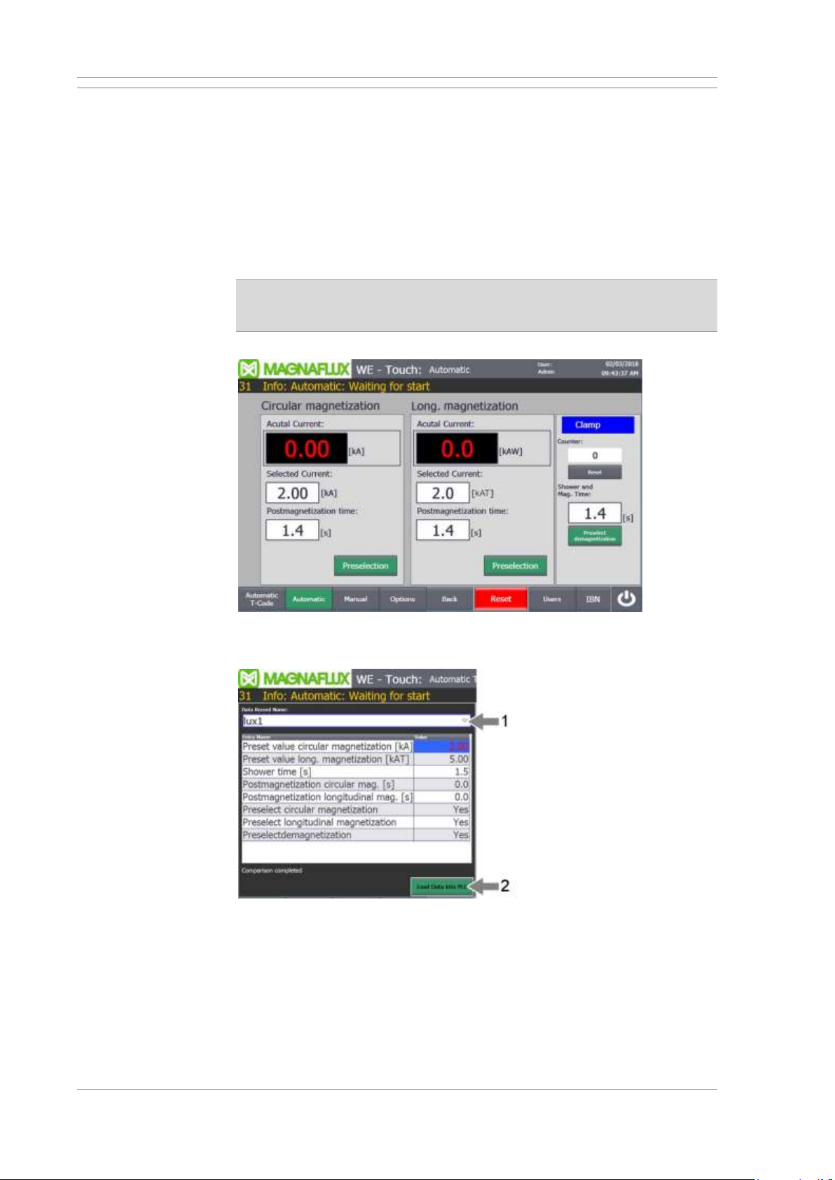
UNIVERSAL WE TOUCH TCODE Machine adjustments
MX UWETOUCH_v.3 57 / 85
2019-05-03
4.5 Setting the magnetising parameters
Manual or automatic operation without T-Code
Set the magnetisation parameters via the control panel in the images of the
respective operating mode. Ensure that sufficient field strength is achieved in
the workpiece. Check settings and crack detection using a workpiece with
a known fault.
Also refer to the description of the individual test sequence in Chapter 2.9
and the instructions for operating the machine in Chapter 3.
Current flow monitoring during magnetising will work only for nominal
values > 10% of max. value. Always enter a nominal value greater than
10%.
Operation in AUTO mode
Automatic mode with T-Code
On machines with T-code parameter memory, the settings of the
magnetisation parameters are stored in part-specific data sets.
Select a dataset: In the Automatic T-Code screen, select the desired data
set[1] and then press the Write data set to PLC [2] button.
Page 58
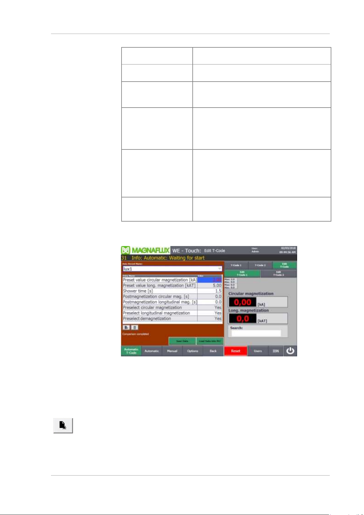
Machine adjustments UNIVERSAL WE TOUCH TCODE
58 / 85 MX UWETOUCH_v.3
2019-05-03
Description of setpoints
Preselection of current
flow
Switch the magnetisation circuit for axial (contact)
current flow or auxiliary flow on or off.
Preselection of yoke
magnetising
Switch the magnetising circuit for yoke (coil)
magnetising on or off.
Preselection of
demagnetising
Switch automatic demagnetising on or off.
With demagnetising active, the workpiece is
subsequently demagnetised after magnetising.
Current set points
Setpoints of the magnetising currents
• for magnetising circuit 1 in kA
• for magnetising circuit 2 in kAW
(current flow x number of turns (amp-turns)
Limit values: See Machine limits in chapter 2.
Setpoints for postmagnetisation times
Only in automatic operation:
• Duration of magnetisation after showering.
The spray function stops and remagnetising time
commences, once the spray time has elapsed.
The magnetising current is deactivated once the
remagnetising time has elapsed.
Shower and
magnetisation time
set point
Only in automatic operation:
Duration of magnetisation with showering.
Edit T-Code data record
Edit T-Code data record
1
Open the Automatic T-Code screen.
2
Press the Edit T-Code button.
The Edit T-Code screen appears
3
Select the desired data record in the data record name selection field.
→ The stored parameter values are displayed and can be edited.
4
Creating a new data set: Press the New data set button and enter a
unique name for the new data set.
5
Edit parameter values. Pre-select magnetising circuits, enter current
target values and magnetisation times.
Page 59
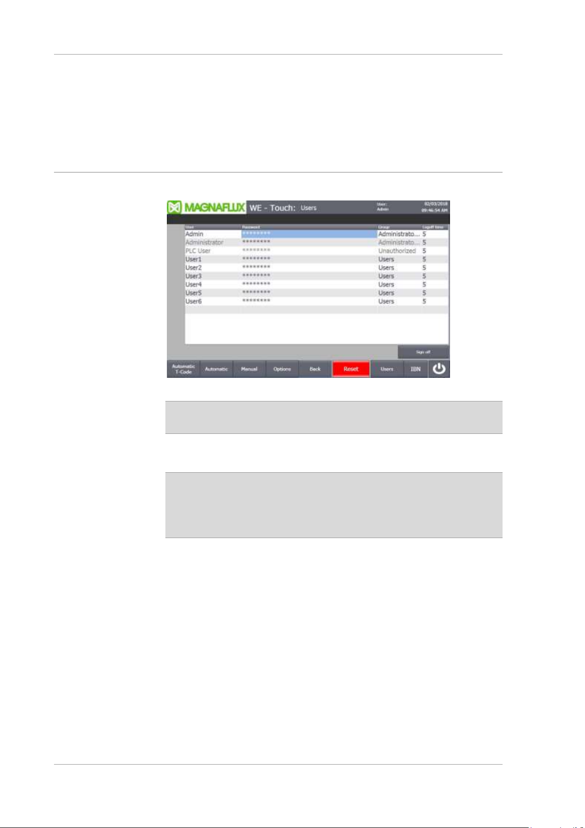
UNIVERSAL WE TOUCH TCODE Machine adjustments
MX UWETOUCH_v.3 59 / 85
2019-05-03
6
Save the data set and transfer it to the machine control system (PLC)
if required.
7
Touch the End editing button.
→ The Automatic T-Code screen appears.
8
If not already done, select the desired data set and transfer the
parameter values to the PLC.
4.6 Manage users
User Administration
Changes only possible after logging in as administrator!
If required, please contact Magnaflux service.
As administrator, the user names, passwords, groups and logout time can be
adjusted.
CAUTION: Entries in the user administration can be blocked by
mistake! A release is only possible through the service of the
manufacturer if
• the password for the administrator is changed and/or forgotten;
• the Admin group is changed to “User” or “unauthorized”.
Users of the Administrator groups and User can create and edit T-Code
recipes. No user login is required for checking workpieces and selecting
T-code data sets.
Page 60
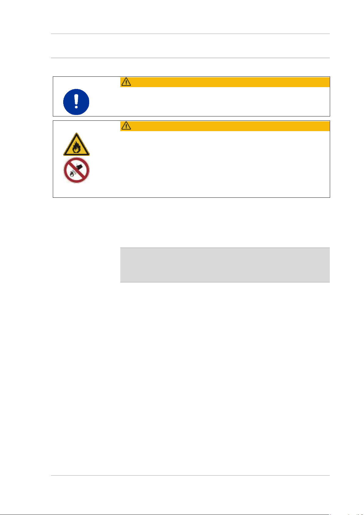
Inspecting workpieces UNIVERSAL WE TOUCH TCODE
60 / 85 MX UWETOUCH_v.3
2019-05-03
5 Inspecting workpieces
5.1 Safety instructions
CAUTION
Machine operation is reserved for trained personnel only. Read and comply
with the operating and safety instructions provided for the machine and
third-party components!
CAUTION
Test oils are highly flammable! Fire hazard!
• Only use flame-retardant test oils with a flash point > 100 °C.
• Keep all contact surfaces clean.
• Carefully adjust the contact points of the workpiece
(distance of the sleeves)
When using oily test liquids
• Have fire extinguishers at hand,
• ensure compliance with instructions provided by the test liquid
manufacturer!
The detectability of faults on workpieces decreases with diminishing quality
of the test liquid. The service life of test liquids depends on the inspection
task and the condition of the workpieces.
Check test liquids regularly and replace as needed!
Magnetising time limitation:
Max. magnetising time is limited to 30 seconds. A forced shut-down
will occur after that time. The machine will be locked for 1 minute.
A relevant error message is displayed on the control panel.
Page 61
UNIVERSAL WE TOUCH TCODE Inspecting workpieces
MX UWETOUCH_v.3 61 / 85
2019-05-03
5.2 Testing the workpiece in automatic mode
WARNING
High magnetic field strengths and powered components may cause
personal injury.
• Only one person must operate the machine and inspect the workpieces!
• No other personnel is permitted in the immediate vicinity of the machine
during magnetising.
• Remove unauthorised personnel from the vicinity of the machine!
• Do not reach into the work area of the machine during operation.
Also see description of the machine in Chapter 2 especially proper use
and the description of the sequences in Chapter 2.9.
Ensure the correct set-up of the machine before commencing a workpiece
test; in particular, check the settings for the magnetising parameters.
Requirements
• Machine is switched on and set-up in accordance with the workpiece
type.
• Machine is in home position.
• Test liquid tank is correctly filled with suitable test liquid.
• Where available: UV panel lamp switched on and at operating
temperature.
Procedure
1
Select the operating mode and associated screen.
Note: Automatic T-Code is only possible when the T-Code option is
available.
2
Check the machine set-up, especially the magnetisation parameters
and the demagnetisation preselection.
3
Insert workpiece.
4
Start the magnetising cycle. Depending on the design of the clamping
devices, actuate the foot switch or two-hand control until the status
display for clamping changes to green.
→ The workpiece is clamped between the sleeves.
→ The magnetising cycle starts, spraying and magnetising commence.
→ After the shower time has elapsed the showering switches of.
Remagnetisation time is started.
→ The sleeves relax, once magnetising is complete.
5
Remove the workpiece from the machine and evaluate under the
UV light.
Page 62
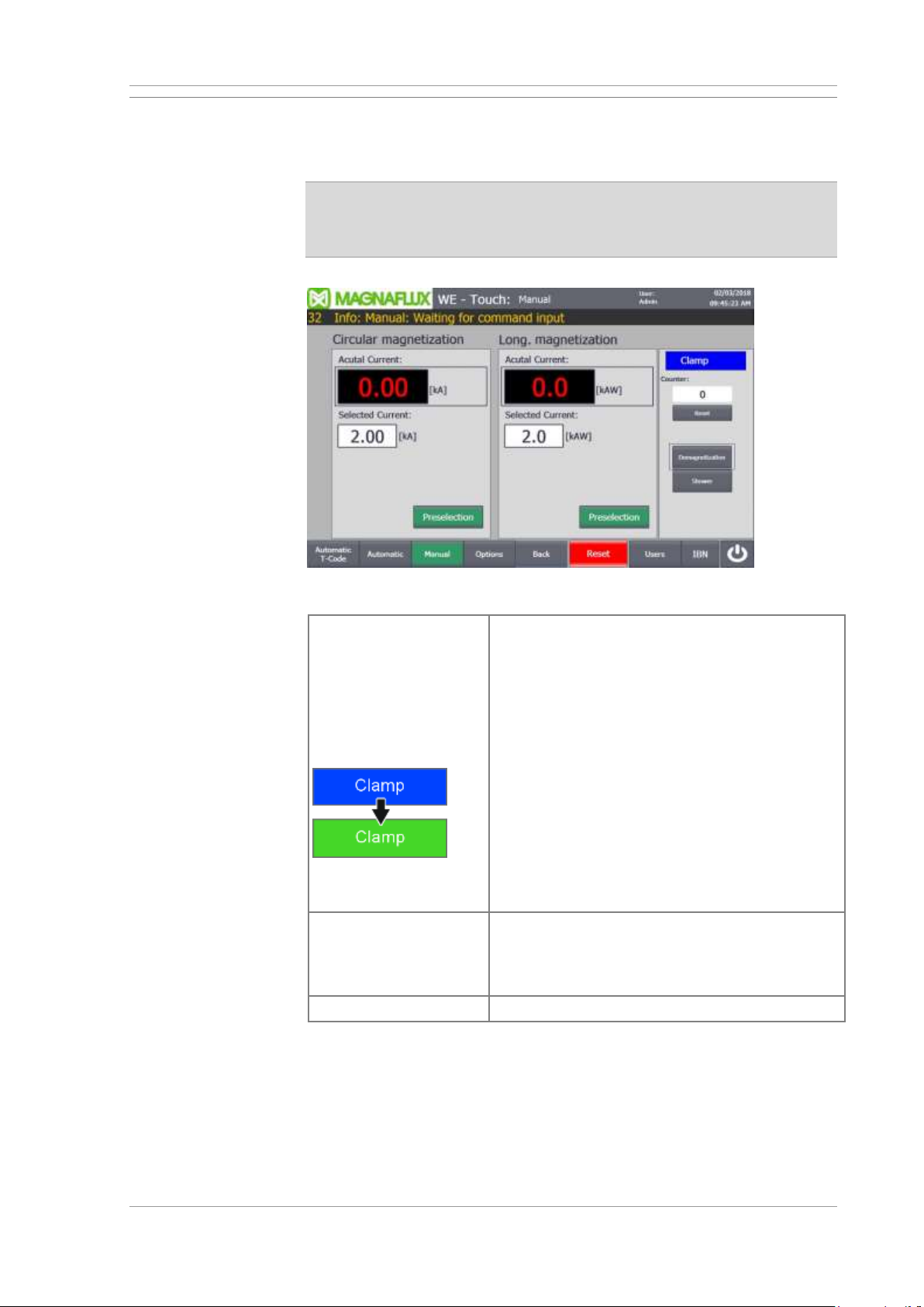
Inspecting workpieces UNIVERSAL WE TOUCH TCODE
62 / 85 MX UWETOUCH_v.3
2019-05-03
5.3 Manual mode
The workpiece can be magnetised or demagnetised in manual mode at any
time independent of the pre-set spray or remagnetising time.
Note on magnetising: Magnetising time must not exceed max.
activation time. A fault will be generated, once a magnetising time
of 30 seconds is exceeded. Magnetising will be locked for 1 minutes
(cool-down time).
Operation in MANUAL mode
Spraying and
magnetising
Select the magnetising circuit required and set the
nominal values for the magnetising currents.
Insert workpiece.
Make sure that the cock of the hand hose is
closed or that the hose is in the tub. To switch on
the shower facility.
Clamp workpiece and check magnetisation.
Depending on the design of the clamping devices,
actuate the foot switch or two-hand control until
the status display for clamping changes to green.
→ The workpiece is clamped between the
sleeves.
→ The magnetising current remains active as
long as the switch is actuated.
Demagnetising
Press and release the Demagnetise button on the
control panel for a few seconds.
The workpiece is magnetised and then
demagnetised.
Releasing
Activate the pedal switch or two-handed control.
Page 63
UNIVERSAL WE TOUCH TCODE Inspecting workpieces
MX UWETOUCH_v.3 63 / 85
2019-05-03
5.4 Replacing the test liquid
WARNING
Powered components in the area of the lifting equipment may snag and
crush extremities. Severe injury hazard! Before accessing the dug-out:
• Remove workpiece from the lifting equipment
• Lower lifting equipment into its home position
• Deactivate master switch and secure against unauthorised reactivation
Never close grille as long as personnel is present inside the dug-out!
Dirt particles washed off the workpieces by the test liquid will collect in the
test liquid tank. Contaminated test liquid will impair crack detection.
Procedure
1
Completely evacuate and clean test liquid tank.
2
Refill the tank with fresh test liquid. Select the quantity according to the
specifications on the test liquid packaging.
3
Add the specified amount of water.
4
Mix test liquid and water thoroughly.
5
Close the stopcock for the hand-held hose.
6
Dispose of the old test liquid according to regulations.
Page 64
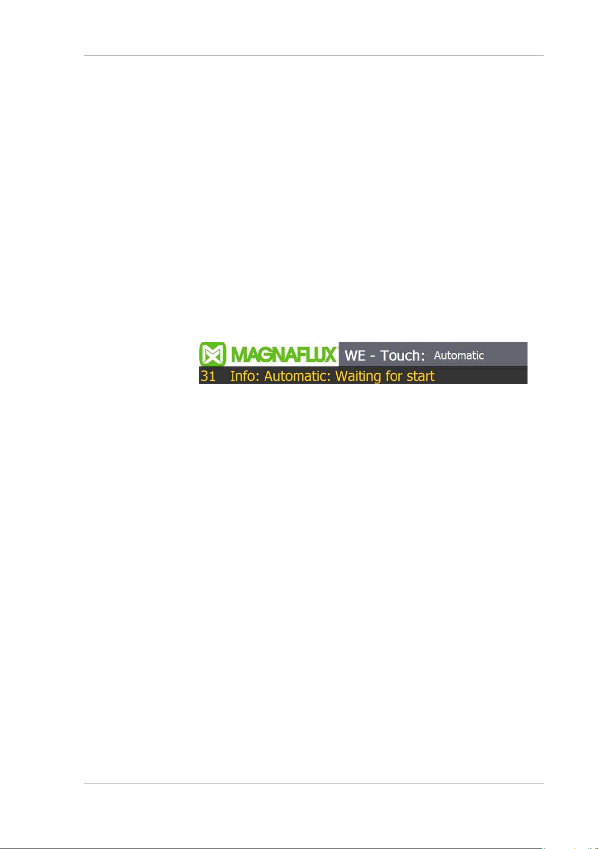
What to do in the event of a fault UNIVERSAL WE TOUCH TCODE
64 / 85 MX UWETOUCH_v.3
2019-05-03
6 What to do in the event of a fault
Establish a safe condition
The machine will be automatically brought to a safe condition and testing
operation is stopped if the controls detect a fault.
There are, however, a number of faults and errors that cannot be detected
by the controls, or it may no longer possible to establish an entirely safe
machine state.
Should a hazardous situation arise, then immediately
• press the emergency stop button (if fitted);
• deactivate main switch;
• if necessary, secure the main switch against reactivation
• attach a warning sign to the machine.
Investigate the cause
Detected malfunctions are displayed in the message list on the status bar as
plain text.
Tap on the message line to display an overview of the messages. You can
also acknowledge the messages once the cause has been eliminated.
Display of messages
Notify as required
• trained service personnel authorised to carry out repairs
• the customer service department of the manufacturer.
Page 65

UNIVERSAL WE TOUCH TCODE Machine cleaning
MX UWETOUCH_v.3 65 / 85
2019-05-03
7 Machine cleaning
Clean the machine
• when switched off,
• using either spent test liquid, and/or water and a hose with a low pressure
spray nozzle;
• never use compressed air or solvents,
• always clean the machine before replacing the test liquid.
7.1 Clean the magnetising station
Procedure
1
Convey the workpiece away from the lifting equipment.
2
Clean all components (with the exception of sensors!) in the work area
of the machine with the hand-held shower or the hand-held hose.
3
When cleaning with water from an external source:
The cleaning water will run into the test liquid tank. Make sure that
the tank does not overflow.
4
Rub off stubborn dirt with a cloth. Do not use any metallic tools.
5
Drain and clean the test liquid tank.
6
Fill with fresh test liquid.
7.2 Clean the test liquid tank
Clean the test liquid tank each time the test liquid is replaced.
Procedure
1
Drain the test liquid tank fully using the test liquid pump.
2
Deactivate main switch.
3
Remove the cover and the test liquid pump from the test liquid tank.
4
Pour some water into the tank.
5
Clean the tank with a cloth. Do not use any tools.
6
Empty the tank again completely.
7
Replace the test liquid tank cover and test liquid pump.
8
Clean the dirt screen inside the tank cover. Replace screen if you
detect any damage. Magnaflux Order No. 62600-009126.
Page 66
Maintenance UNIVERSAL WE TOUCH TCODE
66 / 85 MX UWETOUCH_v.3
2019-05-03
8 Maintenance
Maintenance includes all technical and administrative actions to maintain
and re-establish the machine's functional state.
Carry out the described tasks periodically at the intervals specified in the
inspection and maintenance schedule.
8.1 Maintenance schedule
Overview maintenance intervals
Interval
Period
Operating hours
1
daily
8 h
2
weekly
40 h
4
quarterly
500 h
Carry out the maintenance tasks at the intervals recommended above.
Adjust the maintenance intervals according to individual usage conditions as
needed.
Safety-relevant parts of the machine are designed for a service life of
10 years. After 10 years, the operating company is required to have a
safety inspection carried out by the manufacturer.
Inspection and maintenance interval 1
Entire machine
Carry out visual inspection. The machine must
not be used if any damage is detected; notify
service personnel as needed.
Safety equipment
Where available: Check the EMERGENCY
STOP function. Control current and
magnetising current must deactivate and all
drives must stop immediately when the
EMERGENCY STOP button has been
pressed.
Checking the two-handed control. After
releasing the push button the clamping
movements have to stop immediately.
Test liquid
Check test liquid concentration and display
ability, replace as needed.
Test liquid system
Clean the testing liquid tank and dirt collection
sieve in the return flow.
Page 67
UNIVERSAL WE TOUCH TCODE Maintenance
MX UWETOUCH_v.3 67 / 85
2019-05-03
Inspection and maintenance interval 2
Entire machine
Clean with a mild industrial detergent, no solvents
or acids and alkaline solutions.
Workpiece supports
Visual check for damage. Replace any damaged
parts as needed.
Magnetising workpiece
Check magnetising by measuring the field
strength in the workpiece.
Magnetising contacts
Clean magnetising contacts with steel wool and
coat with contact grease.
UV lamps (where
included in the system)
Measure light intensity; visual check of the filter
disk. Replace defective filters as needed.
Pneumatic
maintenance unit
Evacuate compressed air/water separator; top up
oil in proportional oiler (if present)
Inspection and maintenance interval 4
Magnetising devices
Disconnect the high-current cables, clean the
contact points, and coat with contact grease.
Control cabinet and
transformer cabinet
Clean filter; replace filter mat as needed.
Page 68

Maintenance UNIVERSAL WE TOUCH TCODE
68 / 85 MX UWETOUCH_v.3
2019-05-03
8.2 Inspection instructions
8.2.1 Where available: Checking the EMERGENCY STOP button
Procedure
1
Activate the controls.
2
Press the EMERGENCY STOP button.
→ The control system must deactivate immediately.
3
Where available: Repeat steps 1 and 2 for each EMERGENCY STOP
button.
4
Deactivate the machine immediately and secure main switch against
unauthorised reactivation if one of the EMERGENCY STOP buttons
does not function correctly. Notify maintenance personnel.
8.2.2 Where available: Checking the two-handed control
Procedure
1
Activate the controls.
2
Select manual mode.
3
Clamp the clamping device using the two-hand switching.
4
Relax the clamping device. Press pedal switch for this.
5
Press both push buttons of the two-hand control one after the other.
→ No pneumatically driven movement is allowed.
6
Actuate two-hand control and release a push button during movement.
→ The movement must be stopped immediately.
Page 69
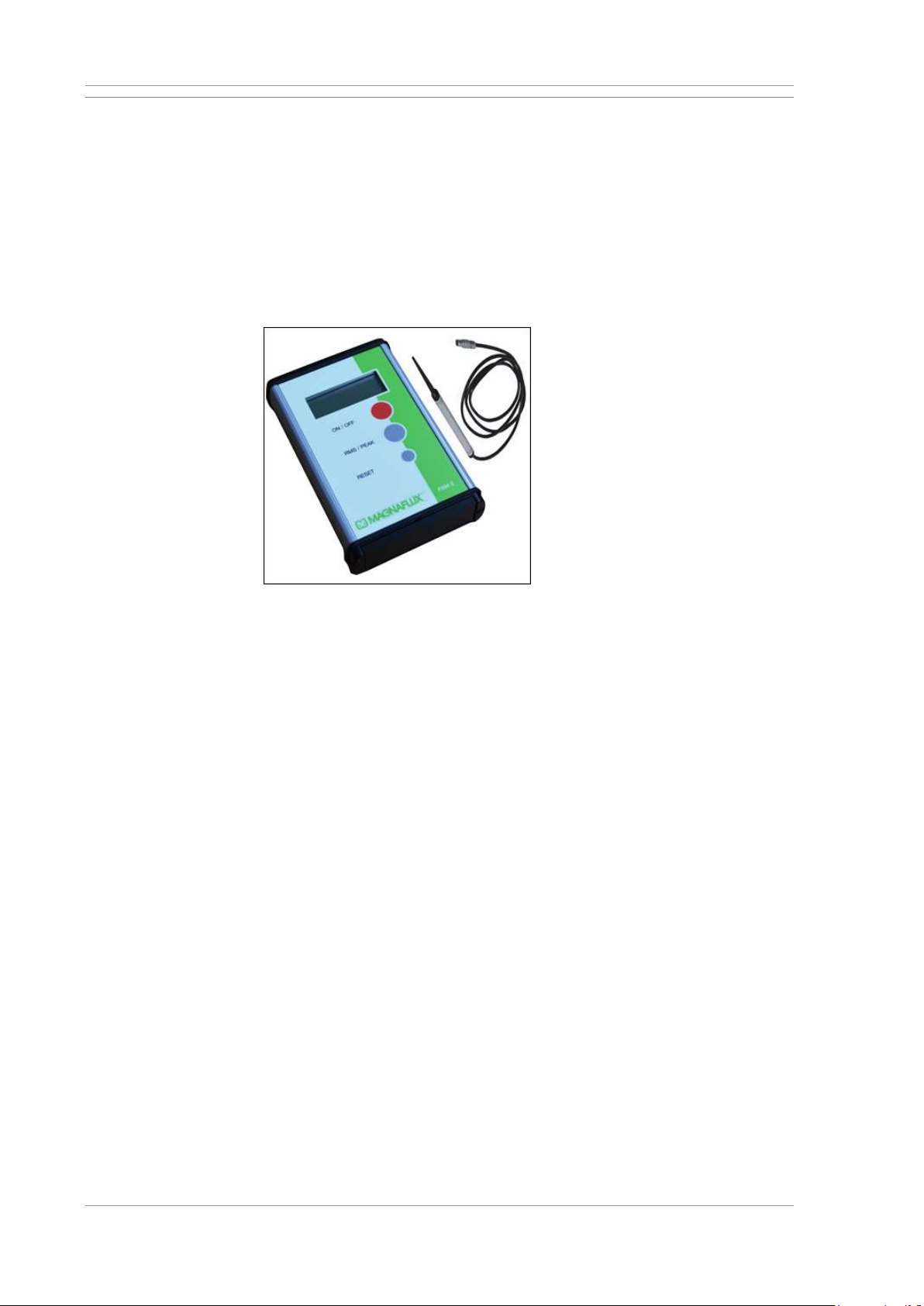
UNIVERSAL WE TOUCH TCODE Maintenance
MX UWETOUCH_v.3 69 / 85
2019-05-03
8.2.3 Measuring the magnetising field strength
The intensity and characteristics of the magnetic field are important
parameters for magnetic particle inspection. Check magnetising when
setting up the machine for new workpieces.
The tangential field strength measurement instrument FSM-2 is used for
tangential measurements of the magnetic field strength. The display of the
FSM-2 can be switched to show the field strength in A/cm as an actual or
peak value.
For more information about the FSM-2: See documentation provided by the
manufacturer.
Tangential field strength measurement instrument FSM-2
Requirements
Tools required
• Tangential field strength measurement instrument FSM-2,
Magnaflux Order No. 133 032.
Procedure
1
Magnetise workpiece.
2
Place measuring probe on the workpiece.
3
Read magnetic field strength in A/cm on display.
Page 70
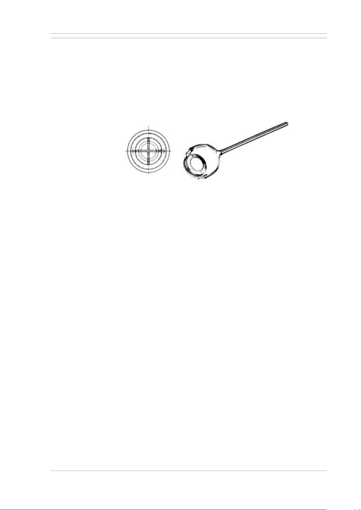
Maintenance UNIVERSAL WE TOUCH TCODE
70 / 85 MX UWETOUCH_v.3
2019-05-03
8.2.4 Magnetising testing
Professor Berthold's test block is a simple test device for determining display
sensitivity during magnetic particle inspections, as well as the directionality
of the magnetic field.
The test device consists of a flat, remanence-free circular shield into which a
soft-iron cylinder is inserted. The soft iron consists of 4 sectors. These sectors
are separated by non-magnetising slits and form 2 perpendicular air gaps.
For more information about the test block: See documentation provided by
the manufacturer.
Professor Berthold's test block
Requirements
Tools required:
• Prof. Berthold's test block, Magnaflux Order No. 135 005.
Procedure
1
Magnetise workpiece.
2
Place test block on the workpiece.
→ Some of the field lines will flow through the soft-iron core of the test
block.
3
Wet the test block with test liquid.
→ Depending on field directionality, one or the other of the gaps of the
crosswise slits will be mapped on the test block.
→ The magnetic field runs perpendicularly to the gap mapped.
4
Turn the base of the test body's enclosure in such a way that the
distance to the workpiece increases. Turn until the magnetic particle
indication disappears. The greater the distance, the more sensitive the
display achievable with the test method.
Page 71
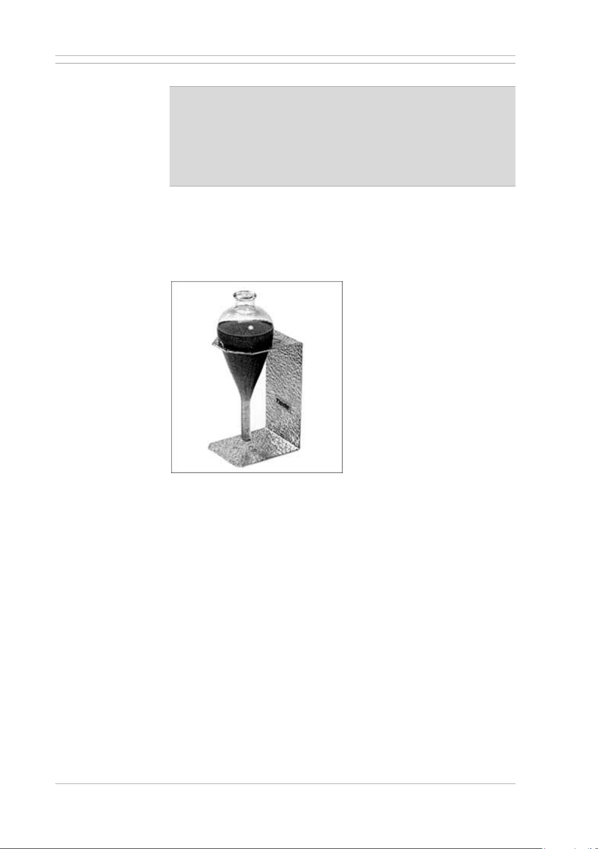
UNIVERSAL WE TOUCH TCODE Maintenance
MX UWETOUCH_v.3 71 / 85
2019-05-03
8.2.5 Checking the test liquid concentration
The detectability of faults on workpieces decreases with diminishing
quality of the test liquid. The service life of test liquids depends on the
test type and the condition of the workpieces.
The indicating capability of the test liquid must therefore be verified
periodically. Replace the test liquid as needed!
Magnetic particle suspensions in pump circuits must not be tested using
the ASTM bulb. Dirt particles in the test liquid will falsify indications.
For optimised fault detection on workpieces, the test liquid concentration
must exactly match manufacturer specifications.
Checking the test liquid concentration
• after replacing the test liquid,
• after prolonged work interruptions.
ASTM bulb
Requirements
Tools required
• ASTM bulb, Magnaflux Order No. 135 015.
Procedure
1
Fill the ASTM bulb with freshly mixed test liquid.
2
Allow the ASTM bulb to settle for 30 minutes.
3
Check the settled magnetic particles against the graduation marks on
the ASTM bulb.
Page 72
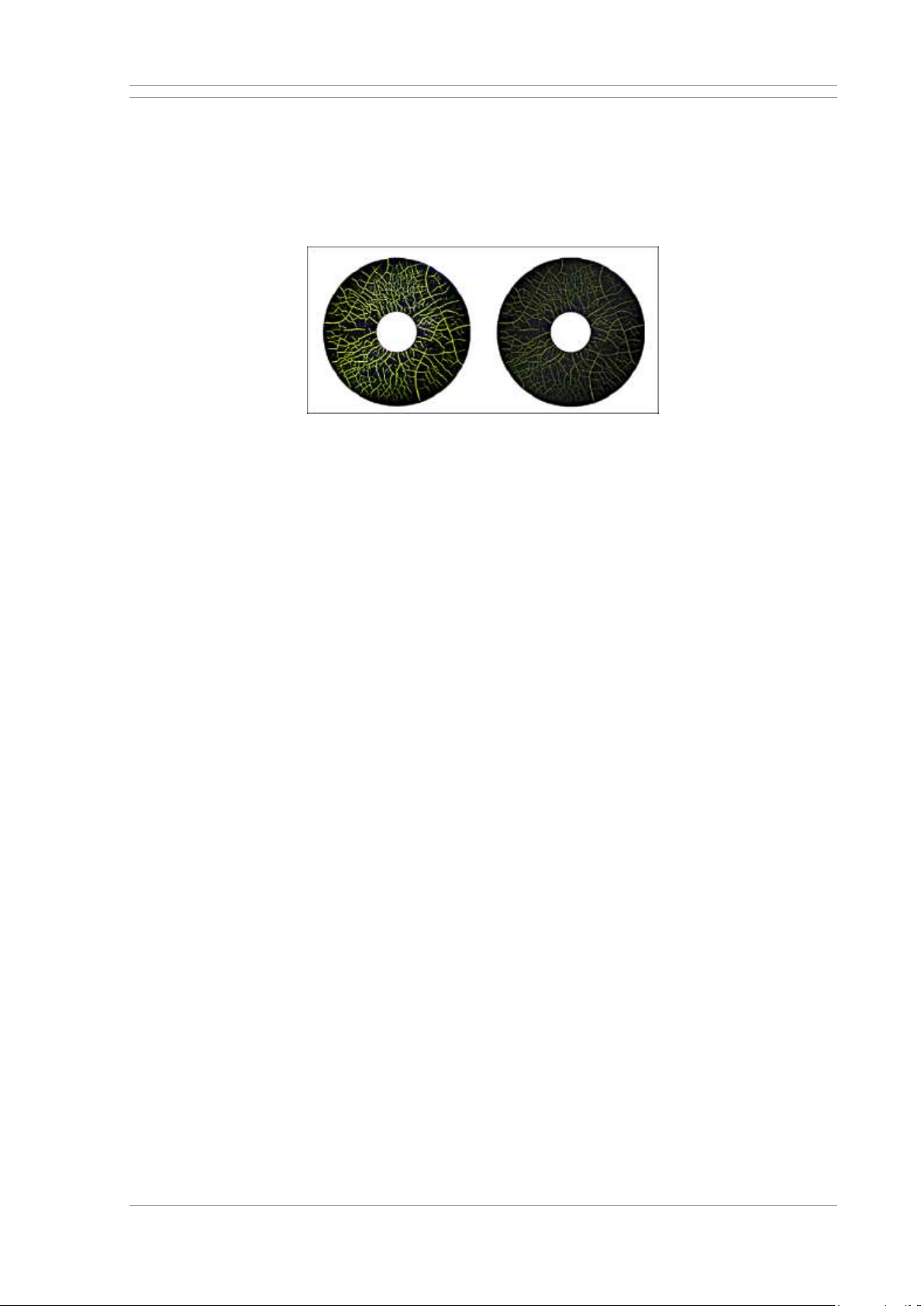
Maintenance UNIVERSAL WE TOUCH TCODE
72 / 85 MX UWETOUCH_v.3
2019-05-03
8.2.6 Verifying the test liquid indication capability
The detectability of faults on workpieces decreases with diminishing quality
of the test liquid. The service life of test liquids depends on the inspection
task and the condition of the workpieces.
The indicating capability of the test liquid must therefore be verified
periodically. Replace the test liquid as needed!
Comparison block with fault pattern
• Image on the left: Good indication capability of the test liquid
• Image on the right: Test liquid spent
Requirements
Tools required
• Comparison block 1, in accordance with EN ISO 9934-2
Magnaflux Order No. 135 011.
Procedure
1
Spray test block evenly with test liquid.
2
Hold the test block by the edge and inspect under a UV light.
3
Compare indications on the test block with the illustrations in the test
block manual.
Page 73
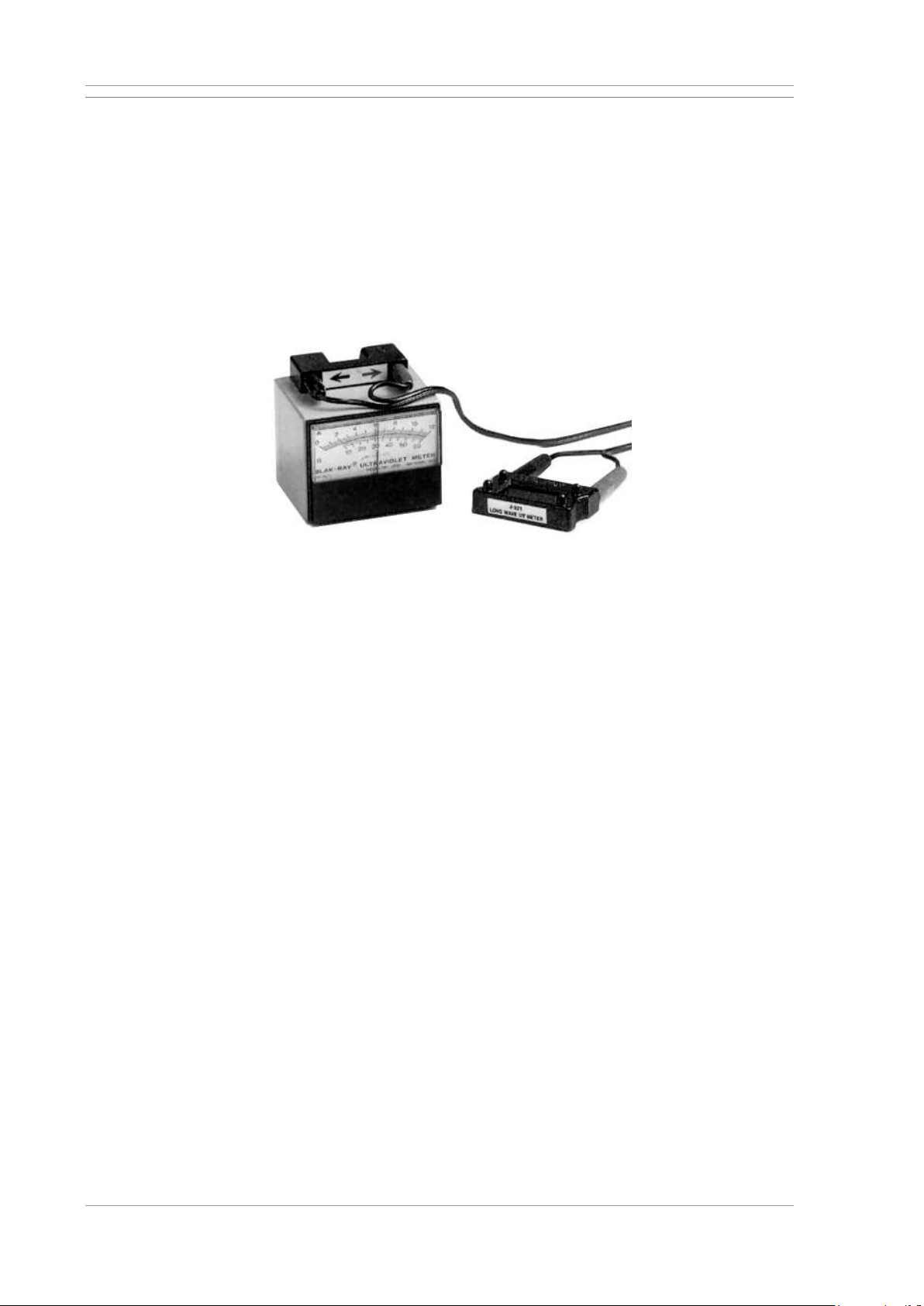
UNIVERSAL WE TOUCH TCODE Maintenance
MX UWETOUCH_v.3 73 / 85
2019-05-03
8.2.7 Checking the UV Intensity
The detectability of workpiece defects can be considerably increased by
fluorescent test liquid and UV light. The light intensity of the UV lamp plays
a significant role.
Light intensity can decrease noticeably with increasing age of the lamp. The
light intensity of all UV lamps must therefore be checked periodically, and
lamps be replaced as needed.
The light intensity should be approx. 1000 µW/cm². Deviations from this guide
value may occur depending on individual test conditions and ambient light.
UV measurement instrument J221
Check the of the UV light intensity with manual UV meter readings.
Requirements
Tools required
• J221 UV meter, Magnaflux Order No. 134 001.
Procedure
1
Switch on the UV lighting.
2
Wait about 10 minutes for the lamp to reach max. light intensity.
3
Hold the sensor of the UV meter under the lamp.
4
Check the intensity reading.
Page 74
Maintenance UNIVERSAL WE TOUCH TCODE
74 / 85 MX UWETOUCH_v.3
2019-05-03
8.3 Maintenance instructions
8.3.1 Drain the compressed air water separator
Depending on the quality of the compressed air, more or less water will
collect in the water separator of the compressed air maintenance unit.
Check the fill level of the water separator:
• periodically in accordance with the maintenance schedule,
• at intervals determined from experience.
Empty the tank as needed.
Check the fill level of the water separator in the compressed air maintenance
unit
• periodically in accordance with the maintenance schedule,
• at intervals determined from experience.
Procedure
1
Hold a container under the compressed air maintenance unit.
2
Open the drain screw on the water separator.
3
Drain condensate completely.
4
Close the drain screw.
8.3.2 Filling oil into the dosing oiler
CAUTION
Spilled oil may result in injuries due to slipping.
Pay attention to cleanliness when handling oil.
• Wipe up any spillage immediately.
• Dispose of oily rags according to regulations.
The dosing oiler enriches the compressed air with oil. Read chapter
“Technical data” for oil specifications.
1
Periodically check the oil fill level in the container on the compressed air
maintenance unit.
2
If the oil level is below the minimum mark: Detach the oil container
3
Top up with oil to the max. mark.
4
Carefully replace the oil container.
Page 75
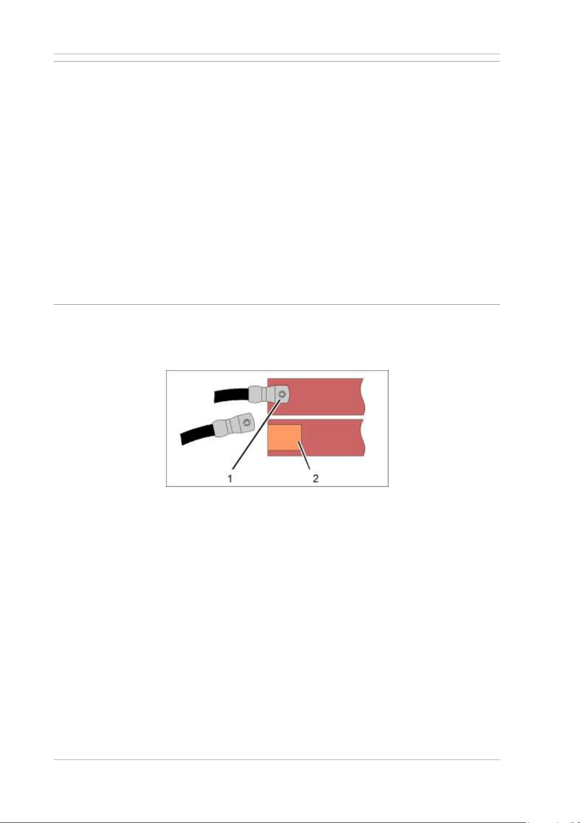
UNIVERSAL WE TOUCH TCODE Maintenance
MX UWETOUCH_v.3 75 / 85
2019-05-03
8.3.3 Cleaning the magnetising contacts
Dirty or corroded magnetising contacts, e.g. the folding coil, will lead to
excessive transition resistances at the contact points.
The magnetising contacts must therefore be cleaned regularly. Maintenance
cycles are strongly dependent on use. Adjust maintenance intervals
according to your own experience.
Requirements
Tools required:
• Contact grease Tungrease VC563,
MAGNAFLUX Item No. 71100-140483
• Steel wool, medium fine
Procedure
1
Switch off machine and secure against unauthorised reactivation.
2
Clean the contact points with steel wool to a metallic bright finish.
3
Apply a thin coat of contact grease to the contact points.
8.3.4 Cleaning the contacts of the high-current connections
Clean all connection points (current transitions) between the high-current
transformer, high-current cable, high-current switch and magnetising units
regularly.
High-current connection
[1]
High-current connection
[2]
Contact area
Requirements
Tools required:
• Contact grease Tungrease VC563,
MAGNAFLUX Item No. 71100-140483
• Steel wool, medium fine
Procedure
1
Switch off machine and secure against unauthorised reactivation.
2
Loosen the connections on the high-current cables.
3
Clean the contact points with steel wool to a metallic bright finish.
4
Apply a thin coat of contact grease to the contact points.
5
Re-establish the connections.
Page 76
Machine transport UNIVERSAL WE TOUCH TCODE
76 / 85 MX UWETOUCH_v.3
2019-05-03
9 Machine transport
9.1 Transport preparation
1
Decommission the machine prior to transport.
2
Inspect the condition and load bearing capacity of the floor at the
intended installation location and along the entire transport route.
• The machine must only be installed on a level and firm surface.
• Comply with relevant local regulations for work spaces.
• Take note of the technical information provided for the machine.
3
Specify and mark the exact installation location.
4
Specify the transport route and remove possible obstacles.
5
Keep unauthorised personnel away from the transport route and
installation location. Cordon off these areas, if necessary.
9.2 Transport in original packaging
WARNING
Lifted loads can fall and result in severe injury or damage to material assets.
• Machines and machine components must only be lifted or transported
with appropriate lifting equipment suitable for the weight and dimensions
of the machine.
• Transport, disassembly and assembly of the system must only be carried
out by specifically trained personnel.
The machine is delivered in its original packaging on a pallet or crated, and
should be transported in the same condition as close as possible to the
installation location.
The machine in its original packaging is bolted to the pallet and secured with
straps. Machines must not be tipped over or tilted more than 10° from the
horizontal. Relevant warnings are attached in plain view to the packaging.
The gross weight of the machine including packaging is stated in the
shipping documents.
Procedure
1
Insert the forks of a suitable forklift into the transport pallet at the
marked positions.
2
Lift the machine slightly and with care.
3
Transport the machine close to the ground to the unpacking location.
4
Lower the machine carefully and slowly. Do not reach under the
machine.
Page 77

UNIVERSAL WE TOUCH TCODE Machine transport
MX UWETOUCH_v.3 77 / 85
2019-05-03
9.3 Unpacking the machine
1
Where available: Cut and remove shrink wrap.
2
Use a crowbar to open the crate.
3
The machine components are bolted to the pallet and secured with
straps. Unscrew the fastening bolts and carefully loosen the straps.
4
Lift small parts and accessories off the pallet by hand.
9.4 Machine transport
The machine cannot be transported in a ready-to-operate state. Machine
components, electric and pneumatic connections and safety features must
be removed for transport.
• Empty test liquid tank.
• Remove the workpieces from the machine.
• Disconnect the power supply.
Machine disassembly, transport and subsequent reassembly must only
be carried out by relevantly trained technicians.
Please contact the Magnaflux service department with any questions
you may have.
Transport instructions
• Take note of the instructions contained in the operating manual, the
general safety instructions, accident prevention regulations and local
requirements for transport.
• Secure the installation location against unauthorised access until all
safety features of the machine have been installed and are fully
functional.
Page 78

Machine transport UNIVERSAL WE TOUCH TCODE
78 / 85 MX UWETOUCH_v.3
2019-05-03
9.4.1 Transporting the magnetising station with a forklift
WARNING
Lifted loads can fall and result in severe injury or damage to material assets.
• Machines and machine components must only be lifted or transported
with appropriate lifting equipment suitable for the weight and dimensions
of the machine.
• Transport, disassembly and assembly of the system must only be carried
out by specifically trained personnel.
Requirements
• No workpiece in the machine.
• Machine in the home position.
• All moving parts are secured against movement.
• Main switch is off and all supply lines are disconnected.
• Test liquid tank is drained and detached from the magnetising station.
Mains cable of the test liquid pump is unplugged.
• Floor fastening bolts have been removed.
If the control cabinet is not permanently fixed to the machine:
• disconnect all cable connections between the control cabinet and the
magnetising station.
If the transformer cabinet is not permanently fixed to the machine:
• disconnect the high current connections between the transformer cabinet
and the magnetising station.
Procedure
1
Check and secure the transport route and remove possible obstacles.
2
Insert the forks of a suitable forklift as far as possible into the base.
The forks must project at least 20 cm (8 in) at the rear of the machine.
If necessary, use two forklifts to lift the machine.
3
Carefully lift the machine only a small distance off the ground. Ensure
centre of gravity adjustment! If necessary, correct the position of the
forks until the machine is securely supported by the forklift.
4
Transport the machine to the installation location as close as possible
to the ground.
5
Lower the machine carefully and slowly.
6
Transport the test liquid tank with a fork-lift truck or hoist. If necessary,
secure to a pallet.
Page 79
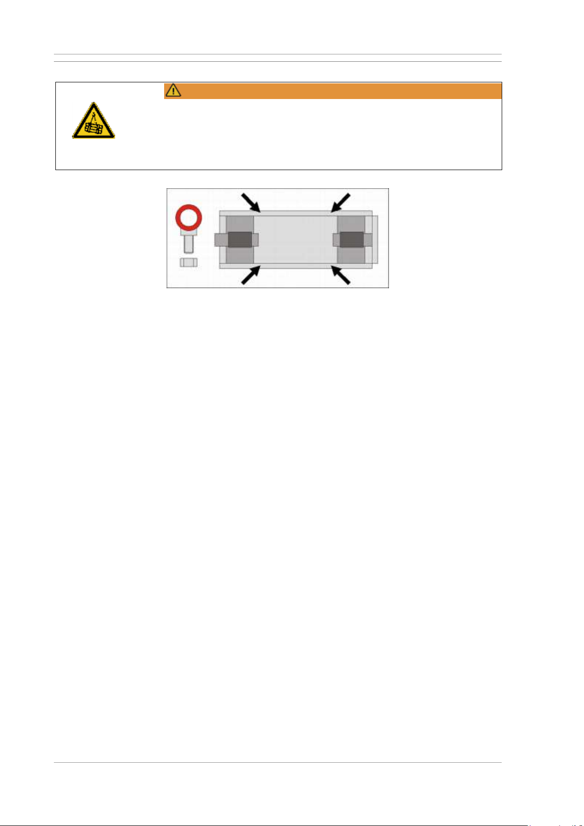
UNIVERSAL WE TOUCH TCODE Machine transport
MX UWETOUCH_v.3 79 / 85
2019-05-03
9.4.2 Transporting the magnetising station with a crane
WARNING
Lifted loads can fall and result in severe injury or damage to material assets.
• Machines and machine components must only be lifted or transported
with appropriate lifting equipment suitable for the weight and dimensions
of the machine.
• Transport, disassembly and assembly of the system must only be carried
out by specifically trained personnel.
Transport eyes on the machine
Requirements
• No workpiece in the machine.
• Machine in the home position. Tailstock with sleeve in right end position.
• All moving parts are secured against movement (straps).
• Main switch is off and all supply lines are disconnected.
• Test liquid tank is drained and detached from the magnetising station.
Mains cable of the test liquid pump is unplugged.
• Floor fastening bolts have been removed.
Procedure
1
Insert the transport eyelets into the bores on the lower frame and
fasten them with nuts. Check the transport eyes for secure fit before
transportation!
2
Attach the lifting equipment for transportation by crane to the transport
eyes marked red. Do not use other machine parts as slinging points.
Make sure that the lifting equipment does not run over protection
grilles or other attachments. Use one travelling crab each for the two
left and the two right transport eyes.
3
Carefully lift the machine only a small distance off the ground. Ensure
centre of gravity adjustment! If necessary, adjust the rope length so
that the machine is hanging straight from the crane.
4
Transport the machine to the installation location as close as possible
to the ground.
5
Lower the machine carefully and slowly.
7
Remove the transport lugs and transport locks.
Page 80

Setting up the machine and commissioning it UNIVERSAL WE TOUCH TCODE
80 / 85 MX UWETOUCH_v.3
2019-05-03
10 Setting up the machine and commissioning it
10.1 Setting up the machine
ATTENTION
Insufficient ventilation of control systems and motors may lead to
overheating.
• Place the machine where unrestricted air flow to the ventilation grilles is
ensured.
Installation must only be carried out by relevantly trained personnel.
Please contact the Magnaflux service department with any questions
you may have.
The correct set-up positions of the individual components is documented in
the installation plan.
Operate the machine
• in enclosed, dry spaces
• on a level surface only
Bolt the machine to the floor to achieve sufficient stability.
1
Set the machine down at it final location.
2
Mark the position of bore holes on the floor through the bores in the
attachment plates.
3
Move the machine slightly to the side.
4
Drill the holes into the floor and insert appropriate plugs.
5
Set the machine down at it final location.
6
Insert the bolts through the attachment plates into the floor plugs.
7
Tighten all bolts.
Page 81

UNIVERSAL WE TOUCH TCODE Setting up the machine and commissioning it
MX UWETOUCH_v.3 81 / 85
2019-05-03
10.2 Connecting the power supply
WARNING
High voltages can cause lethal electric shock and burns.
Electric connections are to be created
• in accordance with the wiring diagram and the information provided on
the type plate
• and must only be carried out by certified electricians,
• in compliance with applicable standards at the installation location.
• The device socket inside the control cabinet remains electrified even
after the main switch is switched off!
Power supply
Take note of the power supply data provided on the type plate and in the
switching diagram.
Note the following when connecting the power supply:
• On the construction side, only inert fuses must be used.
• Implement appropriately dimensioned lines in terms of length and power
supply conditions.
The cable entries are located on the underside of the control cabinet.
Compressed air supply
The machine requires a 6 bar (90 psi) pneumatic connection and a 7.2 NW
hose coupling for the compressed air supply.
The compressed air connection is located on the maintenance unit at the
rear of the magnetising unit.
Procedure
1
Feed the supply line into the control cabinet through the screw fitting on
the underside of the control cabinet.
2
Connect the supply line to the relevantly marked terminal strip in the
control cabinet.
3
Check the power supply:
• Voltage must match the type plate information
• Clockwise field rotation
4
Connect compressed air supply line to the maintenance unit via its hose
coupling.
5
Activate the compressed air supply.
6
Check proper seal of the connection.
7
Adjust the pressure via the pressure regulator on the maintenance unit.
See chapter Technical data.
Page 82
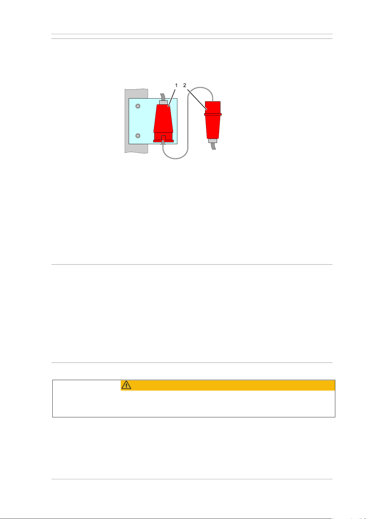
Setting up the machine and commissioning it UNIVERSAL WE TOUCH TCODE
82 / 85 MX UWETOUCH_v.3
2019-05-03
10.3 Connecting the test liquid pump
The test liquid pump is installed next to the test liquid tank and comes
equipped with a plug-in supply line. The socket [1] for the test liquid pump is
located in the dug-out that also contains the test liquid tank.
Plug and socket for test liquid pump supply
Procedure
1
Position the test liquid tank in its specified location. See machine
installation diagram.
2
Set the test liquid pump onto the tank.
3
Insert the line plug [2] for the test liquid pump into the socket [1].
4
Route the cable so that there is no tripping hazard and the cable cannot
be damaged.
10.4 Initial commissioning
The following tasks are required for initial machine commissioning:
• Check power supply.
• Fill test liquid tank.
• Check all functions.
• Set up the machine.
• Verify magnetising.
Detailed instructions on setting up the machines may be found in the
Preparations for operation section. Instructions for operation in manual and
automatic mode are provided in the chapter “Operation”.
10.4.1 Safety instructions
CAUTION
Initial machine commissioning may only be carried out by specifically trained
and certified personnel. Read and comply with the operating and safety
instructions provided for the machine and third-party components!
Page 83

UNIVERSAL WE TOUCH TCODE Setting up the machine and commissioning it
MX UWETOUCH_v.3 83 / 85
2019-05-03
10.4.2 Preparatory tasks
1
Remove unauthorised personnel from the vicinity of the machine.
2
Carry out a visual inspection of the entire machine.
3
Check power supply.
4
Check the fill levels of lubricants and consumables.
5
Set up the machine.
6
Close all safety gates and covers.
7
Where available: Unlock all EMERGENCY STOP buttons.
10.4.3 Checking functions and magnetising
Check machine function by way of a known faulty workpiece, or one that has
had a fault introduced purposely.
For setting-up, refer to Chapter 4.
Procedure
1
Move the machine to the home position.
2
Set up machine to receive the workpiece. Ensure that the distance of
the sleeves is set in such a way as to ensure the secure seating of the
workpiece on the supports.
3
Select manual mode. Set the mode selector switch in the 0 position.
4
Set current strengths and magnetising times. Switch demagnetising
OFF.
5
Insert the faulty workpiece.
6
Use hand-held shower to spray the workpiece with test liquid and
magnetise.
7
Visually inspect the workpiece for cracks and measure the field
strength.
8
Demagnetise workpiece in manual operation.
9
Measure the residual field strength in the workpiece.
10
Select automatic mode. Leave demagnetising function deactivated.
11
Use hand-held shower to spray the workpiece with test liquid and start
the magnetising cycle.
12
Visually inspect the workpiece for cracks and measure the field
strength.
13
Demagnetise the workpiece.
14
Measure the residual field strength in the workpiece.
Page 84

Decommissioning and disposal UNIVERSAL WE TOUCH TCODE
84 / 85 MX UWETOUCH_v.3
2019-05-03
11 Decommissioning and disposal
11.1 Safety instructions for decommissioning
WARNING
High voltages can cause lethal electric shock and burns.
Power terminals on drive controllers may continue to store dangerous
voltages up to 3 minutes after disconnecting.
Work on the electrical system
• and must only be carried out by certified electricians,
• in compliance with applicable standards at the installation location.
The device socket inside the control cabinet remains electrified even after
the main switch is switched off!
11.2 Temporary machine decommissioning
1
Drain consumables and dispose in accordance with local regulations.
2
Switch off machine.
3
Shut off the compressed air supply to the machine.
4
Secure the machine against unauthorised reactivation.
5
Clean the machine.
11.3 Final machine decommissioning
1
Drain consumables and dispose in accordance with local regulations.
2
Switch off machine.
3
Shut off the compressed air supply and disconnect supply line.
4
Disconnect power supply at the feed-in point or unplug power line.
5
Roll up supply cables and secure them on the machine.
Page 85

UNIVERSAL WE TOUCH TCODE Decommissioning and disposal
MX UWETOUCH_v.3 85 / 85
2019-05-03
11.4 Final machine disposal
Requirements
Check before disposal that all supply lines to the machine have been
disconnected.
Request information regarding locally applicable disposal regulations.
Separate machine components by:
• Metals
• Plastics
• Composite materials
• Electric assemblies
• Consumables, e.g. lubricants, etc.
Rechargeable batteries, dry-cell batteries, button cell batteries, paints,
varnishes, chemicals (e.g. solvents, cleaning agents, etc.), adhesives,
fluorescent tubes, energy saving lamps, waste oil and oil filters are
hazardous waste!
These items and substances are harmful to health and the environment!
Contact the manufacturer with any remaining questions you may have.
Procedure
1
Decommission the machine.
2
Dismantle the machine from the top assemblies down.
3
Dismantle the machine.
4
Separate the machine components by material.
5
Dispose of all parts in accordance with local regulations.
Page 86

Faraday Road, South Dorcan Industrial Estate, Swindon, SN3 5HE, UK
Telephone: + 44 (0)1793 524566 Fax: +44 (0)1793 490459
Email: sales.eu@magnaflux.com Web: eu.magnaflux.com
Bahnhofstr 94-98, 73457 Essingen, Deutschland
Telephone: +49 (0) 7365 81-0 Fax: +49 (0) 7365 81-449
Email: sales.de@magnaflux.com Web: eu.magnaflux.com/de
May 2019
 Loading...