

Page 1

Owner’s
Manual
Model: X4
For Technical Assistance, please call (800) 638-3600,
or visit www.magnadyne.com
Page 2

Congratulations on your purchase of a quality Marksman automotive security system. Marksman
security products have been designed to provide the consumer with a technologically superior
product and years of trouble free operation. The information enclosed will provide a ready reference
of the operation and maintenance of your new Marksman security system.
As with any product that performs automatic functions, there are certain safety precautions that
you must practice and be aware of.
• Keep the transmitter out of children’s reach.
• The vehicle windows must be rolled up.
• Should the unit malfunction, disconnect the fuse until the problem is corrected.
Remote Control Transmitters . . . . . . . . . . . . . . . . . . . . . . . . . . . . . . . . . . . . . . . . . . . . . . . . 3
LCD Remote Icons . . . . . . . . . . . . . . . . . . . . . . . . . . . . . . . . . . . . . . . . . . . . . . . . . . . . . . . 3
Quick Reference Remote Transmitter Operation . . . . . . . . . . . . . . . . . . . . . . . . . . . . . . . . . 4
LCD Transmitter Setup and Operation . . . . . . . . . . . . . . . . . . . . . . . . . . . . . . . . . . . . . . . . . 5-6
Battery Replacement . . . . . . . . . . . . . . . . . . . . . . . . . . . . . . . . . . . . . . . . . . . . . . . . . . . . . . 6
Interference . . . . . . . . . . . . . . . . . . . . . . . . . . . . . . . . . . . . . . . . . . . . . . . . . . . . . . . . . . . . . 6
Alarm Indicators
LED Indicators . . . . . . . . . . . . . . . . . . . . . . . . . . . . . . . . . . . . . . . . . . . . . . . . . . . . . . . . .6
Parking Light Flash Indicators . . . . . . . . . . . . . . . . . . . . . . . . . . . . . . . . . . . . . . . . . . . . . 7
Siren/Horn Chirp Indicators . . . . . . . . . . . . . . . . . . . . . . . . . . . . . . . . . . . . . . . . . . . . . . . 7
System Characteristics . . . . . . . . . . . . . . . . . . . . . . . . . . . . . . . . . . . . . . . . . . . . . . . . . . 7
Security Operation
Manual Arm/Lock . . . . . . . . . . . . . . . . . . . . . . . . . . . . . . . . . . . . . . . . . . . . . . . . . . . . . . 8
Automatic Arming . . . . . . . . . . . . . . . . . . . . . . . . . . . . . . . . . . . . . . . . . . . . . . . . . . . . . 8-9
Manual Disarm/Unlock . . . . . . . . . . . . . . . . . . . . . . . . . . . . . . . . . . . . . . . . . . . . . . . . . . 9
Emergency Override Operation . . . . . . . . . . . . . . . . . . . . . . . . . . . . . . . . . . . . . . . . . . . . 9
Valet Mode Operation . . . . . . . . . . . . . . . . . . . . . . . . . . . . . . . . . . . . . . . . . . . . . . . . . . . 10
Car Locator . . . . . . . . . . . . . . . . . . . . . . . . . . . . . . . . . . . . . . . . . . . . . . . . . . . . . . . . . . .10
Remote Panic Alarm Operation . . . . . . . . . . . . . . . . . . . . . . . . . . . . . . . . . . . . . . . . . . . 10
Anti-Car Jacking Operation . . . . . . . . . . . . . . . . . . . . . . . . . . . . . . . . . . . . . . . . . . . . . . . 11
Dome Light Supervision . . . . . . . . . . . . . . . . . . . . . . . . . . . . . . . . . . . . . . . . . . . . . . . . . 12
Ignition Controlled Door Locks . . . . . . . . . . . . . . . . . . . . . . . . . . . . . . . . . . . . . . . . . . . . 12
Trunk Release Output (Channel 3) . . . . . . . . . . . . . . . . . . . . . . . . . . . . . . . . . . . . . . . . . 12
Timer Control Output (Channel 4) . . . . . . . . . . . . . . . . . . . . . . . . . . . . . . . . . . . . . . . . . 12
Driver Paging/Lost and Found . . . . . . . . . . . . . . . . . . . . . . . . . . . . . . . . . . . . . . . . . . . . 12
Out-of-Range Indication . . . . . . . . . . . . . . . . . . . . . . . . . . . . . . . . . . . . . . . . . . . . . . . . . 12
How to Control a Second Marksman Security System . . . . . . . . . . . . . . . . . . . . . . . . . . . . 13
Replacement Parts and Accessories . . . . . . . . . . . . . . . . . . . . . . . . . . . . . . . . . . . . . . . . . . 14-15
Warranty . . . . . . . . . . . . . . . . . . . . . . . . . . . . . . . . . . . . . . . . . . . . . . . . . . . . . . . . . . . . . . . 16
Warnings
Table of Contents
2
Page 3
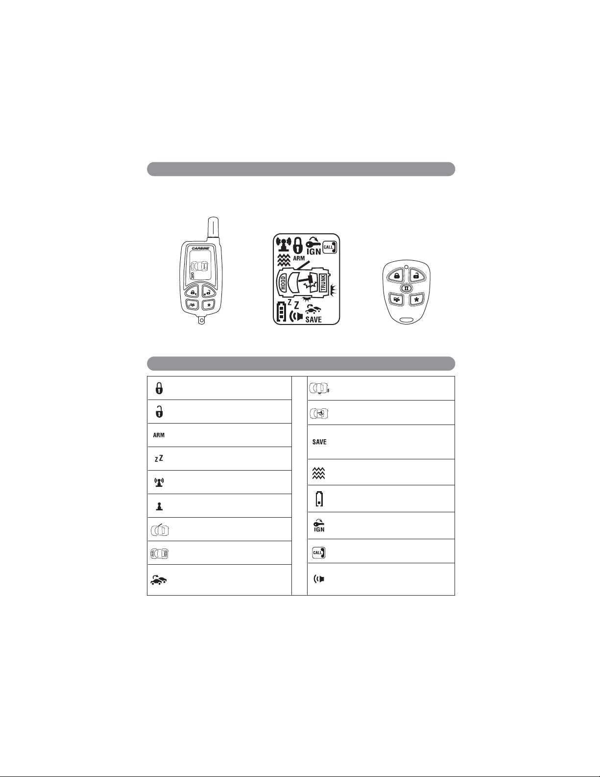
2-Way LCD Remote
LCD Display Icons
1-Way Remote
The LCD screen on the 2-way remote control displays graphic icons. It provides visual information
on any trigger of the sensors and around the clock surveillance of your vehicle, as well as
displaying the present status of the system.
SAVE
4
4
Door Lock
Vehicles Doors are Locked
Door Unlock
Vehicles Doors are Unlocked
Armed Mode
Security System is Armed
Valet Mode
Security System is in Valet Mode
Remote Transmission
Transmitting a Signal
In-Range Indicator
You are within Remote Control Range
Door Triggered
Doors are Opened (Zone 3)
Trunk/Hood Triggered
Trunk/Hood are Open (Zone 2)
Second Vehicle
Communicate with a Second Vehicle’s
Security System
Warn Away
Shock Sensor Triggered (Zone 1)
Shock Sensor
Shock Sensor Triggered (Zone 4)
Power Save Mode
Saves The Battery Power when
Transmitter is not in Use
Vibrate Mode
Vibrates when Security System is Triggered
Low Battery
Replace the Transmitter Battery
Ignition
Trigger On Ignition Switch (Zone 5)
Driver Paging / Lost and Found
Someone is Paging you from the Vehicle
System Trigger/Panic
Alerts that the System has been
Triggered
Remote Control Transmitters
LCD Remote Icons
3
Page 4
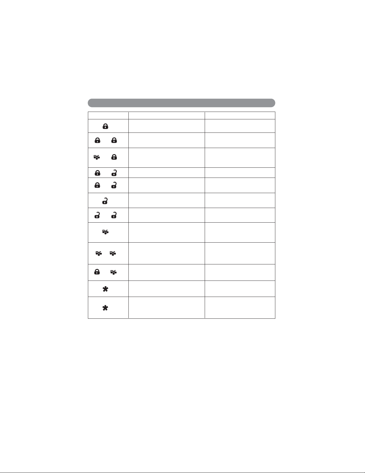
Transmitter Button
System Function Remark
Lock Doors and Arms System
Arm and Delete the 2-Stage
Shock Sensor
Arm System and
Hidden Alarm Function
Silent Arming/Disarming
Active Anti-Car Jacking Mode
Unlock Doors and Disarm System
Two Step Door Unlock and
Disarm System
Trunk Release - Channel 3
Passive Arming Bypass
Channel 4 Timer Control Output
Car Locator
Panic Function
Press Twice within 3 Seconds
Press Each within 3 Seconds.
Ignition in “Off” Position
Ignition in “On” Position,
Press and Hold for 2 Seconds
Press Twice within 3 Seconds
Press and Hold for 1.5 Seconds.
While the System is “Disarmed”.
Press Both and Release
Press and Release
Press and Hold for 3 Seconds.
-
+
-
+
-
-
+
Quick Reference Remote Transmitter Operation (2way and 1way Remotes)
4
Page 5
Vibration/Melody Mode
This mode is useful when you are in a noisy place and it is difficult to hear the beep from the
transmitter. While in the “Vibration/Melody” mode, the transmitter will vibrate if your security
system has been activated.
1. Press and hold the and buttons at the same time until one long beep is
heard. Programming has now been entered.
2. Within 5 seconds, press the button to select the “Vibration” or “Melody”
mode. The icon will be displayed on the screen to show the remote
transmitter is in “Vibration” mode.
3. To exit the programming mode, take no action for five seconds. The remote
control will generate two long beeps to indicate programming mode has been
exited.
Power Save Mode
While in the “Power Save” mode, the LCD remote transmitter will “Sleep” until a
button is pushed, extending the life of battery. When power save mode is “Off”,
the remote control will wake up periodically to check for messages from the
security system.
1. Press and hold the and buttons at the same time until one long beep is
heard. Programming has now been entered.
2. Within 5 seconds, press the button to toggle between “On” or “Off”. The
remote will beep once for “On”, and twice for “Off”. When “Power Save” mode is “On”, the
icon on the LCD screen indicates entry into “Power Save” mode.
3. To exit programming mode, take no action for five seconds. The remote control will generate
two long beeps indicating programming mode has been exited.
Screen Lamp On
Press the button once, and the LCD screen lamp will turn on for 5 seconds.
System Status Check
To check the system’s present status through the LCD screen, press the
transmitter button first, then within 3 seconds press and buttons at the
same time. The response will be one melody sound, and the LCD screen will be
illuminated. Note: If no response is received, then you are out of range.
Clear the Flash Icon and Melody Sound
Press the button first, then within 3 seconds press the and buttons at the same time.
These steps will clear the flash icon and melody sound on the LCD transmitter.
Stop the Trigger Melody Sound
When the alarm is triggered the LCD screen will alert the user through a melody sound and a
flashing trigger icon. Press any button on the LCD transmitter to stop melody sound only, and the
remote control will not send a command to the system.
LCD Transmitter Setup and Operation
5
Page 6

Press Buttons at the Same Time: Then Press Button Within: System Function
5 Sec.
Switching to 2nd Vehicle
or Returning to 1st
Vehicle Operation
5 Sec.
Melody / Vibration Mode
5 Sec.
Power Save Mode
LCD Screen Lamp
Turns On for Five Seconds
3 Sec.
System Status Check
3 Sec.
Clear the Flash Icon
and Melody Sound
+
+
+
+
The LCD remote control is powered by a 1.5 Volt
AAA Alkaline battery. When the power of the
battery weakens the battery icon will be
displayed on the screen. When the old battery is
replaced with a new one, there will be a beep to
indicate the power is up. To replace the battery,
follow the steps in the illustration at left.
Note: Press the button two times when the
battery compartment is empty, then insert the
new battery.
The transmission range may decrease if the system encounters interference from tall structures or
stronger radio frequencies such as high-voltage power lines.
LED Function
Off System is Disarmed
Slow Flashing System is Armed
Fast Flashing System in Automatic Arming
On Solid System in Valet Mode
2 Flashes - Pause Zone 2, Trigger on Trunk/Hook
3 Flashes - Pause Zone 3, Trigger on Door Switch
4 Flashes - Pause Zone 4, Trigger on Shock Sensor
5 Flashes - Pause Zone 5, Trigger on Ignition Switch
+
6
LCD Transmitter Setup and Operation
(continued)
Alarm Indicators
Interference
Battery Replacement
LED Indicators
Page 7

Siren/Horn Chirp Indicators
Chirp Function
1 Chirp System is Armed
2 Chirps System is Disarmed
3 Chirps Ajar Warning
4 Chirps Disarm / Triggered
6 Chirps Car Locator
Parking Light Flash Indicators
System Characteristics
Flash Function
1 Flash System is Armed
2 Flashes System is Disarmed
3 Flashes Disarmed / Triggered
12 Flashes Car Locator
Siren/Horn
Parking
Light
LED Doors Starter Dome Light
1. Arming 1 or 3 Chirps 1 Flash Slow Flash Locking
Disabled
(Option)
2. Disarming 2 or 4 Chirps
2 or 3
Flashes
Unlocking
Turns on for
30 Seconds
3. Trigger Alarming Flashes Slow Flash
Disabled
(Option)
Flashes
4. Panic Alarming Flashes Flashes
5.Car
Jacking
Alarming Flashes
Disabled
(Option)
Flashes
6.Car
Locator
6 Chirps 12 Flashes Locking
7
Alarm Indicators
(continued)
Page 8

1. Press the button on the transmitter.
2. The siren will chirp once and parking lights will flash once indicating that the system is now
armed. The vehicle’s doors will lock upon arming.
Ajar Warning:
If the siren sounds 3 chirps,
then you have left a door,
trunk, or hood lid ajar.
Silent Arming/Disarming
Press the transmitter and buttons at the same time to arm or disarm your security system.
No chirp sound will be heard. The arm/disarm confirmation will be through the vehicle’s parking
lights only.
Shock Sensor Bypass
Press the button on the transmitter two times within 3 seconds. This will arm the security
system and bypass the shock sensor. The system will chirp one additional time to confirm the
Sensor Bypass Mode was activated. The sensor bypass feature is programmed to activate for
one arming cycle only. The security system will return to normal operation during the next
arming cycle.
Hidden Alarm Function
Press the button first, within 3 seconds press the button to activate the hidden alarm
function. The security system will arm, but the siren / horn will be silenced even if the sensor is
triggered in the armed status.
Manual arming/disarming is controlling your security system via the remote transmitter. This
security system is equipped with an optional Automatic Arming feature which allows the security
system to arm 30 seconds after the last door is closed. Operation is as follows:
1. Turn the ignition to the “Off” position and exit the vehicle.
2. After all entrances are closed, the security system LED will flash fast for 30 seconds. If you
reopen any door, hood, trunk the security system LED will stop flashing. It will begin flashing
again once the vehicle’s entrances are closed.
3. After the 30 second timer has elapsed, the security system will automatically “ARM”. The
siren/horn will chirp once, and the parking lights will flash once.
Automatic Arming with Automatic Door Locking (Programmable Option)
The vehicle doors will automatically lock after the passive arming cycle has been completed.
System Armed
8
Security Operation (LCDTX and STD TX)
Manual Arm/Lock
Automatic Arming (Optional)
Door Ajar Trunk/Hood Ajar
Page 9

Automatic Arming Bypass
While the system is in Disarmed Mode, press the button twice. The horn/siren will respond
with one chirp and the LED will turn “On”. The security system will remain in this mode for as
long as you wish. To exit this mode press the or buttons and the system will return to
normal status.
1. Press the button on the transmitter.
2. The siren will chirp twice and parking lights will flash twice indicating that the system is now
disarmed. The vehicle door will unlock and the dome light will turn on for 30 seconds upon
disarming when interfaced with the security system.
Tamper Disarming
If the security system is triggered upon disarm, the siren will chirp 4 times and the parking
lights will flash 3 times.
Pathway Illumination (Optional)
This feature turns the parking lights “On” for 30 seconds upon a unlock signal and for 10
seconds upon the lock signal.
Two-Step Door Unlock (Optional)
This feature will independently unlock the driver’s door only when disarming the security
system. Pushing the button a second time within 3 seconds will unlock the other doors.
Automatic Rearm (Optional)
If this feature is selected, the security system will automatically rearm itself within 60 seconds
after disarming with the remote transmitter. Automatic rearm will cancel if any door is opened
before the 60 second timer has elapsed.
The override function may be used if the remote transmitter is lost or inoperative.
1. Enter the vehicle and turn the ignition switch to “On” position (alarm will sound).
2. Within 10 seconds push and release the valet switch. The alarm will stop sounding and enter
the “Disarm” mode. You can now start and operate the vehicle normally.
9
Security Operation
(continued)
Manual Disarm/Unlock
Emergency Override Operation
System
Disarmed
Doors
Triggered
Trunk/Hood
Triggered
Shock Sensor
Triggered
Ignition
Triggered
Page 10

The valet mode allows you to temporarily bypass all alarm functions eliminating the need to hand
your transmitter to parking attendants or garage mechanics. When the system is in “Valet” mode,
all alarm functions and remote start functions are bypassed. However, the remote panic feature
and remote door locks remain operational. To use the “Valet” mode, the system must first be
disarmed either by using your remote transmitter, or by operating the manual override sequence.
The transmitter can be used as a remote panic switch to manually trigger the alarm system in
case of an emergency.
1. Press and hold the button for 3 seconds to enter the “Panic” mode, and horn will start to
sound.
2. While in “Panic” mode the transmitter and buttons can be used to lock and unlock the
door (if that option is installed). However, if the button is pressed, the vehicle’s starter
disable device (when installed) will be disabled, allowing the vehicle to start.
3. To turn off the panic function, press and hold the or or button for 3 seconds or press
the button once.
4. If the panic function is not turned off by the transmitter, it will turn off and reset itself after 30
seconds.
10
Valet Mode Operation
Security Operation
(continued)
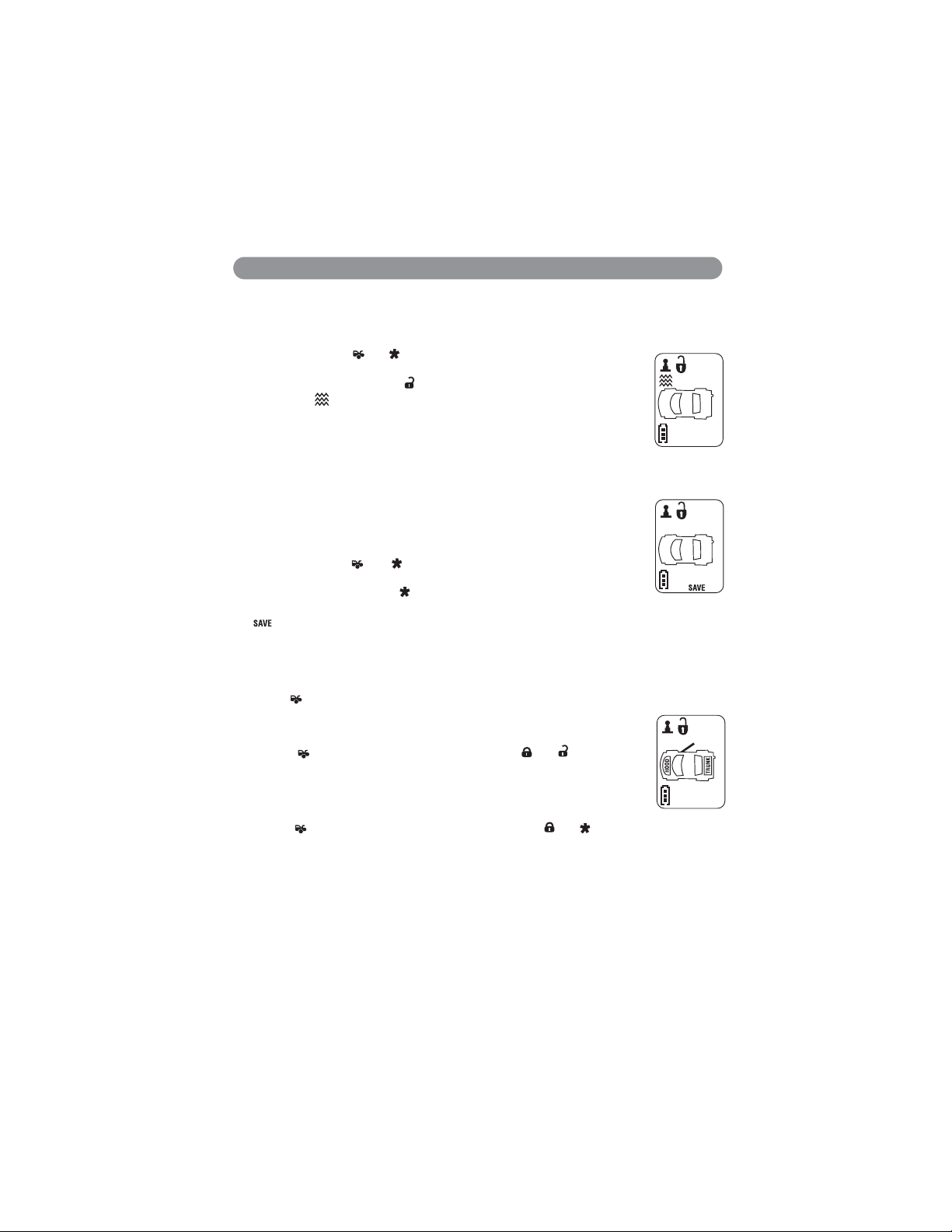
Progressive Remote Vehicle Locator System
Remote Panic Alarm Operation
1. While in disarmed mode, turn the ignition to “Off”
position and open the drivers door.
2. Push and hold the and buttons until the door
locks cycle “Lock/Unlock”. The LED will will flash every
5 seconds while the unit is in the valet mode.
1. While in disarmed mode, turn the ignition to “Off” position and open the drivers door.
2. Push and hold the and buttons until the door locks cycle “Lock/Unlock”.
The LED will will be off indicating the alarm is out of the valet mode.
Enter the Valet Mode:
Exit the Valet Mode:
Note: The remote vehicle location system is active 30 seconds after the alarm is armed.
1. Press the button to active the vehicle locator system. The horn/siren will beep 2 times and
the parking lights will flash 3 times. This operation will repeat a second time.
2. Press the button again within 30 seconds. The horn/siren will beep 3 times and the parking
lights will flash 3 times. This operation will repeat a second time.
3. Press the button again within 30 seconds. The horn/siren will beep 6 times and the parking
lights will flash 6 times.
Remote Door
Lock
Remote Door
Unlock
Page 11

Warning: This security system has a car jacking feature. Its default setting is “Off”. So be sure to
enable this feature if you feel it is needed.
Active Anti-Car Jacking
1. Press and hold the transmitter and buttons at the same time for 2 seconds while the
vehicle’s ignition is “On”. The parking lights will turn on for 1.5 seconds to indicate the
system has entered the “Anti-Car Jacking” mode.
2. Once the system is armed in the “Anti-Car Jacking” mode, the system will trigger when the
door is opened and closed while the ignition is “On”.
Passive Anti-Car Jacking
1. Turn the ignition switch to the “On” position, and the system will enter the “Anti-Car Jacking”
mode.
2. Once the system is armed in the “Anti-Car Jacking” mode, the system will trigger when the
door is opened and closed while the ignition is “On”.
Trigger the Anti-Car Jacking Mode
A. 50 seconds after the system has been triggered. The siren will start chirping for 15 seconds.
B. During this 15 second period of chirping, you can push the valet switch once to turn off the
car jacking feature.
C. 65 seconds after the system has been triggered. The siren starts sounding and the parking
lights start flashing.
D. 90 seconds after the system has been triggered:
1. The siren will still be sounding and the parking lights flashing.
2. The starter disable will activate to prevent the vehicle from starting.
3. “Anti-Car Jacking” mode will remain active until the override procedure is performed or the
vehicle's battery power is exhausted.
Override the System to Turn Off Anti-Car Jacking
Turn the ignition switch from “Off” to “On”, and within 10 seconds push the valet switch. The
siren will stop sounding and the security system is now disarmed.
11
Security Operation
(continued)
Anti-Car Jacking Operation (Optional)
Page 12

Based on the programming done at the time of installation, this function can operate in (5)
different ways. Press and hold the and button at the same time to activate the channel 4
output.
1. Channel 4 output will pulse 1 time for 1 second.
2. Channel 4 output will latch on. Turning on the ignition key will turn it off.
3. Channel 4 will have output as long as you are holding down the and buttons.
4. Channel 4 will have output for 15 seconds then turn off.
5. Channel 4 will have output for 30 seconds and turn off.
The security system has a unique feature for using your vehicle’s dome light:
1. Upon disarming the vehicles security system, the interior dome light will remain on for 30
seconds.
2. If the security system is triggered, the dome light will flash for the same duration as the
horn/siren.
Note: Turn “On” the ignition switch or arm the system to turn off the dome light.
If the vehicles door locks have been interfaced with the security system, the system will
automatically lock the doors when the ignition is turned “On”, or unlock the doors when ignition
key is turned “Off”.
Press and hold the button for two seconds to activate the trunk release (channel 3 output)
and/or any other devices connected.
If the “Out-of-Range Indication” feature is activated the system will automatically check the range
every 30 minutes after being armed.
1. If the user is within the range, the icon will appear on the LCD screen.
2. If user is out-of-range, the icon will disappear from the LCD screen and the transmitter will
beeps 5 times.
Note: Activating this feature will decrease the life expectancy of the battery.
Driver Paging / Lost and Found is useful the event that someone wants to page
the driver of the parked vehicle, or someone cannot find the LCD transmitter.
With the ignition switch in the “Off” position, press and hold the valet switch for
2 seconds to page the driver. One chirp shall be emitted and the paging melody
continues sounding from the LCD transmitter and will flash on the screen.
12
Security Operation
(continued)
Out-of-Range Indication (Optional, LCD Remote Only)
Driver Paging / Lost and Found (LCD Transmitter Only)
Timer Control Output (Channel 4) (Optional)
Trunk Release Output (Channel 3) (Optional)
Ignition Controlled Door Locks (Optional)
Dome Light Supervision (Optional)
Page 13

If your transmitters have been programmed to a second Marksman security system, follow the
steps below:
For LCD Remote Control Transmitter
Second Vehicle Operation:
1. Press and hold and buttons at the same time until one long beep is
heard. Programming Mode has now been entered.
Note: No action for five seconds will generate two long beeps indicating the
Programming Mode has been exited.
2. Within 5 seconds, press and hold the button until two beeps are heard and
the icon is displayed on the LCD screen. The transmitter is now in 2nd car
operation mode.
3. With the is displayed, press any button on the transmitter to control the second vehicle’s
security system, alarm function or remote short function.
Note: Button functions are the same for the second vehicle as they are for the first vehicle.
Return to First Car Operation
1. Press and hold and buttons at the same time until one long beep is heard.
Programming Mode has now been entered.
Note: No action for five seconds will generate two long beeps indicating the
Programming Mode has been exited.
2. Within 5 seconds, press and hold the button until one beep is heard and the
icon is not displayed on the LCD screen indicating first vehicle operation.
For 1-Way Remote Transmitter
Press the II button on the 1-way transmitter, the LED will light up for approximately 2 seconds.
During that time, any single command can be sent to a second vehicle security system.
13
How to Control a Second Marksman Security System
II- Arm / Lock
II- Disarm / Unlock
II- Trunk Release
II- Car Finder
Page 14

1-Way Remote for
X4 - X7 Security System X7RF $59.95 ea.
Replacement Parts and Accessories
SAVE
4
4
2-Way LCD Remote for
X4 Security System X4-RFLCD1 $139.95 ea.
TRANSMITTERS DESCRIPTION MODEL # $ PRICE
BATTERIES
1.5 Volt AAA Alkaline Battery
CR2032 - 3 Volt Lithium Battery (1 pc.)
Models:
Radio Shack: #23-162
Duracell: #DL2032
Eveready: #ECR2032
Panasonic: # CR2032
CR2032
14
Page 15

Credit Card or Money Order Only
Parts and Accessories Order Form
15
(Sorry No Cash, C.O.D. or personal checks accepted)
Call: (310) 884-7777 Fax: (310) 637-9542
SHIP TO: (No P.O. Boxes)
LAST NAME FIRST NAME INITIAL
STREET ADDRESS
ADDITIONAL ADDRESS
Mail to: Magnadyne Corporation
ATTN: Consumer Parts Sales
P.O. Box 5365
Carson, CA 90749-5365
ADDITIONAL ADDRESS
CITY STATE ZIP CODE
DAY TIME PHONE NUMBER
CREDIT CARD INFORMATION
CREDIT CARD N0.
CARD HOLDER’S LAST NAME FIRST NAME INITIAL
STREET ADDRESS
CITY STATE ZIP CODE
PAR
T # DESCRIPTION
Shipping and Handling
Up to $20.00 $5.00
20.01 to 30.00 5.95
30.01 to 45.00 6.50
45.01 to 70.00 6.95
Over 70.01 7.95
Please give a shipping address where this order may be delivered between the hours of 9 am and 5 pm weekdays.
If UPS is unable to deliver, your order will be returned and additional shipping charges will be required.
On regular orders please allow 4-5 weeks for delivery.
California Residents Add Sales Tax = ________ . ______
Shipping and Handling (See Chart) = ________ . ______
EXPIRATION DATE
QTY. PRICE EACH TOTAL
Sales Subtotal = ________ . ______
TOTAL = ________ . ______
VISA
MC
Page 16

Limited Lifetime Warranty
Magnadyne Corporation or its authorized agents will, for the life of the vehicle and to the original
purchaser, repair, replace or refund the retail sales price of said product or any part thereof, at the
option of the Magnadyne Corporation or its authorized agents, if said product or part is found
defective in materials or workmanship, when properly connected and operating on the correct
power requirements designated for the specific product. This warranty and Magnadyne Corporation
or its authorized agents obligations, hereunder do not apply where the product was: damaged while
in the possession of the consumer, subjected to unreasonable or unintended use, not reasonably
maintained, utilized in commercial or industrial operation, or serviced by anyone other than
Magnadyne Corporation or its authorized agent, or where the warning seal on the product is broken
or the power plugs or wires are detached from the unit. Magnadyne Corporation or any of its
authorized agents do not assume any labor costs for the removal and reinstallation of any product
found to be defective, or the cost of transportation to Magnadyne Corporation or its authorized
agents. Such costs are the sole responsibility of the purchaser.
This warranty does not cover the cabinet, appearance items, normal wear and tear or accessories
used in connection with the product resulting from improper installation, alteration, accident,
misuse, abuse or acts of nature.
This Limited Life Time Warranty applies only to the receiver section of the security system. Neither
the siren, transmitters, wire harness or any accessory item added to or used with a Remote Mobile
security system are covered by this Limited Life Time Warranty. Sirens, transmitters, wire harness
or any accessory item are covered by our standard 12 month limited warranty.
Magnadyne Corporation or its authorized agents shall not be liable to anyone for consequential
or incidental damages or claims that may arise due to failure of product to operate properly
except those accorded by law. Magnadyne's or its authorized agents liability to the repair,
replacement of the product as stated above if all conditions of the warranty are met. No
expressed warranty or implied warranty is given except those set forth herein. Magnadyne does
not warrant or guarantee against break in damage or the theft of the vehicle in part or whole, or
against the loss or damage to the contents of any vehicle in which a security system is installed.
Magnadyne security systems are only a deterrent against possible theft.
This warranty extends only to the original purchaser of the product and for the vehicle in which it
was originally installed. This warranty is not transferable or assignable to any person or vehicle.
Defective merchandise should be returned to the original point of purchase or secondly to
Magnadyne Corporation, 1111 W. Victoria Street, Compton, CA 90220. A return authorization must
be obtained before sending, or merchandise may be refused.
X4-UM 3-4-08 Rev. A
© Copyright 2008 Magnadyne Corporation
 Loading...