

Page 1
Installation Manual
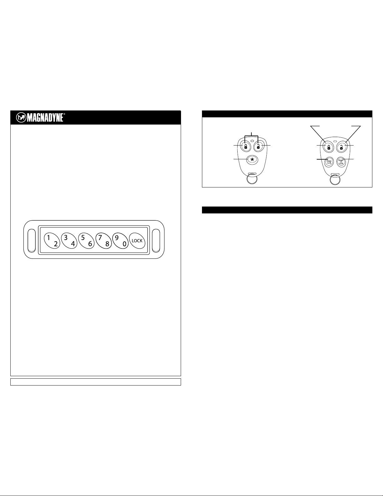
Keypad Keyless
Entry System
Models:
MKE-300A and MKE-400A
For Technical Assistance call (800) 638-3600 or visit www.magnadyne.com
Locks All Doors
(Including Cargo)
Locks All Doors
(Including Cargo)
Press Simultaneously to
Turn On / Off Porch Light
Locks All
Cargo Doors
Unlocks All
Cargo Doors
Unlocks Entry
Doors
Turns On / Off Porch Light
(Can be Programmed to
Unlock Cargo Doors)
Unlocks Entry
Doors
Unlocks Cargo Doors
(Can be Programmed to
Turn On / Off Porch Light)
Transmitters
2
Programming
A. 3-Button Transmitter Programming
Note: This mode will only retain the last 4 remote
transmitters programmed. If the transmitter memory
is exceeded, the security system will start deleting
transmitters from memory in chronological order.
1. Turn the ignition switch to the "ON" position.
2. Within 15 seconds, push the Program Button
(located on the back of the housing) 3 times. The
onboard LED will be flashing and the beeper will
emit a long chirp to indicate the system is in
Transmitter Programming Mode.
3. Press and hold any button on the transmitter
until the onboard LED turns on for 2 seconds and
the beeper responds with a confirming chirp, indicating the signal has been stored into memory.
4. If you have additional transmitters (up to 4)
that need to be programmed, repeat step 3 for
each transmitter.
Exit: Turn the ignition switch to the "OFF" position, or wait for 15 seconds. The onboard LED
turns off and the beeper will emit 3 long chirps to
confirm exit.
B. 4-Button Transmitter Programming
Note: This mode will only retain the last 4 remote
transmitters programmed. If the transmitter memory
is exceeded, the security system will start deleting
transmitters from memory in chronological order.
1. Turn the ignition switch to the "ON" position.
2. Within 15 seconds, push the Program Button
(located on the back of the housing) 5 times, the
onboard LED will be flashing and the beeper will
emit a long chirp to indicate the system is in
Transmitter Programming Mode.
3. Press and hold any button on the transmitter
until the onboard LED turns on for 2 seconds and
the beeper responds with a confirming chirp,
indicating the signal has been stored into memory.
4. If you have additional transmitters (up to 4)
that need to be programmed, repeat step 3 for
each transmitter.
Exit: Turn the ignition switch to the "OFF" position, or leave it for 15 seconds. The onboard LED
turns off and the beeper will emit 3 long chirps to
confirm exit.
C. Feature Programming
1. Turn the ignition switch "ON" then "OFF".
2. Within 15 seconds, push the Program Button
(located on the back of the housing) 7 times, the
onboard LED will be constantly on and the beeper
will emit a long chirp to indicate the system is in
Feature Programming Mode.
3. Press and release the transmitter button or
keypad button that corresponds to the feature
you want to change (see chart). The beeper
chirps and the onboard LED flashing will indicate
setting.
4. Continue to press and release the transmitter
button or keypad button until the beep response
matches your desired setting.
Page 2
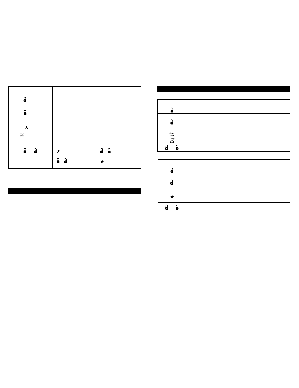
Press Transmitter Button or
Keypad Key
Press the Transmitter Button
or Press and Hold the 1/2 Key
on the Keypad for 3 Seconds
Press the Transmitter Button
or Press and Hold the 3/4 Key
on the Keypad for 3 Seconds
Press the Button on the 3Button Transmitter or Press the
Button on the 4-Button
Transmitter or Press and Hold
the 5/6 Key on the Keypad for 3
Seconds
Press the and Button at
the Same time (3-Button
Transmitter Only) or Press and
Hold the 7/8 Key for 3 Seconds
Exit: Turn the ignition switch to the "ON" position, or press the "LOCK" button on the keypad or leave it for 15
seconds. The beeper will emit 3 long chirps and the onboard LED will turn off to confirm exit.
One Beep / One LED Flash
(Factory Default Setting)
Channel 3 Output = Momentary
Output
Channel 4 Output = Momentary
Output
Channel 5 Output = Momentary
Output
Button = Unlock Cargo
Door(s) Control
+ = Porch Light On/Off
Control
Two Beeps / Two LED Flashes
Channel 3 Output = Latched
Output
Channel 4 Output = Latched
Output
Channel 5 Output = Latched
Output
+ = Unlock Cargo
Door(s) Control
Button = Porch Light On/Off
Control
3
Programming
D. Reprogramming All Codes Back to Default
1. Enter the Code "7352000" on the keypad. The
beeper will emit 1 long chirp to confirm the correct
code was entered.
2. Press and hold the "LOCK" key on the keypad
for 5 seconds and until 5 beeps are heard, then
release.
3. The system will reprogram all codes back to
the default setting. The default program code is
"12345" and the default user code is "54321".
E. Changing the Program Code
(The default program code is "12345")
1. Ente r the program code on the keypad. The
beeper will emit a long chirp to confirm the
correct code was entered.
2. Press and hold the "LOCK" key on the keypad
for 2 seconds and until 5 beeps are heard, then
release.
3. Enter a new 4 to 6 digit program code on the
keypad.
4. Finish by pressi ng the "LOCK " key on the
keypad. 1 long beep with 2 short beeps will
confirm the new program code has been stored
into memory.
Exit: If 15 seconds of inactivity occurs during
the above steps, the unit will default back to the
last successfully stored code. 3 longs beeps
confirm exit.
F. Programming the User Code
(The default user code is "54321")
Note: This mode will only retain the last 4 user
codes programmed. If the user code memory is
exceeded, the security system will start deleting
user codes from memory in chronological order.
1. Enter the program co de on the keypad
("12345" is default). The beeper will emit a long
chirp to confirm the correct code was entered.
2. Enter a new 4 to 6 digit user code on the
keypad. Do not use "1234".
3. Finish by pressing the "LOCK " key on the
keypad. 1 long beep with 2 short beeps will
confirm the new us er code has been stored
into memory.
4. If you have additional user codes (up to 4) that
need to be programmed, repeat steps 2 - 3 for
each new user code.
Exit: Press and hold the "LOCK" key for 1 second
or if 15 seconds of inactivity occurs during the
above steps, the unit will revert back to the last
successfully stored code. 3 longs beeps confirm
exit. The unit will revert back to the last successfully stored code. 3 longs beeps confirm exit.
Transmitter Button
System Function
Locks the Vehicle's Doors and
Cargo Door
Unlocks the Vehicle's Doors
Locks the Cargo Door(s)
Unlocks the Cargo Door(s)
Turns the Porch Light On or Off
Remark
Parking Lights Flash Once
1. Parking Lights Flash Twice
2. Dome Light Turns On for 30 Seconds
3. Porch Light Turns On for 30 Seconds
Note: If vehicle is operating from the RV
battery only, the parking lights will not flash.
Upon Vehicle's Door Unlock
Operation
A. 4-Button Transmitter Operation
+
+
Transmitter Button
System Function
Locks the Vehicle's Doors and
Cargo Door(s)
Unlocks the Vehicle's Doors
Unlocks the Cargo Door(s)
(Can be re-programmed to Turn the Porch Light On
or off)
Turns the Porch Light On or Off
(Can be re-programmed to Unlock the Cargo Doors)
Remark
Parking Lights Flash Once
1. Parking Lights Flash Twice
2. Dome Light Turns On for 30 Seconds
3. Porch Light Turns On for 30 Seconds
Note: If vehicle is operating from the RV
battery only, the parking lights will not flash.
Upon Vehicle's Door Unlock
Upon Vehicle's Door Unlock
B. 3-Button Transmitter Operation
4
Page 3

System Function
Locks the Vehicle's Doors and
Cargo Door(s)
Unlocks the Vehicle's Doors
Locks or Unlocks the Cargo Door
(Operation is Sequential)
Turns On the Porch Light or Turns Off the
Porch Light (Operation is Sequential)
Activates the Channel 3 Output
Activates the Channel 4 Output
Activates the Channel 5 Output
Turns On or Off the Beep Feature of the
Keypad
Remark
Parking Lights Flash Once
1. Parking Lights Flash T
wice
2. Dome Light Turns On for 30 Seconds
3. Porch Light Turns On for 30 Seconds
Note: If vehicle is operating from the RV
battery only, the parking lights will not flash.
System must be in Unlocked Mode
System must be in Unlocked Mode
The Output is Active as long as the
Button is Held. Release and Repress
within 5 Seconds to Reactivate. After
5 Seconds, Reenter User Code to
Reactivate.
The Output is Active as long as the
Button is Held. Release and Repress
within 5 Seconds to Reactivate. After
5 Seconds, Reenter User Code to
Reactivate.
The Output is Active as Long as the
Button is Held. Release and Repress
within 5 Seconds to Reactivate. After
5 Seconds, Reenter User Code to
Reactivate.
1 Beep = Keypad Chirp is On (Default)
3 Beeps = Keypad Chirp is Off
C. Keypad Operation
Note: Turn the ignition switch to the "ON" position, or "LOCK" the vehicle's doors to turn off the dome light.
Keypad
Press the "LOCK" Key
Key in the User Code
Press and Hold the
"1/2" Key for 3 Seconds
Press and Hold the
"3/4" Key for 3 Seconds
Key in the User Code,
then Press and Hold
the "5/6" Key for 5
Seconds
Key in the User Code ,
then Press and Hold
the "7/8" Key for 5
Seconds
Key in the User Code,
then Press and Hold
the "9/0" Key for 5
Seconds
Key in the User Code,
then Press and Hold
the "LOCK" Key for 3
Seconds
5
Operation
6
Wire Descriptions
Listed in Order of Pin Position:
Blue Wire: Self polarizing cargo door lock output.
Connect this wire to the lock relay for the cargo
door(s) (200ma capacity).
Green/White Wire:
Self polarizing vehicle door unlock output. Connect
this wire to the unlock relay for the vehicle door(s)
(200ma capacity).
Black Wire: Main system ground. Connect to the
vehicle chassis.
Orange Wire: (-) channel #4 output. Output type is
programmable (200ma capacity).
Violet Wire: (-) channel #5 output. Output type is
programmable (200ma capacity).
Yellow Wire: +12 volt input supplied by switching on
the ignition key.
Red Wire: Vehicle battery + input. Connect this wire
to the (+) post of the vehicle battery. This wire will
provide a power source when the vehicle battery is
not shut off.
White Wire: (Fused) Parking light flash relay input.
Connect this wire to a (+) or (-) power source
(Depending on the parking light voltage requirement)
(Fused 15 amp capacity).
White/Black Wire: Porch light relay output. Connect
this wire to the vehicle porch light trigger circuit.
Blue/White Wire: Self-polarizing cargo door unlock
output. Connect this wire to the unlock relay for the
cargo doors (200ma capacity).
Green Wire: Self-polarizing vehicle door lock output.
Connect this wire to the lock relay for the vehicle
door(s) (200ma capacity).
Red/White: RV battery + input. Connect this wire to
the (+) post of the RV (house) battery. This wire will
provide a power source if the vehicle battery is shut
off.
Black/White Wire: (-) channel #3 output. Output
type is programmable (200ma capacity).
White/Black Wire: (Fused) Porch light relay input.
Connect this wire to a (+) or (-) power source
(Depending on the porch light voltage requirement)
(Fused 15 amp capacity).
Brown Wire: (Fused) Interior light relay input.
Connect this wire to a (+) or (-) power source
(Depending on the interior light voltage requirement)
(Fused 15 amp capacity).
Brown: Interior light relay output. Connect this wire
to the vehicle interior light trigger circuit.
White Wire: Parking/running light relay output.
Connect this wire to the vehicle parking/running light
trigger circuit.
Wire Harness Notes:
1. The cargo door lock/unlock outputs are terminated
into a mini 3-pin plug. For vehicles without an existing
door lock control relay system, use relay pack model
# ALA-DL1. This relay pack will plug directly into the
provided connector and operate up to (4) door lock
motors.
2. The vehicle door lock/unlock outputs are terminated
into mini 3-pin plug. For vehicles without an existing
door lock control relay system, use relay pack model
# ALA-DL1. This relay pack will plug directly into the
provided connector and operate up to (4) door lock
motors.
 Loading...