

Page 1
Installation and
Operations Manual
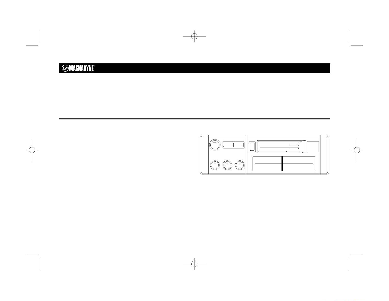
M2080 AM/FM Stereo Receiver and
Auto Stop Cassette Deck
© Copyright 1996
Magnadyne Corporation
M2080 English 08/04/00 7:51 AM Page 1
R
TUNE
POWER AM/FM FF/ EJ
Auto Stop Cassette
VOL BAL TONE
MIN MAX R L HL
STEREO
FM 88 92 96 100 106 108 MHz
AM 5 6 7 10 14 16 x100 KHz
TAPE
Page 2

Congratulations on your purchase of the Magnadyne M2080.
This unit is a precision AM/FM/MPX receiver, and high
fidelity stereo cassette player. This innovative system has
been designed for in-dash installation, and can be installed
in all automotive, motorcycle and marine applications.
Please read all of the information in this booklet before
using this unit to insure that you fully understand the
capabilities of this unit.
ONE (1) YEAR LIMITED WARRANTY
Magnadyne Corporation or its authorized agents will within 1 year from the date of sale to you, repair, replace or refund the retail sales price
of said product or any part thereof, at the option of the Magnadyne Corporation or its authorized agents, if said product or part is found
defective in materials or workmanship, when properly connected and operating on the correct power requirements designated for the
specific product. This warranty and Magnadyne Corporation or its authorized agents obligations hereunder do not apply where the product
was; damaged while in the possession of the consumer, subjected to unreasonable or unintended use, not reasonably maintained, utilized in
commercial or industrial operations, or serviced by anyone other than Magnadyne Corporation or its authorized agents, or where the
warning seal on the product is broken or the power and/or plugs are detached from the unit. Magnadyne Corporation or any of its
authorized agents will not assume any labor costs for the removal and re-installation of any product found to be defective, or the cost of
transportation to Magnadyne Corporation or its authorized agents. Such costs are the sole responsibility of the purchaser.
This warranty does not cover the cabinet appearance items or accessories used in connection with this product, or any damaged to recording
or recording tape, or any damage to the to the products resulting from improper installation, alteration, accident, misuse, abuse or acts of
nature.
MAGNADYNE CORPORATION OR ITS AUTHORIZED AGENTS SHALL NOT BE LIABLE TO ANYONE FOR CONSEQUENTIAL OR
INCIDENTAL DAMAGES OR CLAIMS EXCEPT THOSE ACCORDED BY LAW. NO EXPRESSED WARRANTY OR IMPLIED WARRANTY IS
GIVEN EXCEPT THOSE SET FORTH HEREIN. NO IMPLIED WARRANTY SHALL EXTEND BEYOND 1 YEAR FROM THE DATE OF
SALE.
This warranty extends only to the original purchaser of the product and is not transferable.
Some states do not allow limitations on how long an implied warranty lasts, and some states do not allow the exclusion or limitation of
incidental or consequential damages, so the above limitations or exclusion may not apply to you. This warranty gives you specific legal rights,
and you may have other rights that vary from state to state.
Defective merchandise should be returned to the original point of purchase or secondly, to Magnadyne Corporation, 1111 W. Victoria Street,
Compton CA 90220, or 2061 Cohen Street, Montreal, Quebec H4R 2N7. Return Authorization must be obtained before sending, or
merchandise may be refused.
2
Introduction
M2080 English 08/04/00 7:51 AM Page 2
Page 3
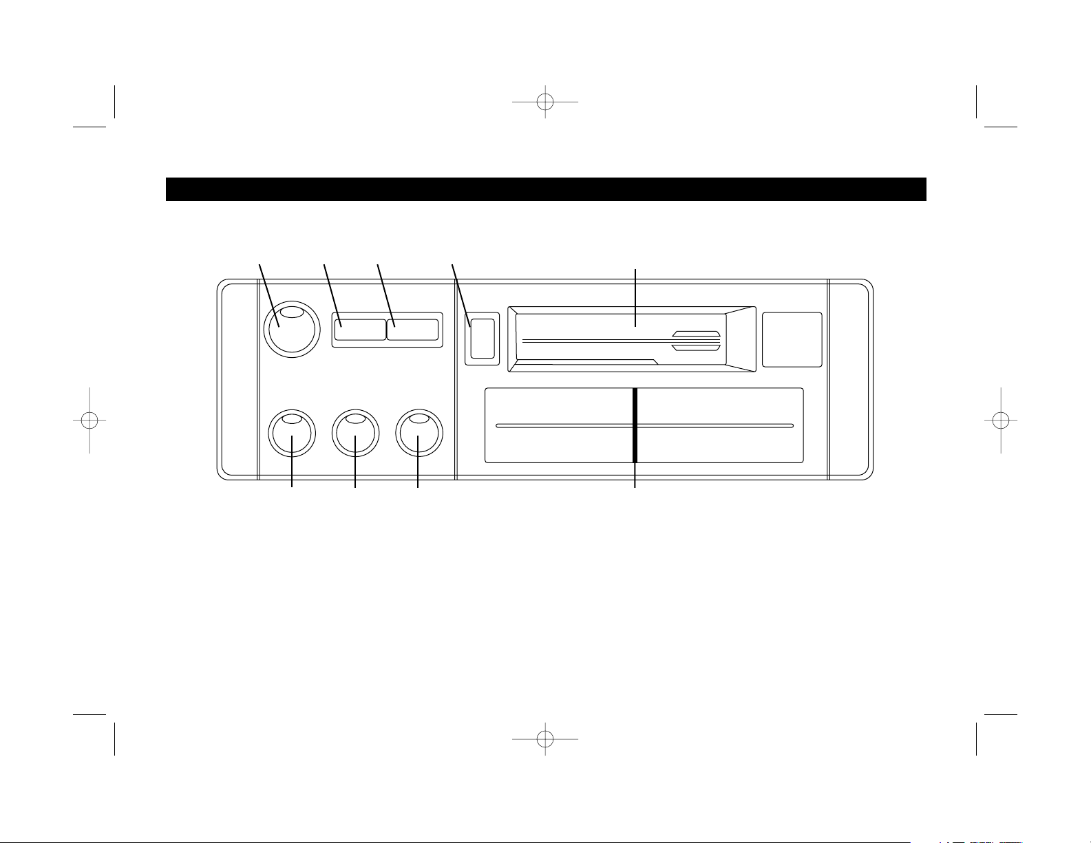
1. Radio Tuning Knob
2. Power On/Off Button
3. AM/FM Band Button
4. Fast Forward/Eject Button
5. Tape Cartridge Door
6. Volume Control Knob
7. Balance Control Knob
8. Tone Control Knob
9. Dial Indicator
TUNE
VOL BAL TONE
POWER AM/FM FF/EJ
STEREO
FM 88 92 96 100 106 108 MHz
AM 5 6 7 10 14 16 x100 KHz
TAPE
MIN MAX R L HL
Auto Stop Cassette
1
87
453
3
2
Controls and Operation
69
M2080 English 08/04/00 7:51 AM Page 3
Page 4

4
1. Radio Tuning Knob
Rotate the radio tuning knob in either direction to select the
desired AM or FM station.
2. Power On/Off Button
Press the Power button to turn the stereo“On” or “Off”.
3. AM/FM Band Button
Press the AM/FM selector button to choose the tuning band you
wish to listen to.
4. Fast Forward / Eject Button
With the tape playing, press this button in halfway until it locks,
to rapidly advance the position of the tape. To release, press the
button lightly and release it. Depressing the button all the way in
will stop the tape from playing and eject the tape from the
mechanism.
5. Tape Indicator Light
A green light will light when the unit is in the tape mode.
6. Volume Control Knob
Rotate this control clockwise. Rotating the control progressively
clockwise will increase the output volume level.
7. Balance Control Knob
Rotate the balance control from left to right to achieve the correct
speaker balance. This control will balance two speakers from left to
right. You will feel a “click” at the center point in the controls
rotation, this is the controls mechanical center.
8. Tone Control Knob
The tone control allows you to vary the overall tone of the music
you are listening to. Rotate the control counter clockwise to
make the tone lower (bass) and clockwise rotation will make the
tone higher (treble).
9. Dial Indicator
This designates the radio station on the dial scale.
Controls and Operation
M2080 English 08/04/00 7:51 AM Page 4
Page 5

5
Radio Operation
1. To turn on the unit, push in the power button.
2. Select either AM or FM radio by using the AM/FM band button.
3. Use the radio tuning knob to select the desired station.
4. Adjust the volume, tone and balance controls to suit your
listening taste.
5. To turn the unit off, simply push the power button.
Tape Operation
1. Insert a cassette into the cassette door with the tape exposed side
facing the right. The cassette will only fit in one way, so if it does
not fit the first try, do not force it! Turn the cassette over and try
inserting it again.
2. Adjust the volume, tone, and balance to your listening taste.
3. To fast advance the tape, press the "FF/EJ" button until it clicks.
Press the button lightly to release it. Press the "FF/EJ" button all
the way in to stop the tape and eject it from the mechanism.
Antenna Trimmer Adjustment
The trimmer is factory adjusted. However, it may require
readjustment depending on the type of antenna which is
employed. If AM reception is poor, adjust the trimmer for
maximum output. Fully extend the antenna, tune to a station
around the 1400kHz spot on the dial. Then insert a flat screwdriver
into the rear of the chassis and carefully adjust the antenna
trimmer for maximum output.
F
M
8
8 92 9
6 1
00
1
06
1
08
MHz
B
A
L
TO
N
E
MIN MAX RLL
1
0
14
1
6
x100 KHz
Controls and Operation
Antenna
Trimmer
M2080 English 08/04/00 7:51 AM Page 5
Page 6

6
Installation
Dashboard
Nut
Washer
Rear Support Strap
Mounting
Sleeve
Sheet
Metal
Screw
Figure 1
M2080 English 08/04/00 7:51 AM Page 6
Page 7

7
Installation
T
U
N
E
V
O
L
T
O
N
E
P
O
W
E
R
A
M
/F
M
E
J
E
C
T
S
T
E
R
E
O
F
M
8
8
9
2
9
6
1
0
0
1
0
6
1
0
8
M
H
z
A
M
5
6
7
1
0
1
4
1
6
x
1
0
0
K
H
z
T
A
P
E
M
I
N
M
A
X
H
L
A
u
t
o
S
t
o
p
C
a
s
s
e
t
t
e
B
A
L
L
R
T
U
N
E
V
O
L
T
O
N
E
P
O
W
E
R
A
M
/F
M
E
J
EC
T
S
T
E
R
E
O
F
M
8
8
9
2
9
6
1
0
0
1
0
6
1
0
8
M
H
z
A
M
5
6
7
1
0
1
4
1
6
x
1
0
0
K
H
z
T
A
P
E
M
I
N
M
A
X
H
L
A
u
t
o
S
t
o
p
C
a
s
s
e
t
t
e
B
A
L
L
R
T
U
N
E
V
O
L
T
O
N
E
P
O
W
E
R
A
M
/F
M
E
JE
C
T
S
T
E
R
E
O
F
M
8
8
9
2
9
6
1
0
0
1
0
6
1
0
8
M
H
z
A
M
5
6
7
1
0
1
4
1
6
x
1
0
0
K
H
z
T
A
P
E
M
I
N
M
A
X
H
L
A
u
t
o
S
t
o
p
C
a
s
s
e
t
t
e
B
A
L
L
R
T
U
N
E
V
O
L
T
O
N
E
P
O
W
E
R
A
M
/F
M
E
J
E
C
T
S
T
E
R
E
O
F
M
8
8
9
2
9
6
1
0
0
1
0
6
1
0
8
M
H
z
A
M
5
6
7
1
0
1
4
1
6
x
1
0
0
K
H
z
T
A
P
E
M
I
N
M
A
X
H
L
A
u
t
o
S
t
o
p
C
a
s
s
e
t
t
e
B
A
L
L
R
T
U
N
E
V
O
L
T
O
N
E
P
O
W
E
R
A
M
/F
M
EJ
E
C
T
S
T
E
R
E
O
F
M
8
8
9
2
9
6
1
0
0
1
0
6
1
0
8
M
H
z
A
M
5
6
7
1
0
1
4
1
6
x
1
0
0
K
H
z
T
A
P
E
M
I
N
M
A
X
H
L
A
u
t
o
S
t
o
p
C
a
s
s
e
t
t
e
BA
L
L
R
T
U
N
E
V
O
L
T
O
N
E
P
O
W
E
R
A
M
/F
M
E
JE
C
T
S
T
E
R
E
O
F
M
8
8
9
2
9
6
1
0
0
1
0
6
1
0
8
M
H
z
A
M
5
6
7
1
0
1
4
1
6
x
1
0
0
K
H
z
T
A
P
E
M
I
N
M
A
X
H
L
A
u
t
o
S
t
o
p
C
a
s
s
e
t
t
e
B
A
L
L
R
1
2
3
4
5
6
Slowly pull the keys out approximately
3/8”. This presses the two stoppers
down and releases the unit.
Slide the unit from the
metal housing.
Slide the keys up
at an angle.
Remove the
end caps.
Insert the keys
on the right and
left side.
Stopper
Release the
rear support
strap
M2080 English 08/04/00 7:52 AM Page 7
Page 8

8
Installation
Space Requirements:
To mount your new Magnadyne unit, you will need a rectangle hole
in the mounting location 183mm (width) x 53mm (height), (7
1
⁄8” x
2
1
⁄8”) and a full 7” of unobstructed space behind the mounting
location.
Step 1:
After obtaining the required space and mounting hold dimensions
required, release the mounting sleeve from the unit by pressing
inward on the sides of the unit and sliding the mounting sleeve off
the unit.
Insert the mounting sleeve into the hole on the dashboard. Secure
it by bending the tabs inward as shown in fig 1. Select the
appropriate tab according to the thickness of the dashboard.
Step 2:
Bring the power, ground, antenna and speaker wires through the
center of the mounting sleeve. Make all the speaker and power
connections to the main harness supplied with the unit. Refer to the
“wiring” section of this unit for proper connection. After all the
connections have been made and are correct, plug the harness and
the antenna cable into the mating plugs located on the rear of the
unit.
Step 3:
Turn on the ignition key and do a pre-installation check of all the
functions with the unit out of the dashboard to make sure that
everything is operating properly before final installation.
Step 4:
Securely attach the rear support strap provided to the rear of the
unit with the fasteners provided. Bend the strap to allow the unit to
slide into it’s mounting sleeve. Reach up behind the unit and grab
the strap while sliding the unit into the mounting sleeve until it
snaps into place. Secure the end of the strap to a solid portion of
the dashboard structure or the fire wall.
Removing the Unit:
In the event that the unit requires removal from it’s mounting
location, repeat the following procedures.
Step 1: Release the rear support strap.
Step 2: Remove the end caps.
Step 3: Insert the keys on the left and right side.
Step 4: Slide the key up at an angle.
Step 5: Slowly pull the key out approximately 3/8” of an inch. This
presses the two stopers down and releases the unit.
Step 6: Slide the unit from the metal housing.
Step 7: Disconnect the wire harness and the antenna.
M2080 English 08/04/00 7:52 AM Page 8
Page 9

9
This unit if for use only with a 12 volt DC power source with a
negative ground.
If your vehicle is equipped with an antenna, connect the lead from
the existing antenna to the antenna receptacle located on the rear
panel of the unit. If not, have an auto antenna installed at an auto
accessories dealer.
Two Speaker System
To obtain the best sound system, make sure that the corresponding
terminals of each speaker pairs are connected
Right Speaker
Left Speaker
Black Wire
Chasis Ground
-
+
-
+
Gray Wire
Green Wire
9-Pin
Plug
From
Radio
Red Wire
Connect to Ignition 12V
3A
Electrical Connections
Two Speaker Wiring
M2080 English 08/04/00 7:52 AM Page 9
Page 10

10
The tape head should be cleaned regularly, especially when the
playback sound begins to deteriorate. Insert a special head cleaning
cassette into the tape mechanism and allow it to run for a few minutes.
If you are playing pre-recorded tape, your tape head should be cleaned
every 10-15 hours of playing time. If you record your own tapes and are
using good quality high bias tape, (chrome or metal type) cleaning
should be performed once a month as high quality tape will not
deteriorate and leave deposits on the tape head as will pour quality
pre-recorded tapes.
Your M2080 will play C-30, C-48, C-60 and C-90 tapes. Avoid playing C120 or larger length tapes. These longer tapes create unwanted loads
on the tape motor and belts causing pre-mature wear. Also, C-120 tape
is thinner and prone to tangle inside the cassette mechanism, no
matter how clean you keep your heads.
Before inserting a cassette into the unit, look through the cassette
window to make sure there is no excess slack, loose turns, and if
necessary, insert a pencil or similar object into the hub reel as shown
below and rotate to take up the slack.
Fuse Replacement
Replace the fuse with only the specified size indicated below.
Fuse for main power wire (Red wire) 3.0 Amp
Cautions and Maintenance
Loose Tape
M2080 English 08/04/00 7:52 AM Page 10
Page 11

11
Tape Section
Play System . . . . . . . . . . . . . 4-Track, 2 Channel Stereo
Tape Speed . . . . . . . . . . . . . 4.75cm/sec. (1 7/8 ips.) +3. -1%
Wow and Flutter . . . . . . . . . 0.3% WRMS Maximum
S/N Ratio . . . . . . . . . . . . . . . More than 40dB
Frequency Response . . . . . 60-10kHz
FM Receiver
Tuning Range . . . . . . . . . . . 88-108mHz
I.F. . . . . . . . . . . . . . . . . . . . . 10.7mHz
Sensitivity . . . . . . . . . . . . . . . 15dB
Image Rejection . . . . . . . . . 50dB / 106mHz
MPX Separation . . . . . . . . . 30dB / 98mHz
MPX Indicator Sensitivity . . . 10uV
AM Receiver
Tuning Range . . . . . . . . . . . 520-1620kHz
Sensitivity . . . . . . . . . . . . . . . 30dB
Image Rejection . . . . . . . . . 58dB Min.
I.F. . . . . . . . . . . . . . . . . . . . . 455kHz
General and Audio Amp
Power Requirement . . . . . . . 11-16D.C. Negative Ground Only
Load Impedance . . . . . . . . . 4-8ohms
Power Output . . . . . . . . . . . . 3.5 Watts RMS/Channel a 4 ohms at 1% THD
7 Watts x 2 Maximum
Frequency Response . . . . . 40Hz-10kHz
Dimensions . . . . . . . . . . . . . 178mm(W) x 152mm(D) x 51mm(H)
Weight . . . . . . . . . . . . . . . . . 1.8Kg (4 lbs.)
© 1996 Copyright Magnadyne Corporation
Specifications
M2080 English 08/04/00 7:52 AM Page 11
Page 12

M2080 English 08/04/00 7:52 AM Page 12
 Loading...