

Page 1
M2 Owner’s & Installation Manual
For technical assistance, please call (800) 638-3600,
or visit www.magnadyne.com
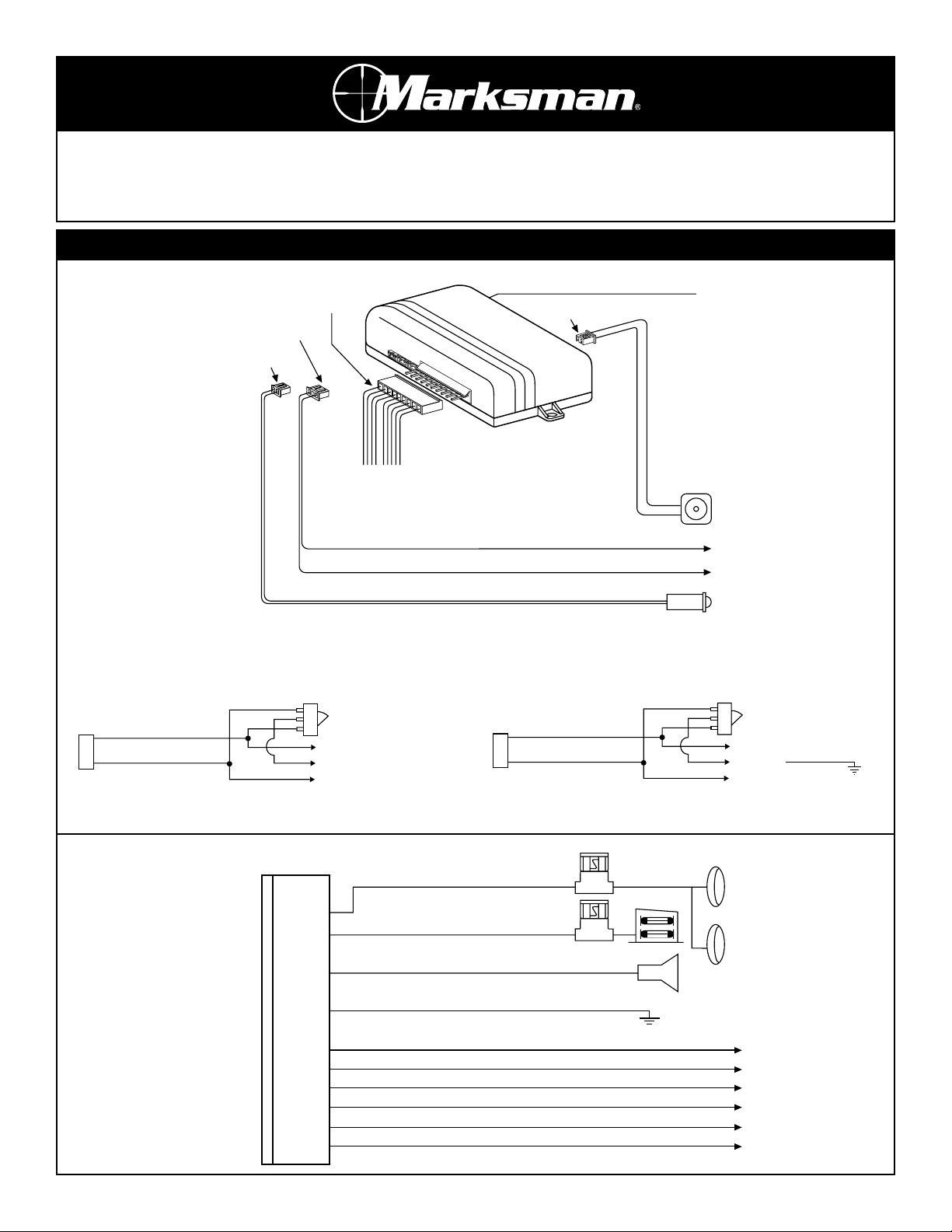
Wiring Diagrams
10-PIN Connection
Black Wire: Antenna (Do Not Ground)
10-Pin White
3-Pin Black
2-Pin White
10-Pin Connector
For Connection Instructions
See Diagram Below
Blue Wire: Door Lock (See Diagram Below)
Green Wire: Door Lock (See Diagram Below)
LED (Optional)
2-Pin Blue
Valet Switch
Positive 3-Wire Door Lock System
Blue Wire
Door Lock
M2
Green Wire
Door Unlock
Negative 3-Wire Door Lock System
Master
Locking
Switch
To Existing Lock Relay
+ 12V
To Existing Unlock Relay
White Wire: Parking Light Output
Red Wire: +12V To Fuse Box (Battery)
Brown Wire: (-) Output To Horn Relay
Black Wire: To Chassis Ground
Orange Wire: 500mA Grounded When Armed (Optional Relay Needed)
Gray Wire: (-) Channel 2 Output (Optional Relay Needed)
Green Wire: (-) Channel 3 Output (Optional Relay Needed)
Blue Wire: Do Not Connect. Please Tape Off
Violet Wire: (-) Dome Light Output (Optional Relay Needed)
Yellow Wire: To Ignition Key (Switched +12V)
Blue Wire
Door Unlock
M2
Green Wire
Door lock
10A
15A
Master
Locking
Switch
To Existing Unlock Relay
Ground
To Existing Lock Relay
Vehicle Parking
Lights
Vehicle Horn
Page 2
A. TRANSMITTERS
A maximum of 4 transmitters can be programmed to function with
this unit. There are two modes of programming. One is Designated
Channel, (Button 1 is door lock/unlock), the other is the Auto
Channel. (Button 1 is door lock, Button 2 is door unlock).
1. Turn Ignition the “On” Position.
Push valet switch 3 times to enter the Designated Channel, or
push valet switch 6 times to enter the Auto Channel. You will
hear one long chirp and one short chirp for the Designated
Channel, or two long chirps and one short chirp for the Auto
Channel.
2. Program Transmitters:
Press any button on first transmitter. One short chirp will confirm that it is programmed. Press any button on second transmitter. Two short chirps will confirm that it is programmed.
Apply the same procedure to program a third and fourth transmitter. Three and four chirps respectively will confirm that the
transmitters are programmed.
3. Exit:
Turn the ignition to the “Off” position, or leave it for 10 seconds. Three long chirps to confirm exit.
Note: If more than 4 transmitters are programmed with this
unit, only the last 4 transmitters programmed will function with
this unit.
B. PROGRAMMING SYSTEMS FEATURES
The M2 has 6 features that are programmable. To program these
features, repeat the following procedures.
1. Turn the ignition key “On” then “Off”. Within 10 seconds, press
the valet switch 6 times. The horn will sound one long beep to
confirm you are in the feature programming mode.
2. Select the feature you want to program by pressing the valet
switch the number of times indicated in the “Feature Number”
of the chart enclosed. The horn will beep the same number of
times you pressed the valet switch to confirm your selection.
Note 1: If the optional LED indicator has been installed, it will
Optional Relay Wiring
Programming
Parking Light (Dual Relay, European Vehicles Only) Starter Disable
Dome Light
Horn Output (Relay is Existing
in Vehicle or Newly Installed)
Channel 3
Channel 2 (Trunk Release)
White Wire
IN4001 Diode
87
87A
85
86
30
IN4001 Diode
87
87A
85
86
30
+12V DC
Left
Orange Wire
OFF ON
Right
ACC
+12V DC
Brown Wire
86
87
87A
30
+
85
Horn
+12V Battery
Gray Wire
IN4001
Diode
87
87A
85
86
30
Start
87
87A
85
86
30
Cut
+12V DC
40A High Current
Relay
Starter
Trunk Release
Switch
Trunk Release
Solenoid
Green Wire
87
87A
86
85
30
+12V DC
+12V or Ground
Depending on
System Requirements
Electric Device
Violet Wire
87
87A
86
30
85
Courtesy Light
+12V DC
Door Switch
Page 3

Feature Number Chirp/LED Confirmation Turn Ignition from “Off” to “On” Turn Ignition from “On” to “Off”
1 Short Chirp Feature “On” 2 Short Chirps Feature “Off”
1 1 Ignition On/Off, Door Lock/unlock No
2 2 Auto Activating Door Locks No
3 3 Doors Locked with Transmitters Doors Locked with Built-in Timer
4 4
After Unlock, Parking Lights Stay On
or 30 sec.
Feature is Off
5 5 Door Lock/Unlock 0.9 Sec. Timer Door Lock/Unlock 3.6 Sec. Timer
6 6 2-Pulse Unlock Off 2-Pulse Unlock On
2-Pulse Unlock Off/On Note:
Set Off: For most vehicles that require only single pulse to unlock the doors.
Set On: For some vehicles that require two pulses to unlock the doors.
Operations
Transmitter Button System Function Remark
Button 1 Lock Door or Unlock Door
Button 1 Panic Function Press for 3 Seconds
Button 2 Pop Trunk Release/Channel 2 Output Press for 2 Seconds
Button 1 & 2 (Both) Silent Door Lock/Unlock
Button 3 Channel 3 Output
Button 4 Car Finder
Transmitter Button System Function Remark
Button 1 Lock Door
Button 1 Panic Function Press for 3 Seconds
Button 2 Unlock Door
Button 1 & 2 (Both) Silent Door Lock/Unlock
Button 3 Pop Trunk Release/Channel 2 Output
Press for 2 Seconds
Button 4 Channel 3 Output
A. TRANSMITTER OPERATION
Designated Channel (4 Button Transmitter)
Auto Channel (4 Button Transmitter)
also flash the same number of times the valet switch was
pressed to confirm the selection.
Note 2: Feature selection is sequential. For example, if you press
the valet switch 3 times to select the passive/active
operation feature, when you are finished programming that
feature you can press the valet switch one more time to select
the “disarm parking lights on” feature to program. Listen for
the beeps and watch the LED indicator (if installed) to confirm
the selection.
3. Once the feature you want to program has been selected,
rotate the ignition key to the position indicated on the enclosed
chart to set the feature. When the feature has been turned
“On”, the horn will beep once. When the feature is turned off,
the horn will beep twice. Refer to the chart enclosed.
Note: In order to program some features, you will have to set
the ignition key to the “On” position and then to the “Off”
position to get the feature programmed correctly.
4. When you are finished setting all the programmable features,
you can do nothing for 15 seconds and the system will exit the
feature programming mode. You can also press one of the
buttons on the transmitter and force exiting the feature
programming mode. The vehicle horn will beep 3 times when
you are out of the feature programming mode.
Button 1 Button 2
Button 3 Button 4
Page 4

C. CHIRP INDICATORS
D. PARKING LIGHTS
E. OVERRIDE/VALET SWITCH
1. Override Function
Use in emergency situations such as a lost transmitter or
transmitter malfunction. Turn ignition “On”, and within 15
seconds push the override/valet switch, the horn will stop and
the system is now disarmed.
F. AUTOMATIC LOCKING
1. Turn ignition “Off”.
2. The LED will fast flash (when this option is installed).
3. After 60 seconds has elapsed, the system will automatically
lock doors.
G. MANUAL LOCKING
1. Press the “Lock” button on the transmitter.
2. The horn will chirp once, after 3 second system arm.
H. MANUAL UNLOCKING
1. Press the “Unlock” button on the transmitter.
2. The horn will chirp twice, indicating system is disarmed.
Note: If ignition is not tuned “On” within 60 seconds after
unlocking, the system will relock again.
I. PANIC FUNCTION
The transmitter can be used as remote panic switch to
manually trigger the horn in case of an emergency. Press and
hold the lock or panic buttons on the transmitter for 3
seconds, and the horn will sound for 30 seconds.
J. IGNITION CONTROL DOOR LOCK SAFETY SYSTEM
Doors will automatically lock after the ignition key is turned
“On”. Doors will automatically unlock after the ignition key is
turned “Off”.
K. TRUNK RELEASE (Channel 2 Pulsed)
Press and hold the trunk release button on the transmitter for
2 seconds to activate the trunk release or other electric devices.
L. CHANNEL 3 (LATCHED)
Press the Channel 3 button to activate the optional electrical
device. This device will be “On” when the button is pressed
continuously, and “Off” when the button is released.
M. VALET MODE
When the door locks are programmed to automatically lock 30
seconds after closing the last door, use the valet mode to
temporarily halt this feature when you give your vehicle to
another person to use or operate. This will prevent the vehicle
from locking 30 seconds after the last door is closed. To operate the valet mode, repeat the following procedure.
1. Turn the ignition key switch to the “On” position.
2. Within 15 seconds, press and hold the valet switch for
approximately 2-3 seconds. Note: If the LED indicator has been
installed, it will light up solid when the unit is in valet mode.
3. To exit the valet mode, repeat steps 1 and 2 again and you will
exit the valet mode.
© Copyright 2003
Magnadyne Corporation
M2-0MIM
Rev. C 4-4-03
Chirp Function
1 Chirp Door Lock
2 Chirps Door Unlock
6 Chirps Car Locator
Parking Light Function
11 Flash Door Lock
12 Flashes Door Unlock
12 Flashes Car Locator
Flash 30 Seconds System Panic
This device complies with part 15 of the FCC rules. Operation is subject to the
following two conditions:
1. This device may not cause harmful interference.
2. This device must accept any interference received, including interference that
may cause undesired operation.
B. LED INDICATORS (when installed)
LED
Function
Off System Off
Slow Flashing Doors Locked
Fast Flashing Lock Timer Countdown
On (Solid) Valet Mode
Operations (continued)
 Loading...