

Magliner GEMINI BULK EDITION User Manual
ASSEMBLY INSTRUCTIONS
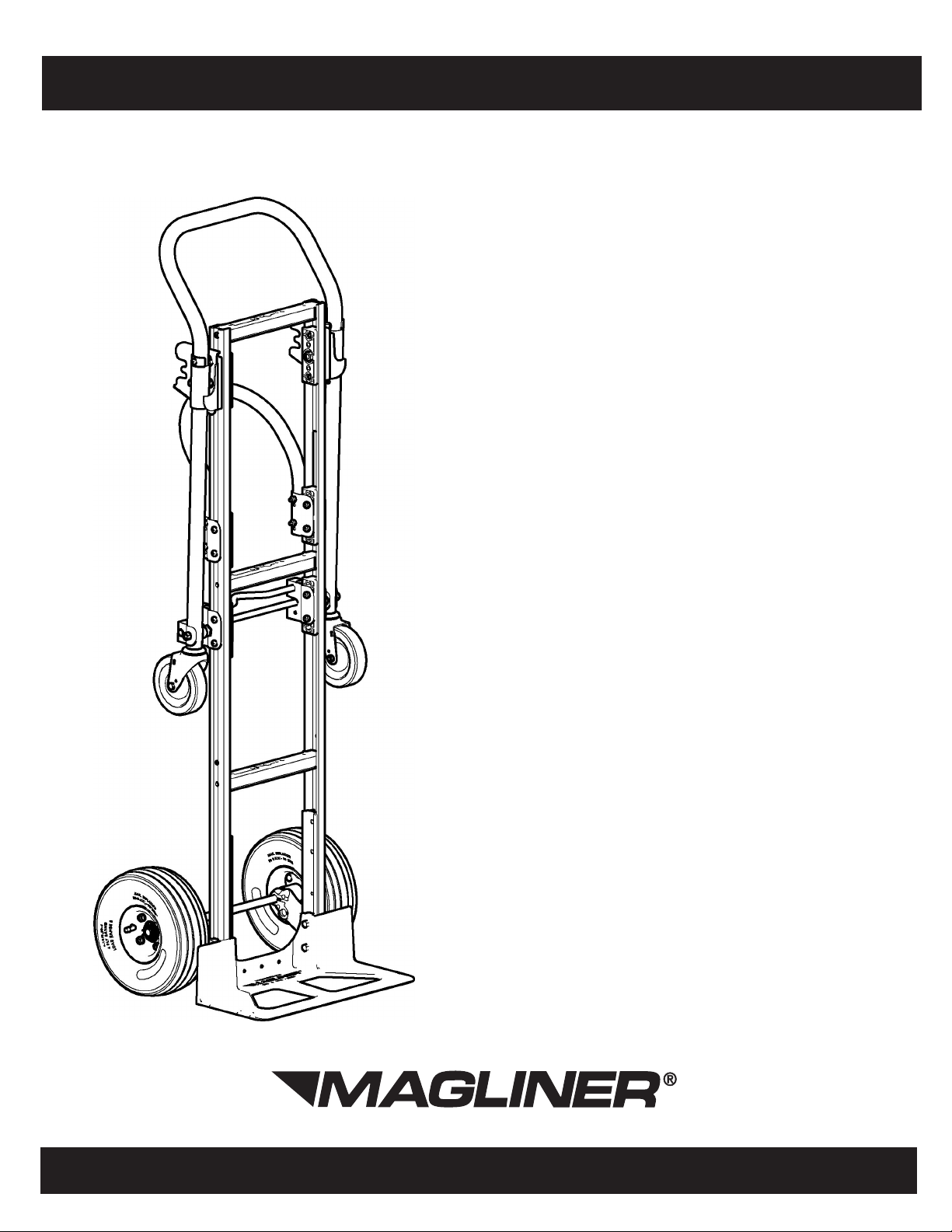
GEMINI
Bulk Container Edition
Table of Contents:
Parts List ..........................................2
Assembly Instructions .................2-4
®
www.magliner.com

TOOLS REQUIRED
• (1) 7/16” WRENCH OR SOCKET
• (2) 1/2” WRENCHES OR
SOCKETS
• (1) 9/16” WRENCH
• (1) 7/8” WRENCH OR SOCKET
• (1) HAMMER
• (1) PLIERS
• (1) #2 PHILLIPS SCREW DRIVER
PARTS LIST
Item Description Qty. Part No.
1 Upper handle assembly 1
2 RH wheel bracket 1 210100
3 LH wheel bracket 1 210101
4 Nose plate 1 Varies
5 18" axle 1 22101
6 Wheel 2 Varies
7 Side channel reinforcement 2 302001
8 Lower handle 1 301000 or 301008
10 Caster assembly 2 Varies
Spreader Rod and Bolt Kit consists of items below:
9 Spreader rod and bracket assembly 1 301058
17 Load bolt 2 301049
18 Spacer for load bolt 2 301061
19 Hex lock nut - 3/8"-16 2 80603
Hardware Pack consists of items below:
12 Hex head screw - 5/16"-18 x 2-1/4" 4 80017
11 Pin coil spring 1/8" x 1-1/8" 2 190104
13 Hex lock nut - 5/16"-18 4 80676
14 5/8" washer thin 4 80707
15 5/8" washer thick 4 80705
16 Cotter pin 2 81077
20
21 Hex lock nut - 1/4"-20 4 80675
Pan head machine screw - 1/4"-20 x
1-3/2" long
301767 (or 301776
handle with hook)
4 80105
The following assembly sequence is recommended:
STEP 1: 1. ASSEMBLING OF THE FRAME, FRAME REINFORCEMENTS, NOSE, WHEEL
BRACKETS, AND AXLE.
Use a workbench or table of convenient height and place all components in view and within reach.
a. Install the two (2) side channel reinforcements into the nose end of the frame making certain holes are aligned (Refer to Figure 2).
b. Slide the legs of the frame down and over the embossments on the heel of the nose casting (Refer to Figure 2).
c. Insert the four 5/16”-18 hex head bolts through the nose, frame reinforcements, and the frame legs. Do Not Secure The Bolts At This Time! (Refer to Figure 2)
d. Install right hand wheel bracket over the protruding bolts. Secure with two 5/16”-18 hex head locknuts. Do Not Tighten The (2) Nuts At This Time! (Refer to Figure
2); (Reference Figure 1 for correct axle hole position).
e. Install one roll pin in the axle and center the pin on the axle, tapping lightly with a hammer (Refer to Figure 4). Repeat for the second roll pin.
f. Insert the axle through the UPPER axle hole. NOTE: Rotate axle until roll pin "locks" into position in the wheel bracket (Refer to Figure 1).
•Note• If Stair Climbers are used, refer to the assembly instructions that were provided with them. If Stair Climbers are not used, continue to Step g.
g. Position and attach the left hand wheel bracket sliding it over the axle to the outside of the frame leg, using two 5/16”-18 hex head locknuts to secure it. Do Not
Tighten The (2) Nuts At This Time! (Refer to Figure 2).
h. Check all components for proper location at this time. Make any adjustments required.
i. Securely tighten nose and wheel bracket bolts.
STEP 2: ASSEMBLING THE WHEELS. (Refer to Figure 4)
a. Slide one thick and one thin wheel washer onto the axle up to the wheel bracket.
b. Slide a wheel on the axle up to the washer (the long hub portion is toward or next to the wheel bracket and washer).
c. Slide the thin wheel washer onto the axle up to the wheel.
d. Insert the cotter pin through the hole at the end of the axle and spread the ends of the cotter pin apart using the pliers.
• Repeat above assembly sequence for the second wheel.
2
 Loading...