

Magliner BRAKE TRUCK Y-Cable User Manual
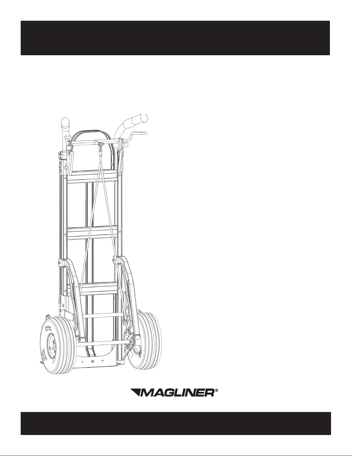
Assembly Instructions
Paddle Brake
Y-Cable
Table of Contents:
Bottom Brake Components ........ 2-3
Brake Handle Components ........ 4-7
Y-Cable Assembly ......................... 7
Brake/Cable Adjustments .............. 8
Warranty Information .................. 8
www.magliner.com
Magline, Inc., 1205 West Cedar Street, Standish, MI 48658 • (800) 624-5463, (989) 512-1000

BOTTOM BRAKE COMPONENTS
PARTS LIST
Item Description Qty. Part No.
A Bottom mounting bracket 2 304152
Hex head cap screw 5/16”-18 x
B
1-1/2” long
2 80013
C Flat washer for 5/16” bolt 2 80701
D Hex locknut 5/16”-18 2 80676
E Pivot shaft 1 304157
F Flat washer for 5/8” bolt - thick 4 80705
G Brake paddle LH 1 304155
H Brake paddle RH 1 304156
I Cotter pin for axle 1/8” x 1” long 2 81077
The above parts are found in 304160, 304161, 304162 and 304163 brake conversion kits.
Tighten all 1/4”-20 screws to 50-60 in.-lbs. and 5/16”-18 screws to 120-140 in.-lbs.
For retrofitting Y-cable brake kit to an existing hand truck see directions at bottom of this page.
TOOLS REQUIRED
(2) 1/2” WRENCHES
(2) 7/16” WRENCHES
(1) #2 PHILLIPS SCREWDRIVER
(1) NEEDLE NOSE PLIERS
(1) RULER OR TAPE MEASURE
ADDITIONAL TOOLS REQUIRED IF
RETROFIT TO EXISTING TRUCK:
(1) ELECTRIC DRILL
(1) 3/8" DRILL BIT
1. The bottom mounting brackets require a hole that lines up with the top hole in the side rail reinforcement
(located on the inside of the bottommost part of all hand truck frames). For hand trucks that already have
holes in the side rails for mounting the bottom mounting brackets, use a screwdriver to punch a hole
through the red stripe.
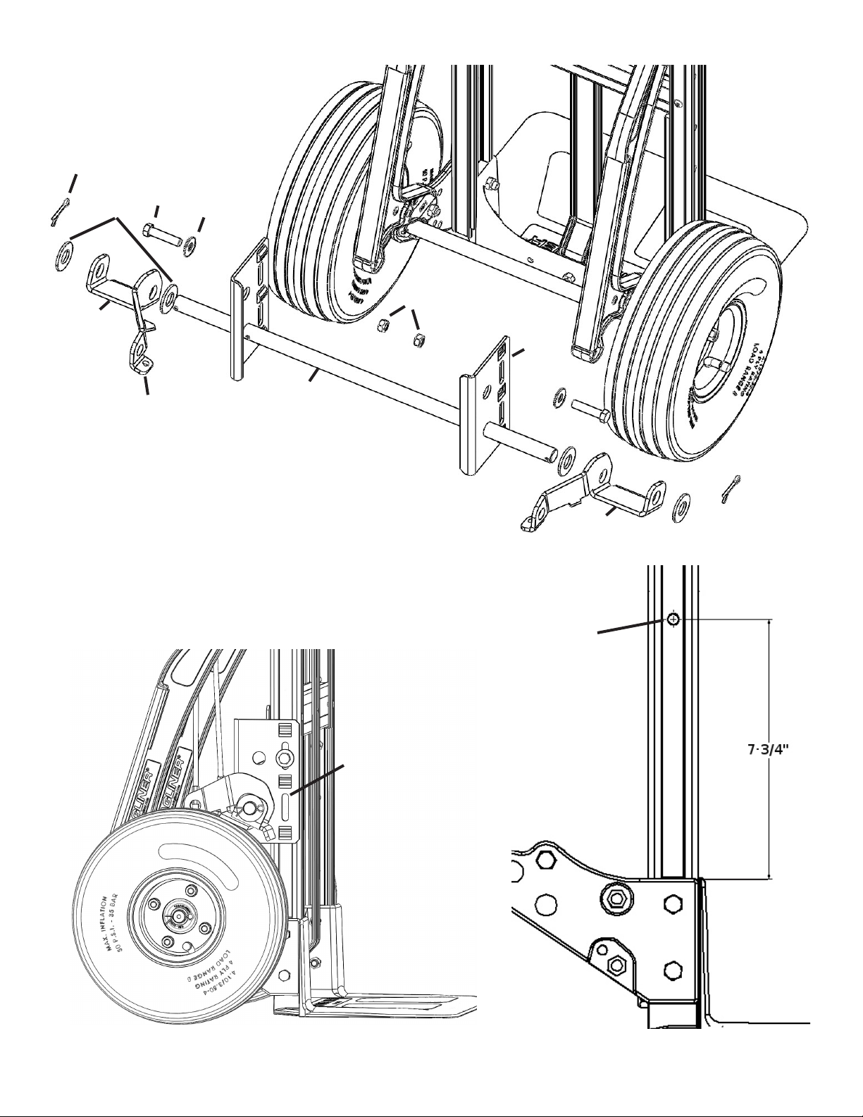
2. Position each of the bottom mounting brackets (A) as illustrated in Figure 2. Fasten with the 5/16” x
1½” long hex head cap screw (B) and one 5/16” washer (C) on the outside through the uppermost slot.
Secure with the 5/16” locknut (D) on the inside. (Note: Do not fully tighten until the final brake adjustment
is done.)
3. Slide the pivot shaft (E) through each of the lower holes provided in the mounting brackets and install a
5/8” washer (F) on each end.
4. Assemble each of the brake paddles (G,H) on the pivot shaft as illustrated, making sure that each of the
extending lower tabs (TAB) are positioned towards the center of the hand truck as shown.
5. Install a second 5/8” washer (F) on each end of the pivot shaft and secure the assembly by inserting a
cotter pin (I) in the holes provided at both ends of the shaft. Bend the ends of each of the cotter pins (I)
using the needle nose pliers to hold it in place.
FIELD RETROFIT
When retrofitting a Y-cable brake kit to an existing hand truck without the side rail hole that lines up with the
top hole in side rail reinforcement, mounting holes will need to be drilled in the frame, one on each side.
1. Using a ruler or tape measure, mark a location in the center of the side rail 7¾” above the wheel bracket
as illustrated in Figure 3 on both sides.
2. Drill a hole using a 3/8” drill bit in the location marked.
2
I
B
F
G
C
D
A
E
TAB
H
Figure 1
A
Drill a 3/8”
diameter hole
if it does not
exist. See FIELD
RETROFIT
instructions.
Figure 2
Figure 3
3
 Loading...