

Page 1
SCOPE
:
⑤ Tolerance Code
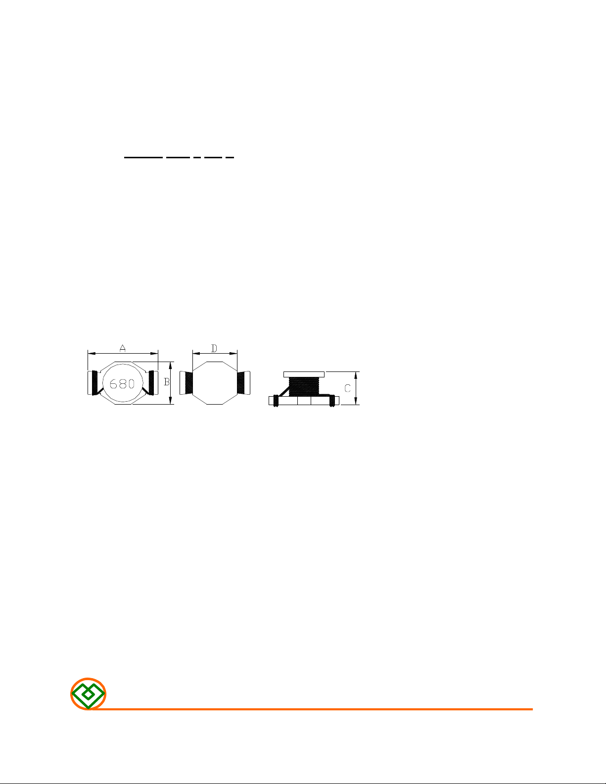
(1) SHAPES AND DIMENSIONS
(2) ELECTRICAL SPECIFICATIONS
(3) CHARACTERISTICS
This specification applies to the Pb Free high current type SMD inductors for
MSCDB-1807H-SERIES
PRODUCT INDENTIFICATION
MSCDB-1807 H-680 M
① ② ③ ④ ⑤
① Product Code
② Dimensions Code
③ High Current
④ Inductance Code
A: 19.40 Max. mm
B: 13.30 Max. mm
C: 6.80 Max. mm
D: 12.2 Typ. mm
SEE TABLE 1
TEST INSTRUMENTS
L : HP 4284A PRECISION LCR METER (or equivalent)
RDC : CHROMA MODEL 16502 MILLIOHMMETER (or equivalent)
(3)-1 Ambient temperature ……......... +60℃ Max.
(3)-2 Operate temperature range ...... -40℃~+125℃
(Including self temp. rise)
(3)-3 Storage temperature range ...... -40℃~+125℃
MAG.LAYERS
MSCDB-1807H-SERIES Page 1/8
Page 2

TABLE 1
MAGLAYERS
PT/NO.
MSCDB-1807H-4R7□
MSCDB-1807H-6R8□
MSCDB-1807H-680□
※ □ specify the inductance tolerance,M(±20%),N(±30%)
※ IDC1: Based on inductance change (△L/Lo: drop 10%Max. )
IDC2: Based on temperature rise (△T: 40℃ TYP.)
Rated DC Current: The less value which is IDC1 or IDC2.
Inductance Percent Test Resistance Rated DC Current
L(μH) Tolerance Frequency RDC(Ω)Max. IDC1(A) IDC2(A)
4.7 N 100kHz,0.25V 12m 6.5 7.0 4R7
6.8 N 100kHz,0.25V 19m 5.8 5.5 6R8
68 M,N 100kHz,0.25V 0.156 1.6 2.0 680
Marking
MAG.LAYERS
MSCDB-1807H-SERIES Page-2/8
Page 3
(4) RELIABILITY TEST METHOD
MECHANICAL
TEST ITEM SPECIFICATION TEST DETAILS
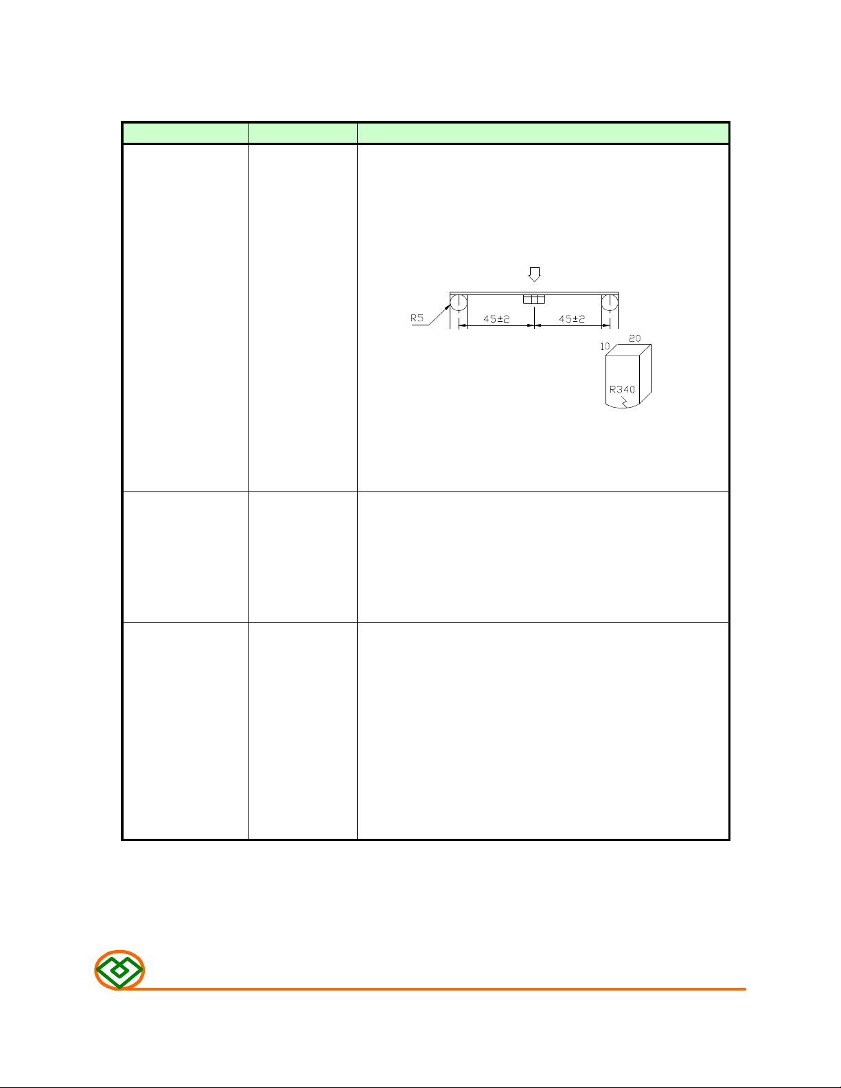
Substrate bending
△L/Lo≦±5%
There shall be direction is made approximately 3mm.(keep time 30 seconds)
no mechanical PCB dimension shall the page 7/9
damage or elec- F(Pressurization)
trical damege.
The sample shall be soldered onto the printed circuit board
in figure 1 and a load applied unitil the figure in the arrow
PRESSURE ROD
figure-1
Vibration
Solderability
△L/Lo≦ ±5%
There shall be and a frequency of from 10 to 55Hz/1 minute repeated should
no mechanical be applied to the 3 directions (X,Y,Z) for 2 hours each.
damage. (A total of 6 hours)
New solder Flux (rosin, isopropyl alcohol{JIS-K-1522}) shall be coated
More than 90% over the whole of the sample before hard, the sample shall
The sample shall be soldered onto the printed circuit board
and when a vibration having an amplitude of 1.52mm
then be preheated for about 2 minutes in a temperature of
130~150℃ and after it has been immersed to a depth 0.5mm
below for 3±0.2 seconds fully in molten solder M705 with
a temperature of 245±2℃.
More than 90% of the electrode sections shall be couered
with new solder smoothly when the sample is taken out of
the solder bath.
MAG.LAYERS
MSCDB-1807H-SERIES
Page-3/8
Page 4

MECHANICAL
Sodering temperature (℃)
(230
℃)
2 min
TEST ITEM SPECIFICATION
Resistance to There shall be Temperature profile of reflow soldering
Soldering heat no damage or
(reflow soldering) problems.
300
250
soldering
(Peak temperature 260±3℃ 10 sec
200
150
100
50
Pre-heating
150 ~ 180℃
30 sec Min
+0
10
sec.
Slow cooling
(Stored at room
temperature)
2 min. or more
The specimen shall be passed through the reflow oven with the
condition shown in the above profile for 1 time.
The specimen shall be stored at standard atmospheric conditions
for 1 hour, after which the measurement shall be made.
ELECTRICAL
TEST ITEM SPECIFICATION TEST DETAILS
Dielectric There shall be AC 100V voltage shall be applied for 1 minute acrosset the top
withstand no other surface and the terminal of this sample
voltage damage or
problems.
Temperature
characteristics
△L/L20℃≦±10%
0~2000 ppm/℃ an ambient temperature of -20 to +85℃,and the value
The test shall be performed after the sample has stabilized in
calculated based on the value applicable in a normal
temperature and narmal humidity shall be △L/L20℃≦±10%.
MAG.LAYERS
MSCDB-1807H-SERIES
Page-4/8
Page 5

ENVIROMENT CHARACTERISTICS
TEST ITEM SPECIFICATION
High temperature
storage
△L/Lo≦ ±5%
There shall be Upon completion of the measurement shall be made after the
no mechanical sample has been left in a normal temperature and normal
damage. humidity for 1 hour.
The sample shall be left for 96±4 hours in an atmospere with
a temperature of 85±2℃ and a normal humidity.
Low temperature
storage
Change of
temperature in the table 2 below and then it shall be subjected to standard
△L/Lo≦ ±5%
There shall be Upon completion of the test, the measurement shall be made
no mechanical after the sample has been left in a normal temperature and
damage. normal humidity for 1 hour.
△L/Lo≦ ±5%
There shall be stmospheric conditions for 1 hour, after which measurement
no other dama- shall be made.
ge of problems
The sample shall be left for 96±4 hours in an atmosphere with
a temperature of -25±3℃.
The sample shall be subject to 5 continuos cycles, such as shown
table 2
Temperature Duration
1
2
3
4
-25±3℃
(Themostat No.1)
Standard 5 sec. or less
atmospheric
85±2℃
(Themostat No.2)
Standard 5 sec. or less
atmospheric
30 min.
No.1→No.2
30 min.
No.2→No.1
Moisuture storage
Test conditions:
The sample shall be reflow soldered onto the printed circuit board in every test.
△L/Lo≦ ±5%
There shall be Upon completion of the test, the measurement shall be made
no mechanical after the sample has been left in a normal temperature and
damage. normal humidity more than 1 hour.
MAG.LAYERS
The sample shall be left for 96±4 hours in a temperature of
40±2℃ and a humidity(RH) of 90~ 95%.
MSCDB-1807H-SERIES
Page-5/8
Page 6

(5) LAND DIMENSION (Ref.)
PCB: GLASS EPOXY t=1.6mm
(5)-1 LAND PATTERN DIMENSIONS
(STANDARD PATTERN)
(5)-2 SUBSTRATE BENDING TEST BENDING TEST BOARD
MAG.LAYERS
MSCDB-1807H-SERIES
Page-6/8
Page 7

(6) PACKAGING
(6)-1 CARRIER TAPE DIMENSIONS (mm)
5.5
(6)-2 TAPING DIMENSIONS (mm)
Unreeling
Direction
MAG.LAYERS
MSCDB-1807H-SERIES
Page-7/8
Page 8

(6)-3 REEL DIMENSIONS (mm)
Tape width
(6)-4 QUANTITY
250pcs/Reel
The products are packaged so that no damage will be sustained.
:32
MAG.LAYERS
MSCDB-1807H-SERIES
Page-8/8
 Loading...