

Page 1
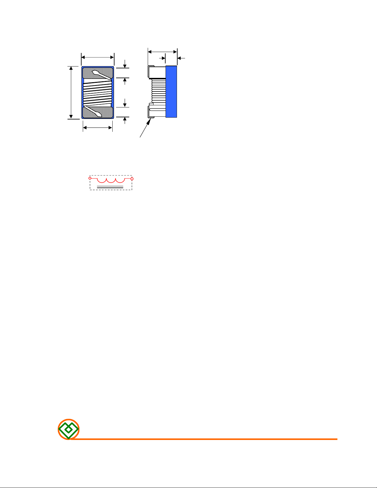
(1) SHAPES AND DIMENSIONS
(2) ELECTRICAL SPECIFICATIONS
(3) CHARACTERISTICS
A
B
E
F
E
G
Terminal
Equivalent circuit
No Polarity
C
D
Terminal wraparound : Approx.
0.18mm both ends
A : 1.65 ± 0.15 mm
B : 1.05 ± 0.15 mm
C : 0.82 ± 0.20 mm
D : 0.45 ± 0.25 mm
E : 0.33 ± 0.10 mm
F : 0.89 ± 0.10 mm
G : 0.90 ± 0.10 mm
SEE TABLE 1
TEST INSTRUMENTS
L,Q : HP 4291B IMPEDANCE ANALYZER (or equivalent)
SRF : ENA E5071B NETWORK ANALYZER (or equivalent)
RDC : CHROMA MODEL 16502 MILLIOHMMETER (or equivalent)
(3)-1 Operate temperature range ...... -40℃~+125℃
(Including self temp. rise)
(3)-2 Storage temperature range ...... -40℃~+125℃
MAG.LAYERS
MHSC-1608C-SERIES
Page 1/8
Page 2
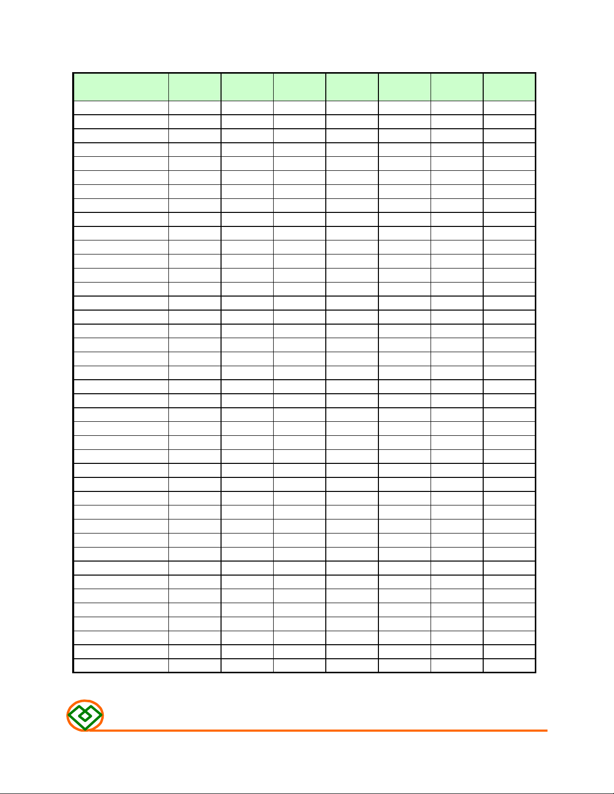
TABLE 1
MAGLAYERS
PT/NO.
MHSC-1608C-1N6□
MHSC-1608C-1N8□
MHSC-1608C-2N0□
MHSC-1608C-2N2□
MHSC-1608C-3N3□
MHSC-1608C-3N6□
MHSC-1608C-3N9□
MHSC-1608C-4N3□
MHSC-1608C-4N7□
MHSC-1608C-5N1□
MHSC-1608C-5N6□
MHSC-1608C-6N3□
MHSC-1608C-6N8□
MHSC-1608C-7N5□
MHSC-1608C-8N2□
MHSC-1608C-8N7□
MHSC-1608C-9N1□
MHSC-1608C-9N5□
MHSC-1608C-10N□
MHSC-1608C-11N□
MHSC-1608C-12N□
MHSC-1608C-13N□
MHSC-1608C-15N□
MHSC-1608C-16N□
MHSC-1608C-18N□
MHSC-1608C-19N□
MHSC-1608C-20N□
MHSC-1608C-22N□
MHSC-1608C-23N□
MHSC-1608C-24N□
MHSC-1608C-25N□
MHSC-1608C-27N□
MHSC-1608C-30N□
MHSC-1608C-33N□
MHSC-1608C-36N□
MHSC-1608C-39N□
MHSC-1608C-43N□
MHSC-1608C-47N□
MHSC-1608C-51N□
MHSC-1608C-56N□
MHSC-1608C-62N□
Inductance Percent Quality L,Q Freq. SRF DCR IDC
L(nH) Tolerance Min. (MHz) (MHz)Min. (Ω) Max. (mA) Max.
1.6 J,K 24 250 12500 0.030 700
1.8 J,K 16 250 12500 0.045 700
2.0 J,K 13 250 12500 0.080 700
2.2 J,K 13 250 12500 0.150 700
3.3 J,K 30 250 5900 0.045 700
3.6 J,K 22 250 5900 0.063 700
3.9 J,K 22 250 6900 0.080 700
4.3 J,K 22 250 5900 0.063 700
4.7 J,K 20 250 5800 0.085 700
5.1 J,K 20 250 5700 0.115 700
5.6 J,K 20 250 5800 0.160 700
6.3 J,K 26 250 5700 0.115 700
6.8 J,K 27 250 5800 0.125 700
7.5 J,K 28 250 4800 0.115 700
8.2 J,K 30 250 4700 0.125 700
8.7 J,K 28 250 4600 0.109 700
9.1 J,K 28 250 4600 0.120 700
9.5 J,K 28 250 5400 0.145 700
10 G,J,K 31 250 4800 0.145 700
11 G,J,K 30 250 4000 0.145 700
12 G,J,K 35 250 4000 0.130 700
13 G,J,K 30 250 4000 0.130 700
15 G,J,K 35 250 4000 0.170 700
16 G,J,K 34 250 3300 0.170 700
18 G,J,K 35 250 3100 0.180 700
19 G,J,K 35 250 3000 0.190 700
20 G,J,K 38 250 3000 0.180 700
22 G,J,K 38 250 3000 0.190 700
23 G,J,K 38 250 2850 0.205 700
24 G,J,K 36 250 2650 0.205 700
25 G,J,K 38 250 2800 0.210 600
27 G,J,K 40 250 2800 0.220 600
30 G,J,K 37 250 2250 0.220 600
33 G,J,K 40 250 2300 0.220 600
36 G,J,K 37 250 2080 0.250 600
39 G,J,K 40 250 2200 0.260 600
43 G,J,K 38 250 2000 0.280 600
47 G,J,K 38 200 2000 0.280 600
51 G,J,K 38 200 2130 0.300 600
56 G,J,K 38 200 1900 0.310 600
62 G,J,K 37 200 1800 0.330 600
MAG.LAYERS
Page-3/9 Page 2/8
MHSC-1608C-SERIES
Page 3
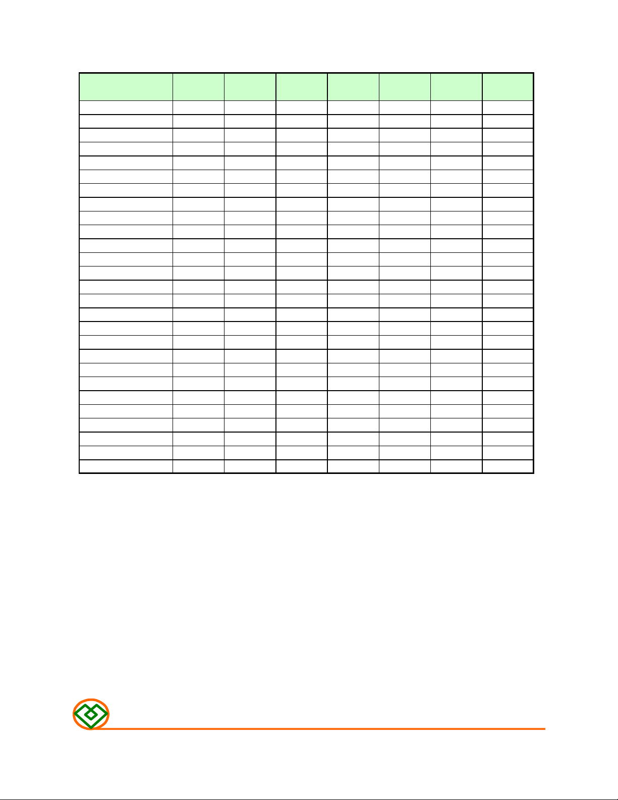
TABLE 1
MAGLAYERS
PT/NO.
MHSC-1608C-68N□ 68 G,J,K 37 200 1700 0.340 600
MHSC-1608C-72N□ 72 G,J,K 34 150 1700 0.490 400
MHSC-1608C-75N□ 75 G,J,K 34 150 1700 0.430 400
MHSC-1608C-79N□ 79 G,J,K 34 150 1700 0.500 400
MHSC-1608C-82N□ 82 G,J,K 34 150 1700 0.540 400
MHSC-1608C-91N□ 91 G,J,K 34 150 1500 0.560 400
MHSC-1608C-R10□ 100 G,J,K 34 150 1400 0.580 400
MHSC-1608C-R11□ 110 G,J,K 32 150 1350 0.610 300
MHSC-1608C-R12□ 120 G,J,K 32 150 1300 0.650 300
MHSC-1608C-R13□ 130 G,J,K 32 150 1200 0.750 280
MHSC-1608C-R15□ 150 G,J,K 28 150 990 0.920 280
MHSC-1608C-R16□ 160 G,J,K 28 150 990 1.050 260
MHSC-1608C-R17□ 170 G,J,K 25 100 990 1.150 240
MHSC-1608C-R18□ 180 G,J,K 25 100 990 1.250 240
MHSC-1608C-R19□ 190 G,J,K 25 100 990 1.350 200
MHSC-1608C-R20□ 200 G,J,K 25 100 990 1.500 200
MHSC-1608C-R22□ 220 G,J,K 25 100 900 1.600 250
MHSC-1608C-R24□ 240 G,J,K 25 100 900 1.900 200
MHSC-1608C-R25□ 250 G,J,K 25 100 900 0.234 250
MHSC-1608C-R27□ 270 G,J,K 24 100 900 2.450 170
MHSC-1608C-R30□ 300 G,J,K 25 100 900 2.700 150
MHSC-1608C-R33□ 330 G,J,K 25 100 900 2.750 100
MHSC-1608C-R34□ 340 G,J,K 25 100 900 2.900 100
MHSC-1608C-R36□ 360 G,J,K 25 100 900 3.070 100
MHSC-1608C-R37□ 370 G,J,K 25 100 900 3.100 100
MHSC-1608C-R39□ 390 G,J,K 25 100 900 3.150 100
MHSC-1608C-R47□ 470 G,J,K 25 100 750 4.000 80
Inductance Percent Quality L,Q Freq. SRF DCR IDC
L(nH) Tolerance Min. (MHz) (MHz)Min. (Ω) Max. (mA) Max.
※ 1. □ Specify the inductance tolerance, G(±2%),J(±5%),K(±10%)
2. IDC:Based on temperature rise(△T=15℃ Typ.) at 25℃ ambient.
MAG.LAYERS
MHSC-1608C-SERIES
Page 3/8
Page 4

(4) RELIABILITY TEST METHOD
Item Specifications Test conditions
Solderability The metalized area must have 90% Dip pads in flux and dip in solder pot
minimum solder coverage. (96.5 Sn/3.5 Ag solder) at 255°C ±5°C.
Resistance to There must be no case deformation Inductors shall be reflowed onto a PC board
soldering heat or change in dimensions. using 96.5 Sn/3.5 Ag solder paste.
Inductance must not change more Solder process shall be at a maximum
than the stated tolerance. temperature of 260°C.
For 96.5 Sn/3.5 Ag solder paste:>217°C for
90 seconds
Vibration There must be no case deformation Solder specimen inductor on the test printed
or change in dimensions. circuit board.
Inductance must not change more Apply vibrations in each of the x,y and z directions
than the stated tolerance. for 2 house for a total of 6 hours.
Frequency : 10~50 Hz
Amplitude : 1.5mm
High There must be no case deformation Inductors shall be subjected to temperature
temperature or change in dimensions.
resistance
Static Inductors must not have a shorted Inductors shall be subjected to temperature
Humidity or open winding.
Component Inductors shall be subjected to Inductors shall be reflow soldered (255°C
adhesion 0.90Kg ±5°C for 10 seconds) to a tinned copper
(push test) substrate. A force gauge shall be applied
Inductance must not change more Measure the test items after leaving the
than the stated tolerance. inductors at room temperature and humidity
Measure the test items after leaving the
125±2℃ for 50±12 hours.
for 2 hours.
85±2℃ and 90 to 95%RH. for ten 24-hours.
inductors at room temperature and humidity
for 2 hours.
to the side of the component.
The device must withstand the stated force
without a failure of the termination.
MAG.LAYERS
MHSC-1608C-SERIES
Page 4/8
Page 5

Item Specifications Test conditions
Low There must be no case deformation Inductors shall be subjected to temperature
temperature or change in dimensions.
storage Inductance must not change more Measure the test items after leaving the
than the stated tolerance. inductors at room temperature and humidity
Resistance to There must be no case deformation, Inductors must withstand 6 minutes of
solvent change in dimensions, or alcohol or water.
obliteration of marking.
Thermal There must be no case deformation Inductors shall be subjected to 10 cycles
shock or change in dimensions. to the the following temperature cycle:
Inductance must not change more
than the stated tolerance.
-40±2℃ for 48±12 hours.
for 1 to 2 hours.
1 cycle
30 min.
+125℃
30 sec
-40℃
30 min.
Measure the test items after leaving the
inductors at room temperature and humidity
for 2 hours.
MAG.LAYERS
MHSC-1608C-SERIES Page 5/8
Page 6

(5) RECOMMENDED SOLDERING CONDITIONS
(Please use this product by reflow soldering)
(5)-1 RECOMMENDED FOOTPRINT
Unit: mm
0.64
0.64
(5)-2 RECOMMENED REFLOW PATTERN
0.64
1.02
Temperature(℃)
300
260
200
150
100
50
Preheating
Solding
260℃
Natural Cooling
10 sec1 to 4 min. more than 2 min.
(5)-3 IRON SOLDERING
Use a solder iron of less than 30W when soldering ,do not allow the soldering
iron tip directly touch the Ceramic body outside of terminal electrode.
3 seconds max. at 260℃.
Time
MAG.LAYERS
MHSC-1608C-SERIES
Page 6/8
Page 7

(6) PACKAGING
W : 8.0
P : 4.0
P0 : 4.0
P1 : 2.0
(6)-1 CARRIER TAPE DIMENSIONS (mm)
P
1
mm
mm
mm
mm
W
P
P
0
(6)-2 TAPING DIMENSIONS (mm)
There shall not continuation more than two vacancies of the product.
(360 mm)
Leader.
(50 pitches)
ChipBlank
Blank
(70 pitches)
(6)-3 REEL DIMENSIONS
C
MAG.LAYERS
D
AB
MHSC-1608C-SERIES
A : 180 mm
B : 60.0 mm
C : 13.0 mm
D : 12.0 mm
E : 8.4 mm
E
Page 7/8
Page 8

(6)-4 TOP TAPE PEEL STRENGTH
The force for tearing off Top tape is 0.1~0.6(N) in the arrow direction at
the following conditions:
Temperature : 5 ~ 35℃
Humidity : 45 ~ 85%
Atmospheric pressure : 860 ~ 1060 hpa
160 ~ 180
。
Top cover tape
Base tape
(6)-5 QUANTITY
4000 pcs/Reel
(6)-6 The products are packaged so that no damage will be sustained.
(7) ATTENTION IN CASE OF USING
In case of using product ,please avoid following matters:
Splashing water or salt water
Dew condenses
Toxic gas (Hydrogen sulfide, Sulfurous acid ,Chlorine, Ammonia)
Vibrations or shocks which exceed the specified condition
Please be careful for the stress to this product by board flexure or something
after the mounting.
MAG.LAYERS
MHSC-1608C-SERIES
Page 8/8
Page 9

TYPICAL ELECTRICAL CHARACTERISTICS
MAG.LAYERS
MHSC-1608C-SERIES
ATTACHMENT-1
 Loading...