

Page 1
SCOPE
:
This specification applies to the Pb Free Common mode filters
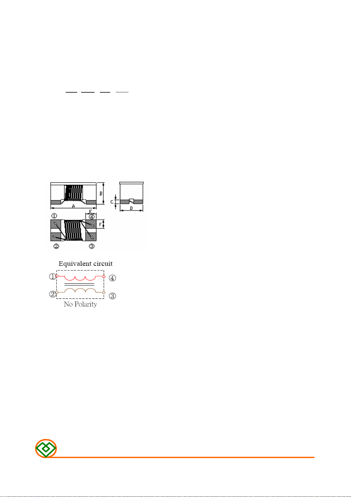
(1) SHAPES AND DIMENSIONS
(2) ELECTRICAL SPECIFICATIONS
(3) CHARACTERISTICS
for MCI-2012-SERIES-□□
PRODUCT INDENTIFICATION
MCI- 2012 - 900 -□□
① ② ③ ④
① Product Code
② Dimensions Code
③ Impedance Code
④ Inner Control Code
A: 2.0±0.20 mm
B: 1.2±0.20 mm
C: 0.17 Typ. mm
D: 1.2±0.20 mm
E: 0.45 Typ. mm
F: 0.40 Typ. mm
SEE TABLE 1
TEST INSTRUMENTS
Z : HP 4291B IMPEDANCE ANALYZER (or equivalent)
RDC : CHROMA MODEL 16502 MILLIOHMMETER (or equivalent)
I.R : CHROMA MODEL 19073 AC/DC/IR HIPOT TESTER (or equivalent)
(3)-1 Temperature rise ...................... +20℃ Max.
(3)-2 Ambient temperature ................ +60℃ Max.
(3)-3 Operate temperature range …... -25℃~+85℃
(Including self temp. rise)
(3)-4 Storage temperature range ...... -40℃~+85℃
MAG.LAYERS
MCI-2012-SERIES Page 1/7
Page 2
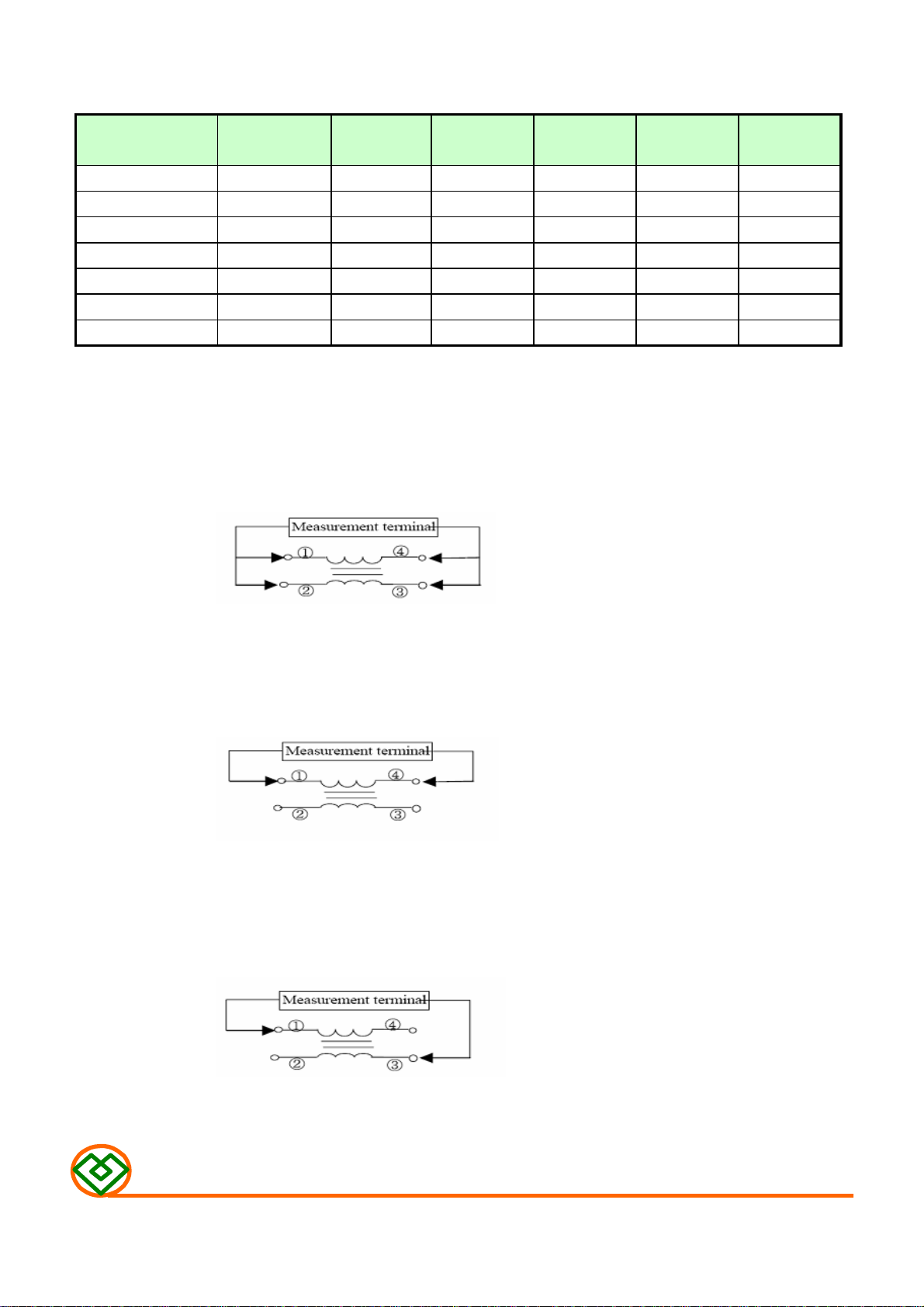
TABLE 1
MAGLAYERS
PT/NO.
MCI-2012-670 67 ±25% 0.25 50 400 125 10
MCI-2012-900 90 ±25% 0.35 50 330 125 10
MCI-2012-121 120±25% 0.30 50 370 125 10
MCI-2012-181 180±25% 0.35 50 330 125 10
MCI-2012-201 200±25% 0.35 50 330 125 10
MCI-2012-261 260±25% 0.40 50 300 125 10
MCI-2012-371 370±25% 0.40 50 280 125 10
Impedance Z(Ω)
@ 100MHz/0.5V
RDC (Ω)
Max.
Rated Voltage
Vdc(V)
Idc
Max.(mA)
Withstanding
Voltage
Vdc(V)
TEST EQUIPMENT
1. Impedance
Measured by using HP 4291B RF Impedance Analyzer.
Insulation
Resistance
(MΩ)Min.
2. DC Resistance
Measured by using Chroma 16502 mill ohm meter
3. Insulation Resistance
Measured by using Chroma 19073
Measurement voltage: 50v, Measurement time: 60 sec.
MAG.LAYERS
MCI-2012-SERIES Page-2/7
Page 3
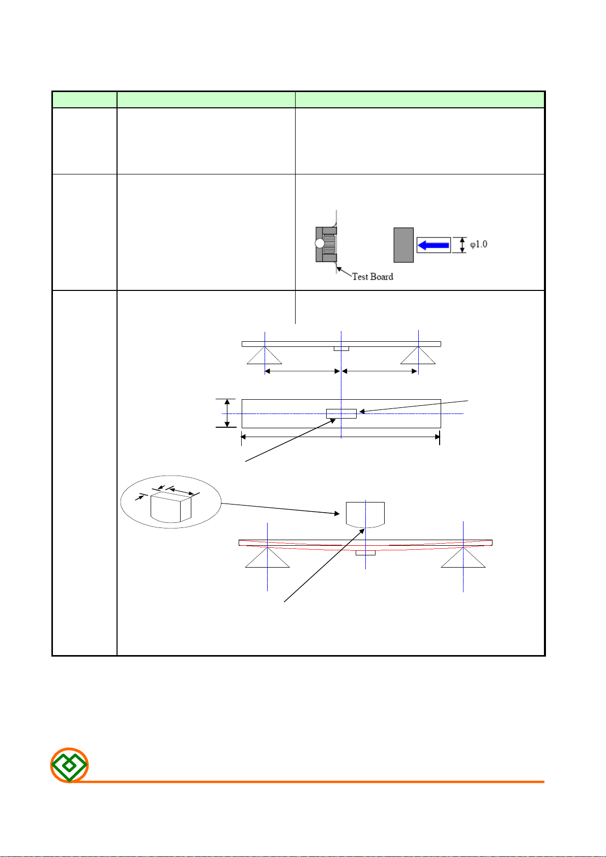
(4) RELIABILITY TEST METHOD
Item
Solder ability It can be connected on the Apply cream solder to the test circuit board .
Recommendation soldering condition. It is mounted on the recommendation soldering condition.
Terminal The terminal electrode and the ferrite Solder a chip to test substrate , and then laterally
strength must not be damaged. apply a load 0.5Kg in the arrow direction.
The terminal electrode and the ferrite Soldering a chip to a test substrate ,
must not be damaged. bend the substrate by 2mm and then return.
Specifications Test conditions
Dip pads in flux and dip in solder pot ( 96.5 Sn/3.5 Ag
solder) at 260°C ±5°C.
45
40
45
Width side
Strength on
pc board
bending
10
100
length
20
R10
Test board : Glass base epoxy multiplayer board pc board pattern.
PC board pattern : Recommended PC board pattern.
Force
Dimensions in mm
MAG.LAYERS
MCI-2012-SERIES
Page-3/7
Page 4

Item Specifications Test conditions
Temperature : +85±2℃
Applied voltage : Rated voltage
High
temperature
Applied current : Rated current
Testing time : 500±12 hours
Measurement :After placing for 24 hours min.
Temperature : +85±2℃
Humidity : 90 to 95%RH
Humidity
resistance
Thermal shock
Appearance : Ferrite shall not be
damaged.
Impedance:Within±20% of the
initial value.
insulation resistance: >10(MΩ)
DC resistance : standard value
inside.
Applied current : Rated current
Applied voltage : Rated voltage
Testing time : 500±12 hours
Measurement :After placing for 24 hours min.
Temperature : -25℃,+85℃
kept stabilized for 30 minutes each.
Cycle : 100 cycle
Measurement :After placing for 24 hours min.
1 cycle
30 min.
+85℃
30 sec
-40℃
30 min.
Low
temperature Testing time : 500±12 hours
Storage Measurement :After placing for 24 hours min.
Vibration
Appearance : Ferrite shall not be
damaged.
Temperature : -25±2℃
Frequency : 10 to 50 Hz
Amplitude : 1.52 mm
Dimension and times : X ,Y and Z directions
for 2 hours each.
MAG.LAYERS
MCI-2012-SERIES Page-4/7
Page 5

(5) RECOMMENDED SOLDERING CONDITIONS
(Please use this product by reflow soldering)
(5)-1 RECOMMENDED FOOTPRINT
Unit: mm
(5)-2 RECOMMENED REFLOW PATTERN
Temperature(℃ )
300
260
200
150
100
50
Preheating
Solding
260℃
Natural Cooling
10 sec1 to 4 min. more than 2 min.
(5)-3 IRON SOLDERING
Use a solder iron of less than 30W when soldering ,do not allow the soldering
iron tip directly touch the Ceramic body outside of terminal electrode.
3 seconds max. at 260℃.
Time
MAG.LAYERS
MCI-2012-SERIES Page-5/7
Page 6

(6) PACKAGING
W : 8.0
P : 4.0
P0 : 4.0
P1 : 2.0
(6)-1 CARRIER TAPE DIMENSIONS (mm)
P
1
mm
mm
mm
mm
W
P
P
0
(6)-2 TAPING DIMENSIONS (mm)
There shall not continuation more than two vacancies of the product.
(360 mm)
Leader.
ChipBlank
(50 pitches)
Blank
(70 pitches)
(6)-3 REEL DIMENSIONS
C
MAG.LAYERS
D
A : 180 mm
B : 60 mm
C : 13 mm
AB
D : 12 mm
E : 8.4 mm
E
MCI-2012-SERIES
Page-6/7
Page 7

(6)-4 COVER TAPE PEEL STRENGTH
The force for tearing off cover tape is 0.1~0.6(N) in the arrow direction at
the following conditions:
Temperature : 5 ~ 35℃
Humidity : 45 ~ 85%
Atmospheric pressure : 860 ~ 1060 hpa
160 ~ 180
。
Top cover tape
Base tape
(6)-5 QUANTITY
2000 pcs/Reel
(6)-6 The products are packaged so that no damage will be sustained.
(7) ATTENTION IN CASE OF USING
In case of using product ,please avoid following matters:
Splashing water or salt water
Dew condenses
Toxic gas (Hydrogen sulfide, Sulfurous acid ,Chlorine, Ammonia)
Vibrations or shocks which exceed the specified condition
Please be careful for the stress to this product by board flexure or something
after the mounting.
MAG.LAYERS
MCI-2012-SERIES
Page-7/7
Page 8

TYPICAL ELECTRICAL CHARACTERISTICS
1000
100
10
Common Mode
Differential Mode
Impedance(Ω)
MCI-2012-670
1
0.1
1 10 100 1000
Frequency(MHz)
MCI-2012-121
1000
100
Common Mode
Differential Mode
MCI-2012-900
10000
1000
100
10
Impedance(Ω)
1
0.1
1 10 100 1000
10000
1000
Common mode
Differential mode
Frequency(MHz)
MCI-2012-181
Common Mode
Differential Mode
10
Impedance(Ω)
1
0.1
1 10 100 1000
Frequency(MHz)
100
10
Impedance(Ω)
1
0.1
1 10 100 1000
Frequency(MHz)
MAG.LAYERS
MCI-2012-SERIES
ATTACHMENT-1
Page 9

TYPICAL ELECTRICAL CHARACTERISTICS
Common Mode
1000
10000
1000
MCI-2012-201
100
10
Impedance(Ω)
1
1 10 100 1000
Frequency(MHz)
MIC-2012-371
Common Mode
Differential Mode
MCI-2012-261
10000
1000
100
10
Common Mode
Differential Mode
Impedance(Ω)
1
0.1
1 10 100 1000
Frequency(MHz)
100
10
Impedance(Ω)
1
0.1
1 10 100 1000
Frequency(MHz)
MAG.LAYERS
MCI-2012-SERIES
ATTACHMENT-2
 Loading...