

Page 1
SCOPE
:
This specification applies to the current type Radial Leaded Inductor
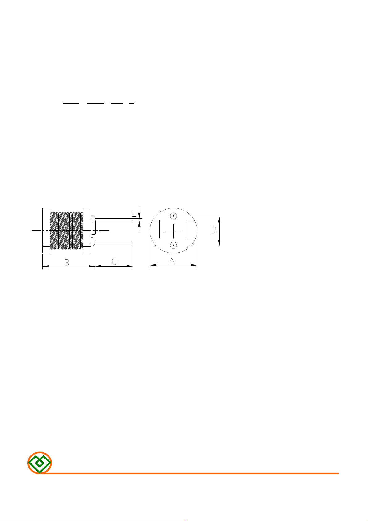
(1) SHAPES AND DIMENSIONS
(2) ELECTRICAL SPECIFICATIONS
(3) CHARACTERISTICS
for MCD-855C-SERIES
PRODUCT INDENTIFICATION
MCD - 855C - 220 K
① ② ③ ④
① Product Code
② Dimensions Code
③ Inductance Code
④ Tolerance Code
A : 7.8±0.5 mm
B : 6.5 Max. mm
C : 15±2.0 mm
D : 5.0±0.5 mm
E : φ0.65±0.1 mm
SEE TABLE 1
TEST INSTRUMENTS
L : HP 4284A PRECISION LCR METER (or equivalent)
RDC : CHROMA MODEL 16502 MILLIOHMMETER (or equivalent)
(3)-1 Ambient temperature ……......... +60℃ Max.
(3)-2 Operate temperature range ...... -40℃~+125℃
(Including self temp. rise)
(3)-3 Storage temperature range ...... -40℃~+125℃
MAG.LAYERS
MCD-855C-SERIES
Page 1/4
Page 2
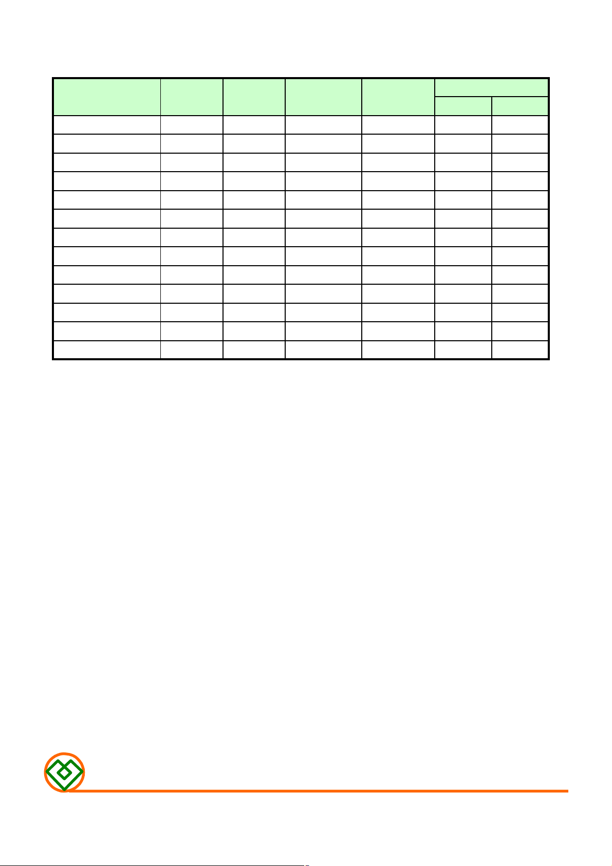
TABLE 1
MAGLAYERS
Inductance Percent Test Resistance Rated DC Current
PT/NO.
MCD-855C-150□
MCD-855C-220□
MCD-855C-330□
MCD-855C-121□
MCD-855C-331□
MCD-855C-471□
MCD-855C-821□
MCD-855C-102□
MCD-855C-122□
MCD-855C-152□
MCD-855C-182□
MCD-855C-222□
MCD-855C-682□
※ □ Specify the inductance tolerance,J(±5%),K(±10%),M(±20%)
L(μH) Tolerance Frequency RDC(Ω)Max. IDC1(A) IDC2(A)
15 K,M 100kHz/0.25V 90m 2.1 2.1
22 K,M 100kHz/0.25V 0.12 1.7 1.9
33 K,M 100kHz/0.25V 0.17 1.4 1.8
120 K,M 100kHz/0.25V 0.59 0.76 0.80
330 K,M 100kHz/0.25V 1.47 0.44 0.52
470 K,M 100kHz/0.25V 1.95 0.38 0.43
820 K,M 100kHz/0.25V 3.82 0.31 0.32
1000 K,M 100kHz/0.25V 5.28 0.25 0.30
1200 J,K 1kHz/0.25V 6.03 0.23 0.26
1500 J,K 1kHz/0.25V 7.15 0.21 0.25
1800 J,K 1kHz/0.25V 8.26 0.20 0.23
2200 J,K 1kHz/0.25V 11.1 0.18 0.18
6800 J,K 1kHz/0.25V 31.7 0.098 0.11
※ IDC1: Based on inductance change (△L/Lo:drop 10% Max.) @ ambient temp. 25℃
IDC2: Based on temperature rise (△T: 40℃ TYP.)
Rated DC Current: The less value which is IDC1 or IDC2.
MAG.LAYERS
MCD-855C-SERIES
Page 2/4
Page 3

(4) RELIABILITY TEST METHOD
MECHANICAL
NO. ITEMS
1 Solderability test
2 lead tensile 1.0 Kg MIN. The lead of product is pulled with a load of
strength test 1.0kg mininum until lead breakdown. The tensile
SPECIFICATIONS
More than 90% of the
termnial electrode
should be covered
with solder.
CONDITIONS
Dipping: 245 ± 5 ℃, 3 ± 1 seconds
force shall be recorded.
3 Vibration test
4 Soldering heat Visual:OK The leads of product are dipped into a solder pot
resistance test Circuit:OK
ENVIRONMENTAL
NO. ITEMS
1 Humidity
endurance
test
2 High temp
endurance test
△L/L≦±7%
Visual:OK
SPECIFICATIONS CONDITIONS
△L/L≦±5% The product is placed in a chamber of 40±2℃,
△L/L≦±5%
The product is fixed ento the vibration with
amplitude of 1.52m/m at a frequency of 10~55Hz
sweeping for lmin. The vibration is done at X,Y,
Z direction respectively for 2 houes, totally 6
hours.
of 260±5℃ for a duration of 10±1sec. Nothing
particular on visual and open circuitry as a
result of ore testing.
90~95%RH for 96 hours. Measurement is done
after the reaovery of 4~24 hours.
The product is placed in a chamber of 80±2℃,
for 72 hours. Measurement is done after recovery
of 4~24 hours.
3 Low temp test
4 Thermal shock
test
MAG.LAYERS
△L/L≦±5%
△L/L≦±5%
The product is placed in a chamber of -40±2℃,
for 96 hours. Measurement is done after
recovery of 4~24 hours.
The specimens are placed in a chamber and the
temp is then lowered to -20±2℃ for one hour.
The temp will raised to +80±2℃ for one hour.
This constitues one cycle. Ten cycles of such
testing shall be completed. Measurement is made
after recovery for 4~24 hours from the
completion of testing.
MCD-855C-SERIES
Page 3/4
Page 4

(5) PACKAGE SPECIFICATION (mm)
MAG.LAYERS
MCD-855C-SERIES
Page 4/4
 Loading...