

Page 1
SCOPE
:
This specification applies to the current type Radial Leaded Inductor
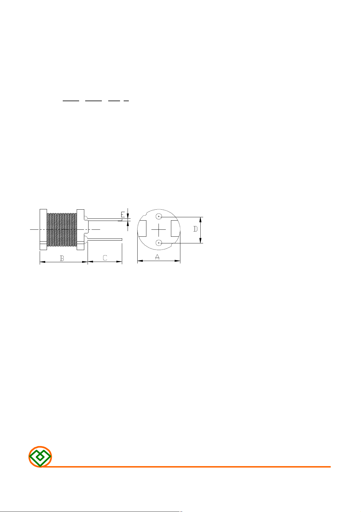
(1) SHAPES AND DIMENSIONS
(2) ELECTRICAL SPECIFICATIONS
SEE TABLE 1
(3) CHARACTERISTICS
for MCD-108C-SERIES
PRODUCT INDENTIFICATION
MCD - 108C - 102 K
① ② ③ ④
① Product Code
② Dimensions Code
③ Inductance Code
④ Tolerance Code
A: 10.0±0.5 mm
B: 8.5 Max. mm
C: 15.0±2.0 mm
D: 6.5±0.5 mm
E: φ0.65±0.1 mm
TEST INSTRUMENTS
L : HP 4284A PRECISION LCR METER (or equivalent)
RDC : CHROMA MODEL 16502 MILLIOHMMETER (or equivalent)
(3)-1 Ambient temperature ……......... +60℃ Max.
(3)-2 Operate temperature range ...... -40℃~+125℃
(Including self temp. rise)
(3)-3 Storage temperature range ...... -40℃~+125℃
MAG.LAYERS
MCD-108C-SERIES Page 1/4
Page 2
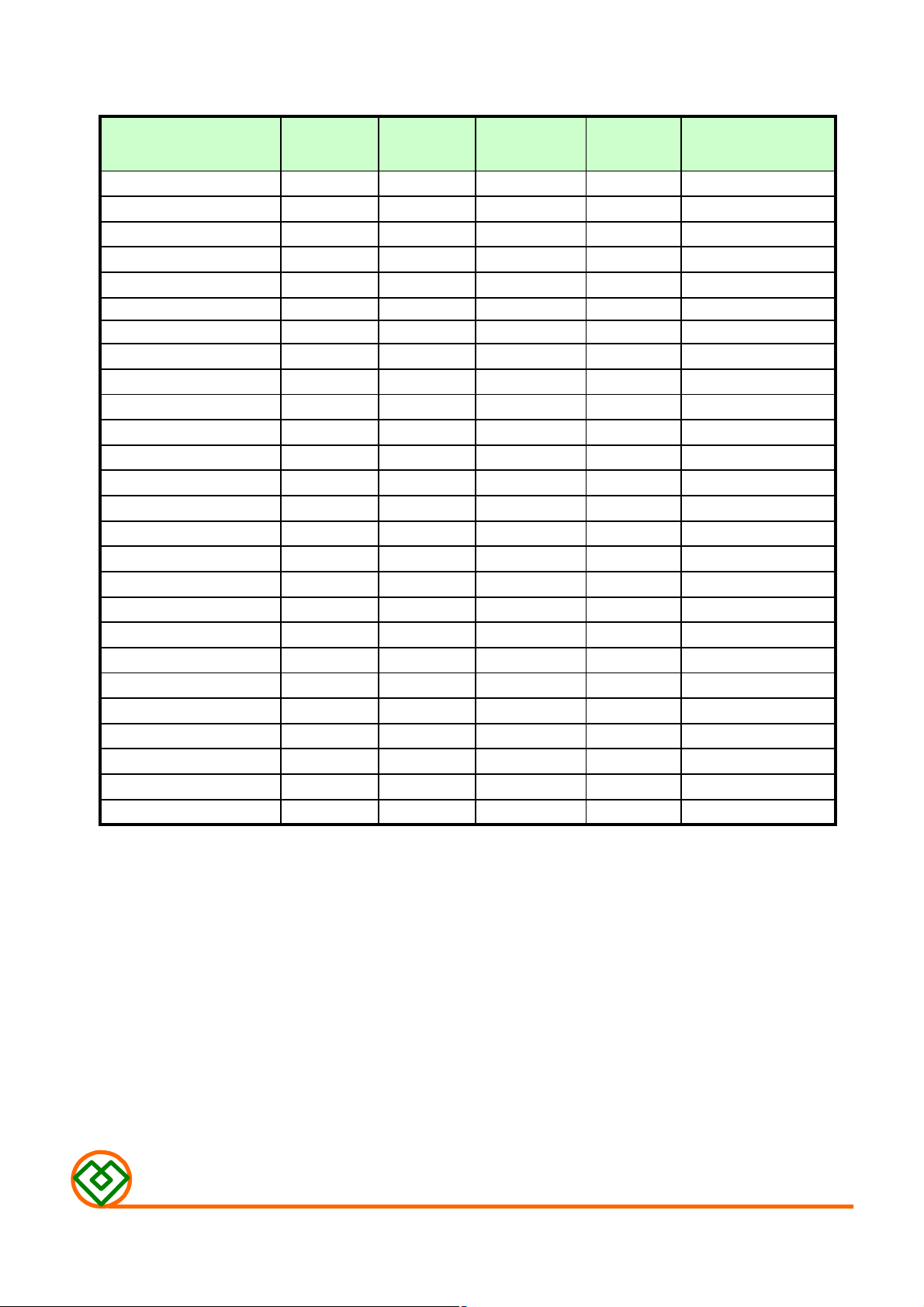
TABLE 1
MAGLAYERS
Inductance Percent Test Resistance Rated DC Current
PT/NO.
MCD-108C-100□
MCD-108C-120□
MCD-108C-150□
MCD-108C-180□
MCD-108C-220□
MCD-108C-270□
MCD-108C-330□
MCD-108C-390□
MCD-108C-470□
MCD-108C-560□
MCD-108C-680□
MCD-108C-820□
MCD-108C-101□
MCD-108C-121□
MCD-108C-151□
MCD-108C-181□
MCD-108C-201□
MCD-108C-221□
MCD-108C-271□
MCD-108C-331□
MCD-108C-391□
MCD-108C-471□
MCD-108C-561□
MCD-108C-681□
MCD-108C-821□
MCD-108C-102□
L(μH) Tolerance Frequency RDC(Ω)Max. IDC(A)
10 M 100kHz/0.25V 27m
12 M 100kHz/0.25V 31m
15 M 100kHz/0.25V 36m
18 M 100kHz/0.25V 49m
22 M 100kHz/0.25V 55m
27 M
33 K,M
39 K,M
47 K,M
56 K,M
68 K,M
82 K,M
100 K,M
120 K,M
150 K,M
180 K,M
200 K,M
220 K,M
270 K,M
330 K,M
390 K,M
470 K,M
560 K,M
680 K,M
820 K,M
1000 J,K
100kHz/0.25V
100kHz/0.25V
100kHz/0.25V
100kHz/0.25V
100kHz/0.25V
100kHz/0.25V
100kHz/0.25V
100kHz/0.25V
100kHz/0.25V
100kHz/0.25V
100kHz/0.25V
100kHz/0.25V
100kHz/0.25V
100kHz/0.25V
100kHz/0.25V
100kHz/0.25V
100kHz/0.25V
100kHz/0.25V
100kHz/0.25V
100kHz/0.25V
100kHz/0.25V
62m
79m
87m
99m
0.13
0.14
0.16
0.21
0.24
0.32
0.35
0.37
0.45
0.61
0.69
0.78
1.0
1.2
1.4
1.8
2.1
4.5
4.1
3.7
3.4
3.1
2.8
2.5
2.3
2.1
1.9
1.7
1.6
1.4
1.3
1.2
1.1
1.0
0.96
0.87
0.79
0.72
0.66
0.60
0.55
0.50
0.45
※ □ specify the inductance tolerance,J(±5%),K(±10%),M(±20%)
※ IDC : Based on inductance change (△L/Lo:drop 10% Max.) @ ambient temperature 25℃ and
Based on temperature rise (△T: 40℃ TYP.)
MAG.LAYERS
MCD-108C-SERIES
Page-2/4
Page 3

(4) RELIABILITY TEST METHOD
MECHANICAL
NO. ITEMS
More than 90% of the
1 Solderability test
2 lead tensile 1.0 Kg MIN. The lead of product is pulled with a load of
strength test 1.0kg mininum until lead breakdown. The tensile
termnial electrode
should be covered
with solder.
Dipping: 245 ± 5 ℃, 3 ± 1 seconds
force shall be recorded.
CONDITIONSSPECIFICATIONS
3 Vibration test
4 Soldering heat Visual:OK The leads of product are dipped into a solder pot
resistance test Circuit:OK
△L/L≦±7%
Visual:OK
The product is fixed ento the vibration with
amplitude of 1.52m/m at a frequency of 10~55Hz
sweeping for lmin. The vibration is done at X,Y,
Z direction respectively for 2 houes, totally 6
hours.
of 260±5℃ for a duration of 10±1sec. Nothing
particular on visual and open circuitry as a
result of ore testing.
ENVIRONMENTAL
NO. ITEMS
1 Humidity
endurance
test
2 High temp
endurance test for 72 hours. Measurement is done after recovery
SPECIFICATIONS
△L/L≦±5% The product is placed in a chamber of 40±2℃,
90~95%RH for 96 hours. Measurement is done
after the reaovery of 4~24 hours.
△L/L≦±5% The product is placed in a chamber of 80±2℃,
of 4~24 hours.
CONDITIONS
3 Low temp test
4 Thermal shock
test
MAG.LAYERS
△L/L≦±5% The product is placed in a chamber of -40±2℃,
for 96 hours. Measurement is done after
recovery of 4~24 hours.
△L/L≦±5%
The specimens are placed in a chamber and the
temp is then lowered to -20±2℃ for one hour.
The temp will raised to +80±2℃ for one hour.
This constitues one cycle. Ten cycles of such
testing shall be completed. Measurement is made
after recovery for 4~24 hours from the
completion of testing.
MCD-108C-SERIES
Page-3/4
Page 4

(5) PACKAGE SPECIFICATION (mm)
MAG.LAYERS
MCD-108C-SERIES
Page-4/4
 Loading...