

Page 1
■
-
C
A
B
D
A
P
P
L
I
C
A
T
I
O
N
■
A
P
P
L
I
C
A
■
A
P
P
L
GMPI series is suitable for power line choke because of its excellent direct current
characteristics
PC/ Notebook
PDA
Digital camera
DVD
■
F
E
A
F
P
E
E
R
R
R
A
A
O
O
O
T
T
T
D
D
D
■
F
■
The GMPI series is magnetically shielded chip based on multilayer process.
New magnetic material is developed to get excellent direct current characteristics.
This series has larger rated current than conventional GMLI series.
Low DC resistance is realized.
The cross talk characteristics are excellent because of the magnetically shielded
structure.
■
P
■
P
■
I
U
U
U
C
U
U
U
R
R
R
A
C
C
C
E
E
E
T
T
T
T
T
S
S
S
I
O
N
I
O
N
I
D
E
N
T
I
F
I
C
A
T
I
O
N
I
D
E
N
T
I
F
I
C
A
I
D
E
N
T
I
F
T
I
C
A
T
I
O
N
I
O
N
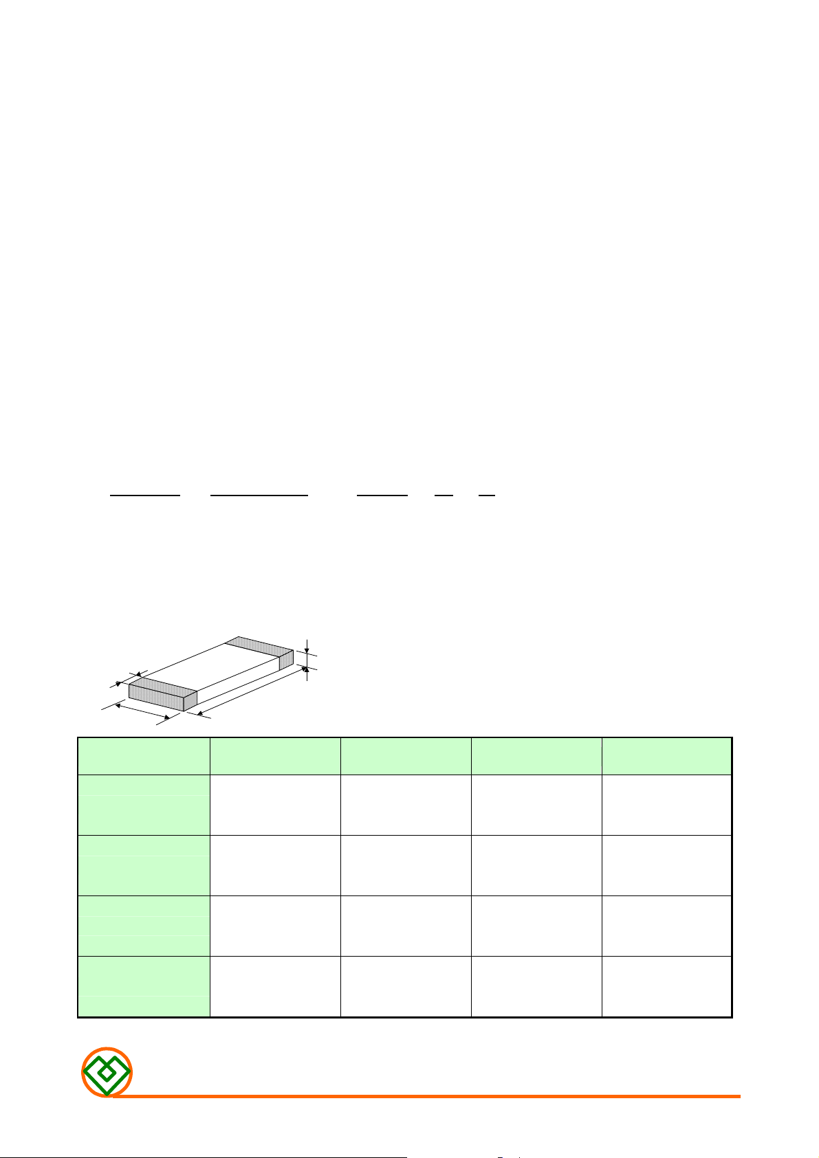
G M P I
Product Code Dimension Code
Inductance Tolerance Code : N = ±30%,M = ±20%
Code for Special Specification
■
P
R
O
■
P
■
P
PRODUCT NO.
GMPI-252010 2.5±0.20 2.0±0.20 1.0(MAX.) 0.5±0.30
GMPI-252012 2.5±0.20 2.0±0.20 1.2(MAX) 0.5±0.30
R
R
O
O
D
D
D
2 5 2 0 1 0 -
U
C
T
D
T
T
I
D
I
D
I
U
U
C
C
1 R 5 N
M
E
N
M
E
N
M
E
N
A B C D
S
S
S
I
O
I
O
I
O
N
N
N
T
NOTE:Dimensions in mm
GMPI-201610 2.0±0.20 1.6±0.20 1.0(MAX.) 0.5±0.30
GMPI-201209 2.0±0.20 1.2±0.20 1.0(MAX.) 0.5±0.30
MAG.LAYERS
GMPI-201610-F1 Series
Page 2

E
E
■ E
L
L
L
E
E
E
C
C
C
T
T
T
R
R
R
I
C
A
L
R
E
Q
U
I
R
E
M
E
N
T
I
C
A
L
R
E
Q
U
I
R
E
M
I
C
A
L
R
E
Q
U
I
R
E
M
E
E
N
N
T
T
S
S
S
Rated Current (mA)
Max.
IDC*1 IDC*2
M
M
M
E
E
E
Inductance
(μH)
T
H
O
H
H
O
O
D
D
D
T
T
Part Number
GMPI-201610-1R5MF1 1.5±20% 5 0.11 400 1100
GMPI-201610-2R2MF1 2.2±20% 5 0.11 300 1100
GMPI-201610-3R3MF1 3.3±20% 5 0.13 250 1000
GMPI-201610-4R7MF1 4.7±20% 5 0.16 150 900
IDC*1 Inductance change should be less than ±30% when rated current is applied.
IDC*2 Temperature rise should be less than 40℃
■
M
E
A
S
U
R
I
N
G
■
M
E
A
S
■
M
E
Test Instrument:
A
S
U
U
R
R
I
N
G
I
N
G
/
C
/
/
Test Freq.
(MHz)
O
N
C
O
N
C
O
N
D
D
D
RDC (Ω)
±30%
I
T
I
O
N
I
I
O
O
N
N
I
T
I
T
L/SRF: Agilent 4291B Impedance Analyzer, Test Fixture: Agilent 16192
RDC: Agilent 34401A
Test Condition:
< Unless otherwise specified >
Temperature: 15°C to 35°C Humidity: 25% to 85% RH
< In case of doubt >
Temperature: 25°C ± 2°C Humidity: 60% to 70% RH
Osc. Level: 100mV
MAG.LAYERS
GMPI-201610-F1 Series
Page 3
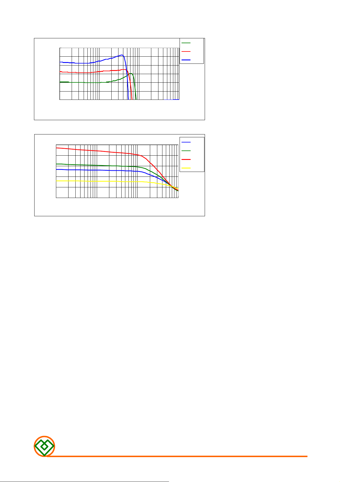
T
Indcuctance(uH)
Inductance(uH)
T
■ T
Y
Y
Y
P
P
P
I
C
A
L
E
L
E
C
T
R
I
C
A
L
C
H
A
R
A
C
T
E
R
I
S
T
I
C
S
(
T
=
2
5
℃℃℃℃
I
C
A
L
E
L
E
C
T
R
I
C
A
L
C
H
A
R
A
C
T
E
R
I
S
T
I
C
S
(
T
=
I
C
A
L
E
L
E
C
T
R
I
C
A
L
C
H
A
R
A
C
T
E
R
I
S
T
I
C
S
2
(
T
=
2
5
5
℃℃℃℃
℃℃℃℃
)
)
)
■
■
■
6.0
5.0
4.0
3.0
2.0
1.0
0.0
1 10 100 1000
T
Y
P
I
C
P
P
A
I
C
A
I
C
A
T
Y
T
Y
5.0
4.0
3.0
2.0
1.0
0.0
1 10 100 1000
GMPI-201610-Series
Frequency(MHz)
L
D
C
B
L
L
D
D
I
C
B
I
C
B
I
GMPI-201610 Series
DC Current(mA)
A
A
A
S
S
S
C
H
A
R
A
A
R
R
A
A
A
C
H
C
H
C
C
C
T
T
T
E
E
E
R
R
R
2R2
3R3
4R7
I
S
T
I
C
S
C
C
S
S
I
S
T
I
I
S
T
I
2R2
3R3
4R7
1R5
MAG.LAYERS
GMPI-201610-F1 Series
Page 4
■
P
A
■
■
C
P
A
C
P
A
C
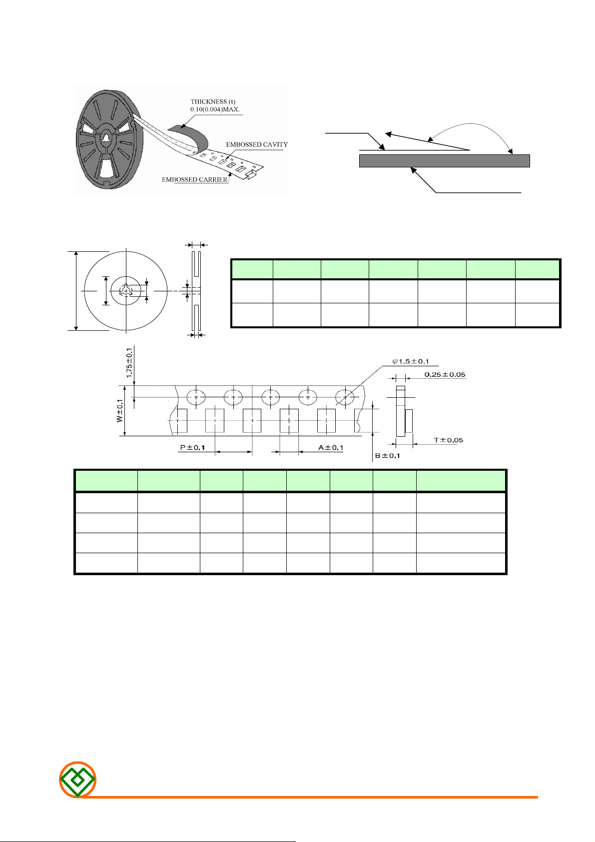
Peel-off Force
K
K
K
A
A
A
G
G
G
I
N
G
I
N
G
I
N
G
The force for peeling off cover tape is 10 grams in the arrow direction.
Dimension (Unit: mm)
F
A
B
C
D
TOP COVER TAPE
TYPE
8 mm 178±1
12 mm 178±0.3 60 ±0.2 19.3 ±0.1 13.5 ±0.1 13.6 ±0.1
E
A
B
60 +0.5
-0
C D E
- 13 ±0.2 9 ±0.5 12 ±0.5
165° TO 180°
BASE TAPE
F
-
TYPE SIZE A B W P T CHIPS/REEL
GMPI
GMPI
GMPI
GMPI
252012 2.27 2.74 8 4 1.40
252010 2.20 2.90 8 4 1.20
201610 1.90 2.30 8 4 1.20
201209 1.42 2.25 8 4 1.00,
3000
3000
3000
4000
MAG.LAYERS
GMPI-201610-F1 Series
Page 5
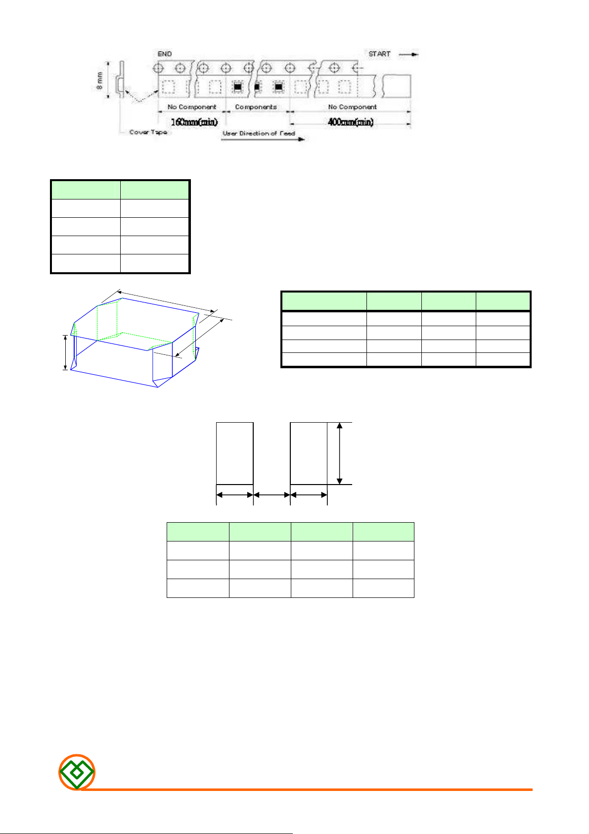
Taping Quantity
SERIES PCS/Reel
252012 3000
252010 3000
201209 4000
201610 3000
Tape Packing Case
W
H
`
■
R
E
C
O
M
M
E
N
■
■
R
E
C
O
M
R
E
C
O
M
M
M
E
E
N
N
D
D
D
E
E
E
D
D
D
No. of Reels
2
E
E
E
R
R
R
3
4
5
N
N
N
S
S
S
L
L
A
N
D
P
A
T
L
A
N
D
N
D
P
L
A
P
A
A
T
T
T
T
T
W
18±0.5 18±0.5 2.4±0.2
18±0.5 18±0.5 3.6±0.2
18±0.5 18±0.5 4.8±0.2
18±0.5 18±0.5 6.0±0.2
L H
Unit: cm
B A A
Type 2520 2016 2012
A 0.8 0.7 0.7
B 1.2 0.8 0.8
C 2.2 1.8 1.45
C
Unit: mm
MAG.LAYERS
GMPI-201610-F1 Series
Page 6
■
More than 90% of the terminal electrode shall
More than 75% of the terminal electrode shall
R
E
L
I
A
B
I
L
T
Y
T
E
S
T
■
■
R
E
L
I
A
B
I
L
T
Y
T
R
E
L
I
A
B
I
L
T
Y
E
T
E
S
S
T
T
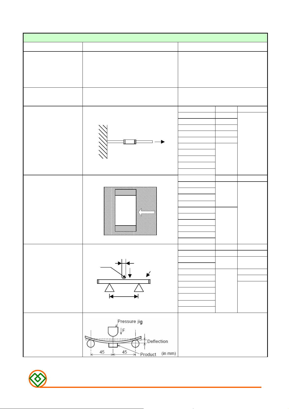
•MECHANICAL PERFORMANCE TEST
ITEM SPECIFICATION TEST CONDITION
be covered with fresh solder.
Solderability
The chip shall not crack.
Soldering Heat Resistance
be covered with solder.
The terminal electrode shall not be broken off
nor the ferrite damaged.
Terminal Strength
The terminal electrode shall not be broken off
nor the ferrite damaged.
W
Terminal Strength
No mechanical damage.
The ferrite shall not be damaged.
R0.5
1.0
P
Bending Strength
A
Appearance: No damage
Bending Test
W
Chip
Solder:
Sn-3.0Ag-0.5Cu
Solder Temperature:
245 ± 5℃
Flux: Rosin
Dip Time: 3 ± 1 Seconds
Solder temperature : 260 ± 5℃
Flux: Rosin
Dip time: 10 ± 1 seconds
TYPE W(KGF) Time (Sec)
GMPI-160808 0.6
GMPI-201205 0.8
GMPI-201209 0.6
GMPI-201610 1.0
GMPI-252005 1.5
GMPI-252010
GMPI-252012
GMPI-321608
GMPI-322510
GMPI-322512
TYPE W(KGF) Time (Sec)
GMPI-160808
GMPI-201205
GMPI-201209
GMPI-201610
GMPI-252005
GMPI-252010
GMPI-252012
GMPI-321608
GMPI-322510
GMPI-322512
TYPE A(MM)
GMPI-160808 1.0 0.6
GMPI-201205
GMPI-201209
GMPI-201610 2.0
GMPI-252005 1.0
GMPI-252010
GMPI-252012
GMPI-321608
GMPI-322510
GMPI-322512
Substrate:PCB(100mm×40mm×1.6mm)
Solder: Reflow
Speed of Applying Force: 0.5mm / s
Deflection: 2mm
Hold Duration: 30 s
1.0
1.0
2.0
1.4 1.0
2.0
30±5
10±5
P(KGF)
2.0
MAG.LAYERS
GMPI-201610-F1 Series
Page 7

Vibration
initial
and humidity should be less than
Drop shock
• CLIMATIC TEST
ITEM SPECIFICATION TEST CONDITION
Thermal Shock
(Temperature Cycle)
Humidity Resistance
△L/Lo≦±5%
There shall be no mechanical damage.
No apparent damage
No mechanical damage.
Inductance shall be within ± 5% of the initial
value, and Q (shall be) within ± 30% of the
value.
The sample shall be soldered onto the
printed circuit board and when a vibration
having an amplitude of 1.52mm and a
frequency of from 10 to 55Hz/1 minute
repeated should be applied to the 3
directions (X,Y,Z) for 2 hours each.
Dropped onto printed circuit board from
100cm height three times in x, y, z
directions. The terminals shall be protected.
Temperature: -40℃,85℃ for 30 minutes
each, 100 cycles.
Temperature : 40℃
Humidity: 95% RH
Time: 1000 ± 12 HOURS
High Temperature
Resistance
Low Temperature
Resistance
1. Operating Temperature Range: -55 ℃ TO +125℃
2. Storage Condition: The temperature should be within -40℃~85℃
75% RH. The product should be used within 6 months from the time of delivery.
Temperature: 85℃±2℃
Time: 1000 ± 12 hours
Temperature : -40℃±2℃
Time: 1000 ± 12 hours
MAG.LAYERS
GMPI-201610-F1 Series
Page 8

■
■
■
R
E
C
O
M
M
E
N
D
E
D
R
E
F
L
O
W
S
O
L
D
E
R
I
N
G
P
R
O
F
I
L
E
R
E
C
O
M
M
E
N
D
E
D
R
E
F
L
O
W
S
O
L
D
E
R
I
N
G
P
R
O
R
E
C
O
M
M
E
N
D
E
D
R
E
F
L
O
W
S
O
L
D
E
R
I
N
G
P
t
P
T
P
Ramp-up
T
L
T
s
max
T
s
Temperature
min
t=25
t
S
Preheat
℃℃℃℃
to Peak
Time
t
L
Critical Zone
F
R
O
F
TL to T
Ramp-down
I
L
E
I
L
E
P
■
■
■
Profile Feature Sn-Pb Pb-Free
ts 60~120 seconds 60~180 seconds
Preheat
Average ramp-up rate (T
Time main above
Peak temperature (TP)
Time within 5℃ of actual peak
temperature (tP)
Ramp-down rate
Time 25℃ to peak temperature
N
O
T
E
S
N
O
T
N
O
T
E
E
S
S
T
smin
T
smax
smax
Temperature (TL)
Time (tL) 60~150 seconds 60~150 seconds
to TP)
100℃ 150℃
150℃ 200℃
3℃/second max. 3℃/second max.
183℃ 217℃
230℃ 250~260℃
10 seconds 10 seconds
6℃/sec max. 6℃/sec max.
6 minutes max. 8 minutes max.
The contents of this data sheet are subject to change without notice. Please
confirm the specifications and delivery conditions when placing your order.
MAG.LAYERS
GMPI-201610-F1 Series
 Loading...