

Page 1

■
A
P
P
L
I
C
A
T
I
O
N
■
A
P
P
L
I
C
A
■
A
P
P
L
GMLB chip beads can be used in a variety of electronic applications
including:
Computers and Computer Peripherals
Cellular Communication Equipment
Digital Cameras
Digital Televisions
Audio Equipment
■
F
E
A
■
F
■
the latest in multilayer technology, we have developed chip beads that are able
to resolve all EMI/EMC issues. High quality, reliability, and versatility make the
GMLB series chip beads suitable for all your design needs.
High Reliability
T
E
A
F
T
E
A
T
The GMLB Series is Mag.Layers’ line of high quality ferrite chip beads. Using
The monolithic inorganic materials used to construct GMLB chips restrain magnetic
flux leakage thereby minimizing EMI concerns. GMLB chips are also extremely
effective with unstable grounding.
I
U
U
U
C
R
R
R
A
E
E
E
T
T
S
S
S
I
O
N
I
O
N
Small Chip-Shaped Design
The chip-shaped design makes GMLB chip beads ideal for automatic mounting.
High Soldering Heat Resistance
High quality termination allows both flow and re-flow soldering methods to be
applied.
Sharp High Frequency Characteristics
The GMLB high frequency chip series has sharp impedance characteristics, which
make it suitable for high-speed signal lines.
■
P
R
O
D
U
C
T
I
D
E
N
T
I
F
I
C
A
T
I
O
N
■
P
R
O
D
U
C
T
I
D
E
N
T
I
F
I
C
A
■
P
R
O
D
U
C
T
I
D
E
N
T
I
G M L B - 1 0 0 5 0 5 - 0 0 3 0 A - N 8
Product Code
Dimension Code
Impedance (at 100 MHz)
Series Type
F
T
I
C
A
T
I
O
N
I
O
N
□
□
□□
Design Code
Code for Special Specification
MAG.LAYERS
GMLB-100505-W Series
Page 2
■
P
R
O
D
U
C
T
D
I
M
E
N
S
I
O
N
■
P
R
O
D
U
C
T
D
I
M
E
N
■
P
R
O
D
U
C
T
D
I
M
D
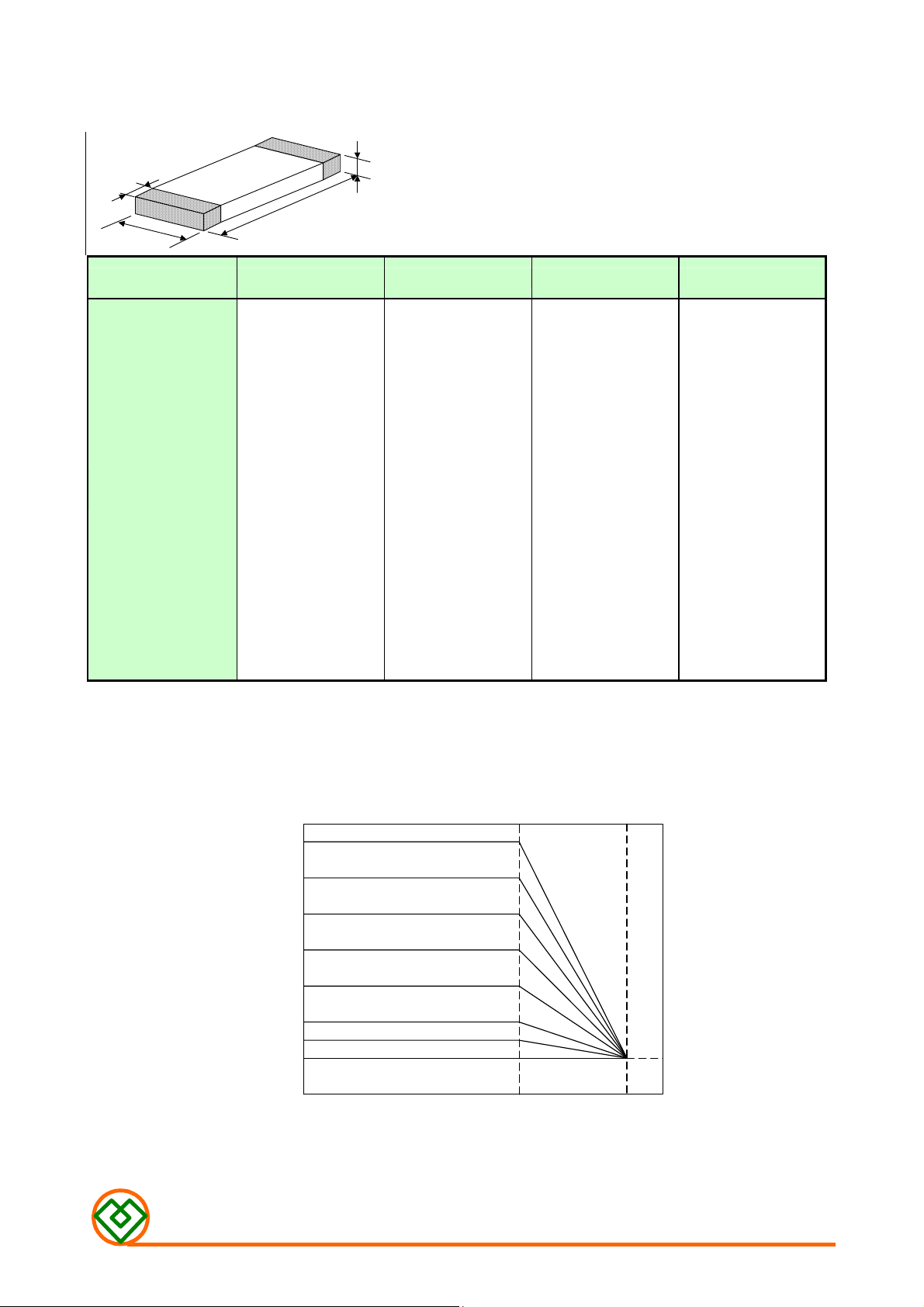
B
PRODUCT NO. A B C D
S
E
N
S
A
I
O
N
I
O
N
C
NOTE:Dimensions in mm
GMLB-100505
(0402)
■
C
U
R
R
E
N
■
C
U
R
■
C
In operating temperatures exceeding +85℃, derating of current is necessary for chip
ferrite beads for which rated current is 1.5A or over. Please apply the derating curve
shown below according to the operating temperature.
U
R
R
R
E
E
N
N
T
T
T
1.0±0.10
(0.039±0.004)
D
E
R
A
R
R
7
6
5
A
A
T
T
T
D
E
D
E
0.5±0.10
(0.019±0.004)
I
N
G
I
N
G
I
N
G
0.5±0.10
(0.019±0.004)
0.25±0.10
(0.0095±0.004)
4
3
Rated Current (A)
2
1.5
1
Operating Temperature(℃)
85 125
MAG.LAYERS
GMLB-100505-W Series
Page 3

E
L
E
C
T
R
I
C
A
L
R
E
Q
U
I
R
E
M
E
N
T
E
L
E
C
T
R
I
C
A
L
R
E
Q
U
I
R
E
M
■ E
L
E
C
T
R
I
C
A
L
R
E
Q
U
I
R
Part Number
GMLB-100505-0120W-N8 120±25% 0.70 300
Impedance (Ω)
at 100 MHz
E
M
E
E
N
N
T
T
S
S
S
RDC (Ω)
Max.
I
(mA)
DC
Max.
Operating
Temp. Range (℃)
GMLB-100505-0220W-N8 220±25% 1.00 250
GMLB-100505-0600W-N8 600±25% 0.85 300
GMLB-100505-1000W-N8 1000±25% 1.20 250
Temperature rise should be less than 40℃ for P-type and less than 25℃ for other
types when rated current is applied.
■
M
E
A
S
U
R
I
N
G
M
E
T
H
O
D
/
C
O
N
D
I
T
I
O
N
■
M
E
A
S
U
R
I
N
G
■
M
E
A
S
U
R
I
Test Instrument:
Z:
Agilent 4291B Impedance Analyzer, Test Fixture: Agilent 16192
Osc. Level: 500mV
RDC: Agilent 34401A
Test Condition:
< Unless otherwise specified >
Temperature: 15°C to 35°C Humidity: 25% to 85% RH
< In case of doubt >
Temperature: 25°C ± 2°C Humidity: 60% to 70% RH
N
G
M
M
E
E
T
T
H
H
O
O
D
D
/
C
O
N
D
I
/
C
O
N
D
T
I
T
I
I
O
O
N
N
-55 ~ +125
MAG.LAYERS
GMLB-100505-W Series
Page 4

■
■
■
T
Y
P
I
C
A
L
E
L
E
C
T
R
I
C
A
L
C
H
A
R
A
C
T
E
R
I
S
T
I
C
S
(
T
====
2
5
℃℃℃℃
)
T
Y
P
I
C
A
L
E
L
E
C
T
R
I
C
A
L
C
H
A
R
A
C
T
E
R
I
S
T
I
C
S
(
T
====
T
Y
P
I
C
A
L
E
L
E
C
T
R
I
C
A
L
C
H
A
R
A
C
T
E
R
I
S
T
I
C
S
(
2
T
====
2
5
5
℃℃℃℃
℃℃℃℃
)
)
GMLB-100505-0120W-N8
250
200
150
100
50
Im pedance(ohm )
0
1 10 100 1000
GMLB-100505-1000W-N8
Frequency(MHz)
Z
X
R
GMLB-100505-0220W-N8
GMLB-100505-0600W-N8
MAG.LAYERS
GMLB-100505-W Series
Page 5
■
P
■
■
A
P
A
P
A
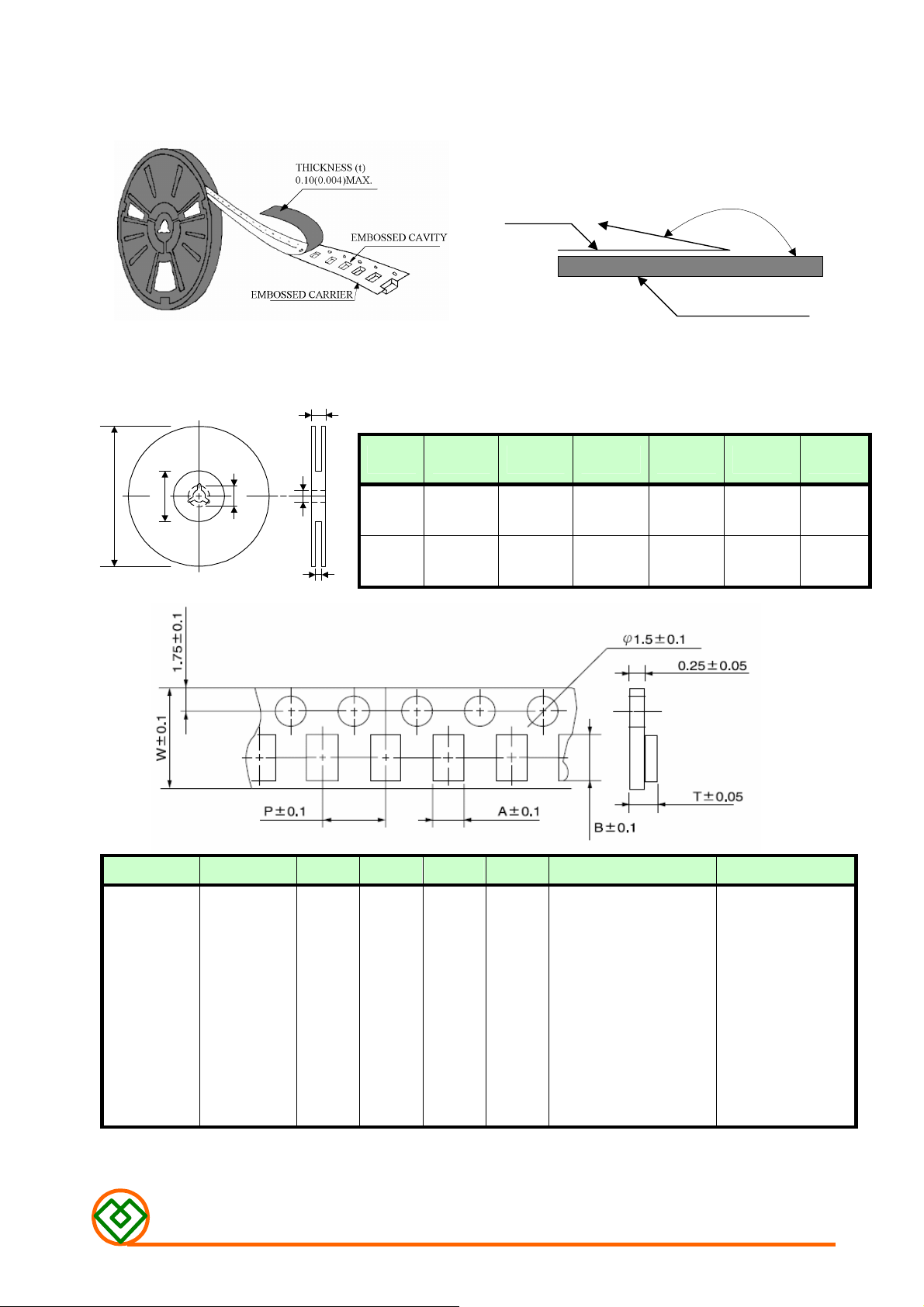
Peel-off Force
C
C
C
K
K
K
A
A
A
G
G
G
I
N
G
I
N
G
I
N
G
The force for peeling off cover tape is 10 grams in the arrow direction.
Dimension (Unit: mm)
A
B
C
D
TOP COVER TAPE
F
TYPE
8 mm 178±1
12 mm 178±0.3 60 ±0.2 19.3 ±0.1 13.5 ±0.1 13.6 ±0.1
E
A
B
60 +0.5
-0
C D E
- 13 ±0.2 9 ±0.5 12 ±0.5
165° TO 180°
BASE TAPE
F
-
TYPE SIZE A B W P T CHIPS/REEL
GMLB 100505 0.6 1.1 8 2 1.0 10000
MAG.LAYERS
GMLB-100505-W Series
Page 6

Taping Quantity
SERIES 1005
PCS/Reel 10000
Tape Packing Case
W
No. of
Reels
W
L H
H
■
■
■
2
L
`
3
4
5
18±0.5 18±0.5 2.4±0.2
18±0.5 18±0.5 3.6±0.2
18±0.5 18±0.5 4.8±0.2
18±0.5 18±0.5 6.0±0.2
Unit: cm
R
E
C
O
M
M
E
N
D
E
D
P
C
B
L
A
Y
O
U
T
R
E
C
O
M
M
E
N
D
E
D
P
C
B
L
A
Y
R
E
C
O
M
M
E
N
D
E
D
P
C
B
L
Solder-resist
C
Component
AB B
Type 1005
A
O
Y
O
pattern
U
U
Land
T
T
Component
W
L
Unit: mm
Size
MAG.LAYERS
L 1.0
W
A 0.45~0.55
B 0.40~0.50
C 0.40~0.50
0.5
GMLB-100505-W Series
Page 7

n 90% of the terminal electrode shall
n 75% of the terminal electrode shall
The sample shall be soldered onto the printed
and when a vibration having an
and a frequency of from
be
irections (X,Y,Z) for 2 hours
Dropped onto printed circuit board from
20% of the initial
W
R
E
L
I
A
B
I
L
T
Y
T
E
S
R
E
L
I
A
B
I
L
T
Y
R
E
L
I
A
B
I
•
Mechanical Performance Test
ITEM SPECIFICATION TEST CONDITION
Solderability
Soldering Heat Resistance
L
T
Y
More tha
be covered with fresh solder.
The chip shall not crack.
More tha
be covered with solder.
The terminal electrode shall not be broken off
nor the ferrite damaged.
T
T
E
E
S
S
T
T
T
Solder: 96.5Sn-3.0Ag-0.5Cu
Solder Temperature: 245 ± 5℃
Flux: Rosin
Dip Time: 3 ± 1 Seconds
Solder: 96.5Sn-3.0Ag-0.5Cu
Solder temperature : 260 ± 5℃
Flux: Rosin
Dip time: 10 ± 1 seconds
TYPE W(KGF) TIME (SEC)
Terminal Strength
Bending Strength
Bending Test
Vibration
Drop shock
No mechanical damage.
The ferrite shall not be damaged.
R0.5
Appearance: No damage
Impedance shall be within ± 20% of the initial
value.
There shall be no mechanical damage.
No apparent damage
1.0
Chip
P
A
GMLB-100505
TYPE A(MM) P(KGF)
GMLB-100505
Substrate: PCB(100mm×40mm×1.6mm)
Solder: Reflow
Speed of Applying Force: 0.5mm / s
Deflection: 2mm
Hold Duration: 30 s
circuit board
amplitude of 1.52mm
10 to 55Hz/1 minute repeated should
applied to the 3 d
each.
100cm height three times in x, y, z directions.
The terminals shall be protected.
0.2 30 ± 5
0.4
0.2
• Climatic test
ITEM SPECIFICATION TEST CONDITION
Thermal Shock
(Temperature Cycle)
Humidity Resistance
High Temperature
Resistance
Low Temperature
Resistance
1. Operating Temperature Range: -55 ℃ TO +125℃
2. Storage Condition: The temperature should be within -40℃~85℃ and humidity should be less than 75% RH.
The product should be used within 6 months from the time of delivery.
Impedance shall be within ±
value.
MAG.LAYERS
Temperature: -55℃~125℃ for 30 minutes
each, 100 cycles.
Temperature : 60℃
Humidity: 95% RH
Time: 1000 ± 12 Hours
Temperature : 85℃±2℃
Time: 1000 ± 12 Hours
Temperature : -40℃±2℃
Time: 1000 ± 12 Hours
GMLB-100505-W Series
Page 8
■
■
■
R
E
C
O
M
M
E
N
D
E
D
R
E
F
L
O
W
S
O
L
D
E
R
I
N
G
P
R
O
F
I
L
E
R
E
C
O
M
M
E
N
D
E
D
R
E
F
L
O
W
S
O
L
D
E
R
I
N
G
P
R
O
R
E
C
O
M
M
E
N
D
E
D
R
E
F
L
O
W
S
O
L
D
E
R
I
N
G
P
t
P
T
P
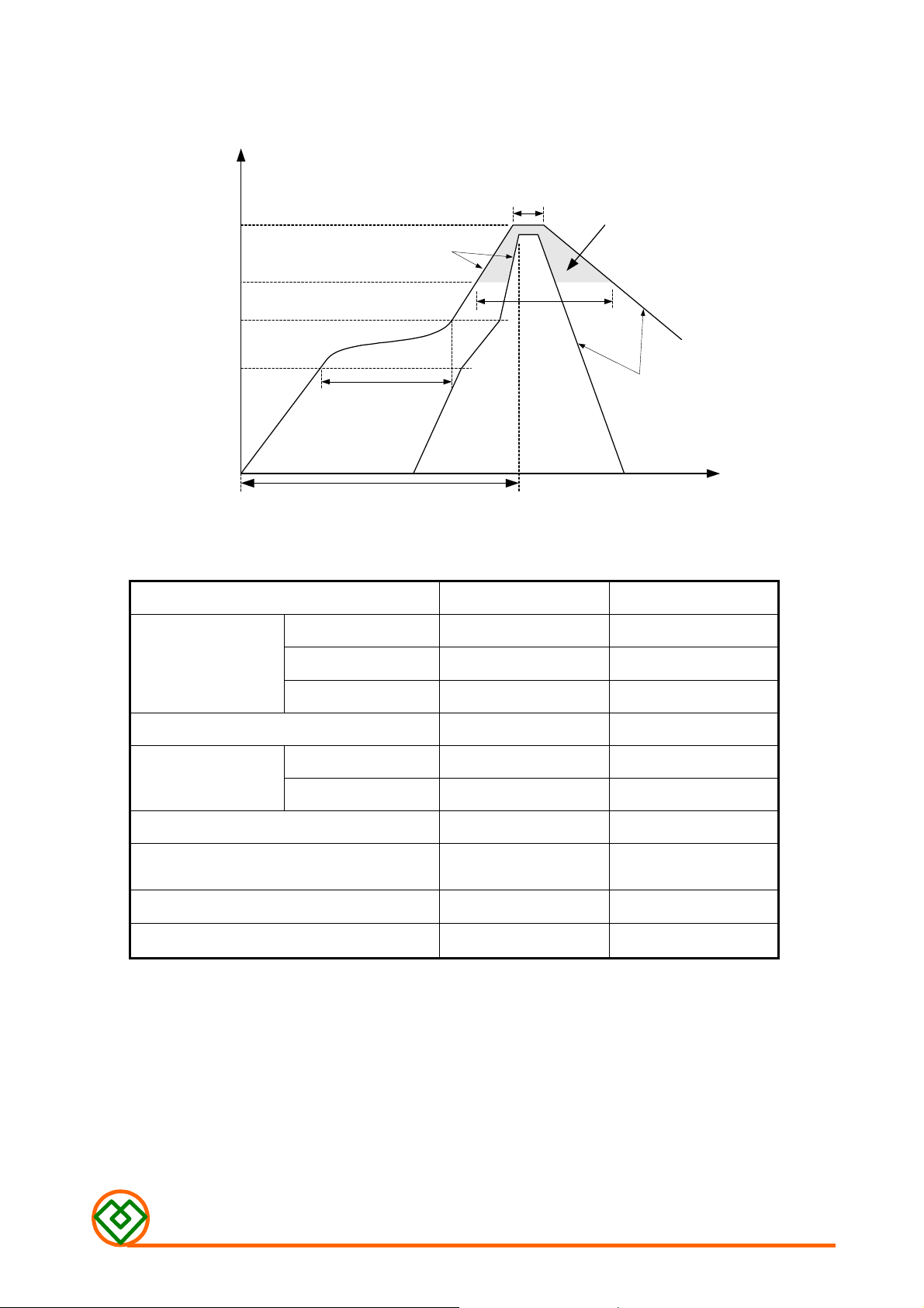
Ramp-up
T
L
T
s
max
T
s
Temperature
min
t=25
t
S
Preheat
℃℃℃℃
to Peak
Time
t
L
Critical Zone
F
R
O
F
TL to T
Ramp-down
I
L
E
I
L
E
P
Profile Feature Sn-Pb Pb-Free
ts 60~120 seconds 60~180 seconds
Preheat
Average ramp-up rate (T
Time main above
Peak temperature (TP)
Time within 5℃ of actual peak
temperature (tP)
Ramp-down rate
Time 25℃ to peak temperature
■
N
O
T
E
S
■
■
N
O
T
N
O
T
E
E
S
S
T
T
Temperature (TL)
Time (tL) 60~150 seconds 60~150 seconds
smin
smax
smax
to TP)
100℃ 150℃
150℃ 200℃
3℃/second max. 3℃/second max.
183℃ 217℃
230℃ 250~260℃
10 seconds 10 seconds
6℃/sec max. 6℃/sec max.
6 minutes max. 8 minutes max.
The contents of this data sheet are subject to change without notice. Please
confirm the specifications and delivery conditions when placing your order.
MAG.LAYERS
GMLB-100505-W Series
 Loading...