

Page 1

IMPORTANT FOR FUTURE REFERENCE
Please complete this information and retain this manual
for the life of the equipment:
Model #: ___________________________
Serial #: ___________________________
Date Purchased: ____________________
COMMERCIAL & RESIDENTIAL OUTDOOR COOKING
APPLIANCES
Installation & Operation Manual
MKO30, MKO45, & MKO60
ENGLISH
MODULAR OUTDOOR COOKING SUITES
I
S
G
E
D
C
E
R
N
CIRET IFED
D
E
I
T
F
I
Page 2

TABLE OF CONTENTS
1. SAFETY INFORMATION ........................................................................................................................... 3
2. ASSEMBLY INSTRUCTIONS .................................................................................................................... 5
2.1. Cabinet Frame Assembly........................................................................................................................ 5
2.2. Cabinet Frame/Base Assembly............................................................................................................... 7
3. INSTALLATION INSTRUCTIONS............................................................................................................ 8
3.1. Gas Information....................................................................................................................................... 8
3.2. Leak Testing............................................................................................................................................. 8
4. APPLIANCE DIAGRAM.............................................................................................................................. 9
4.1. Operational Features............................................................................................................................... 9
5. BASIC OPERATION .................................................................................................................................. 10
5.1. Main Burner Lighting Instructions.....................................................................................................10
5.2. Optional Side Burner Lighting Instructions.......................................................................................... 11
5.3. Shutdown Instructions.............................................................................................................................11
5.4. Cleaning The Unit..................................................................................................................................... 12
5.5. Rotisserie Operation................................................................................................................................. 12
5.6. Griddle Operation....................................................................................................................................14
6. OPTIONS AND ACCESSORIES............................................................................................................... 14
7. WARRANTY................................................................................................................................................ 14
7.1. Not Warranted....................................................................................................................................... 14
7.2. Important Service Information............................................................................................................ 14
2
Page 3

1. SAFETY INFORMATION
.
plug.
Post in a prominent location the instructions to be followed in the event that an operator smells gas. Obtain this
information from your local gas supplier.
FOR YOUR SAFETY
DO NOT STORE OR USE GASOLINE OR OTHER FLAMMABLE VAPORS OR
LIQUIDS IN THE VICINITY OF THIS OR ANY OTHER APPLIANCE
WARNING
Improper installation, adjustment, alteration, service or maintenance can cause property
damage, injury or death. Read the installation, operating and maintenance instructions
thoroughly before installing or servicing this equipment
WARNING
This appliance may be equipped with a three-prong (grounding) plug for your protection
against shock hazard. If so equipped this appliance should be plugged directly into a
properly grounded three-prong receptacle. Do not cut or remove the grounding prong
from this
This appliance is for outdoor use only in a well-ventilated area, and shall not be used in a building, garage, or enclosed area.
The installation of this appliance must conform with local codes, or in the absence of local codes, with the National Fuel Gas
Code, ANSI Z223.1/NFPA 54, or the Natural Gas and Propane Installation Code, CSA B149.1, as applicable.
When installed the appliance must be electrically grounded in accordance with local codes, or in the absence of local codes,
with the National Electric Code, ANSI/NFPA 70, or the Canadian Electrical Code, CSA C22.2, as applicable.
The appliance and its individual shutoff valve must be disconnected from the gas supply piping system during any pressure
testing of that system at test pressures in excess of ½ PSI (3.5kPa).
The appliance must be isolated from the gas supply piping system by closing its individual manual shutoff valve during any
pressure testing of the gas supply piping system at test pressures equal to, or less than ½ PSI (3.5 kPa).
This commercial appliance must only be operated by properly trained adults.
Never obstruct the flow of combustion and ventilation air into or out of this appliance, allow adequate clearance for air
openings into the combustion chamber of this appliance.
Always lock the caster brakes to prevent movement while the appliance is in use. On the side of the caster, press the ‘ON’ pad
downward to apply the brake and the ‘OFF’ pad to release the brake.
This appliance is intended for mobile, non-permanent installation. Adequate clearance (minimum of 3’) in front of the
appliance for servicing and proper operation must be maintained. Use only legs and casters supplied with this appliance. Do
not block the front or sides of appliance.
If supplied by a flexible gas line from the propane fuel system, inspect it prior to each use. If it is evident that there is excessive
abrasion or wear, or the line is damaged, it must be replaced prior to operating the appliance.
This appliance has been equipped with a gas pressure regulator that will limit the gas supply to the main burners.
Do not allow dirt or foreign material to get into the gas line connections when they are not attached to the fuel supply system.
3
Page 4

Propane cylinders used with this appliance must be properly secured to prevent movement or tipping, and orientated in
accordance with the instructions and warnings marked on the cylinder.
Flexible gas lines used shall be routed to prevent strain on all connections, and shall allow for expansion, contraction,
vibration, and jarring. All gas lines should be routed so as not to be an obstruction to foot or vehicle traffic.
Propane cylinders used with this appliance must be installed in accordance with local codes, or in the absence of local codes,
ANSI/NFPA58 Storage and Handling of Liquid Petroleum Gas or CSA B149.1 Natural Gas and Propane Installation Code.
Propane cylinders used with this appliance must be constructed and marked in accordance with the specifications for propane
cylinders of the US department of Transportation (DOT), and for specifications for LP-gas cylinders of the National Standard
of Canada, CAN/CSA-B339, cylinders, spheres, and tubes for the Transportation of Dangerous Goods.
LP-Gas cylinders are not to be stored in any compartment on the appliance not intended for cylinder storage. Unauthorized
storage of cylinders could lead to an explosion, fire, or personal injury.
LP Gas cylinders should not be allowed to remain in a high heat area such as a closed vehicle, trunk, or in direct sunlight.
If used with a remote LP gas cylinder, the delivery system must comply with the applicable sections and clauses of Z83.11 •
CSA1.8 Current edition.
If an LP Gas cylinder is not provided with the appliance, any LP Gas cylinder used with the appliance must be provided with
a Type 1 cylinder valve outlet and a safety relief device in direct communication with the vapor space of the cylinder. The
cylinder supply system must be arranged for vapor withdrawal and the cylinder used must include a collar to protect the
cylinder valve.
LP Gas cylinders must be stored outdoors in a well-ventilated area out of the reach of children.
Disconnected LP gas cylinders must not be stored in a building, garage, or any other enclosed area. A protective dust cap must
be installed on the valve outlet if equipped with a Type 1 cylinder connection device.
When the appliance is not in use, the gas supply must be shut off at the supply cylinder.
Minimum temperature for proper operation of this appliance is 50°F (10°C).
This appliance is intended for installation in non-combustible locations only. Do not locate this appliance under overhead
unprotected combustible surfaces.
For use only with the pressure regulator and piping assembly supplied with this appliance. Use only MagiKitch’n supplied
replacement parts.
If the runner tubes or burners fail to light or remain lit, discon tinue use of the appliance. Shut off the gas supply and have the
unit checked or repaired before using again.
Do not use in high wind conditions. High winds may adversely affect burner performance.
If you smell gas, discontinue use of the appliance and shut off the main gas valve. Have a qualified service professional
determine if there is a gas leak, and have it repaired prior to resuming operation of the appliance.
Propane gas is highly flammable and heavier than air. Treat it with the caution and respect it deserves.
Surfaces of the appliance will become hot during normal operation and can cause burns. Do not touch a hot unit without
protective clothing. Allow the unit to cool before cleaning or disassembling.
Use caution when moving the appliance. Careless handling, excessive speed or rolling over anything other than smooth terrain
can cause equipment damage and/or personal injury.
Storage of this appliance indoors is only permissible if the propane cylinders are disconnected and removed from the
appliance.
Fo r s er v i c e or m a i nt e n a n ce , c o nt a c t MagiKitch’n Technical Service, at 1-603-225-6684. Installation or service
by other than MagiKitch’n authorized service agencies or personnel may void warranty coverage.
4
Page 5

2. ASSEMBLY INSTRUCTIONS
2.1. Cabinet Frame Assembly
FIGURE 1
These parts are included in your charbroiler package, some assembly required, see Figure(s) 1 & 2.:
CABINETFRAMEPARTSLIST
ITEM#DESCRIPTIONQTYMKO30 QTYMKO45 QTYMKO60
1 COOKINGGRIDS 234
2 BURNERRADIANTS 468
3 CABINETFRAME 111
4 RUNNERTUBECOVER(S)122
5 WATERTUBS 234
6 SIDESERVICESHELF122
7 GASREGULATORASSEMBLY122
5
Page 6

A. Remove shipping bands from carton.
B. Remove top of carton, locate the serial number on the data information plate and write in the information block on the
cover of this manual for future reference.
C. Remove cooking grids(s), (1) from unit and set aside.
D. Remove and unwrap any small parts packages that are located inside beneath the cooking grid. NOTE: Parts made of
stainless steel may be coated with a protective plastic film that must be removed before firing.
E. Remove water tub(s) (5) from cabinet frame (3) and se t aside.
F. Lift cabinet frame assembly (3) from pallet and set aside.
G. Remove any strapping or packaging tape that may have been u sed to hold the burner radiants (2), and runner tube cover(s) (4) in place.
H. For charbroilers intended for use on and existing counter surface, or built in application, the cabinet frame can now be
installed in accordance with the safety information starting on page 3 of this manual.
Note: For appliances ordered with the mobile base, please refer to the Cabinet Base assembly section prior to
continuing.
I. Place runner tube cover(s) (4) on the runner tube
support bracket(s) to cover the runner tube(s), see
figure 2. Slots in the runner tube cover(s) (4) will fit
over the brackets and the igniter spark rod.
J. Place the radiants (2) on their front and rear support
pins over each burner. M. Slide water tub(s) (9)
into frame assembly (6).
K. Install the water tub(s) (5) by sliding them into
the cabinet frame, they should rest on the floor of the
assembly.
L. Place cooking grid(s) (1) onto frame
assembly, the cooking grid supports are built
into the frame assembly.
Note: Built in Models may not have side
service shelves (6).
M. Install regulator hose assembly onto the ½”
NPT pipe connection at the rear of the unit.
Models intended for use with a fixed gas
supply will be supplied with a pressure
regulator.
FIGURE 2
6
Page 7
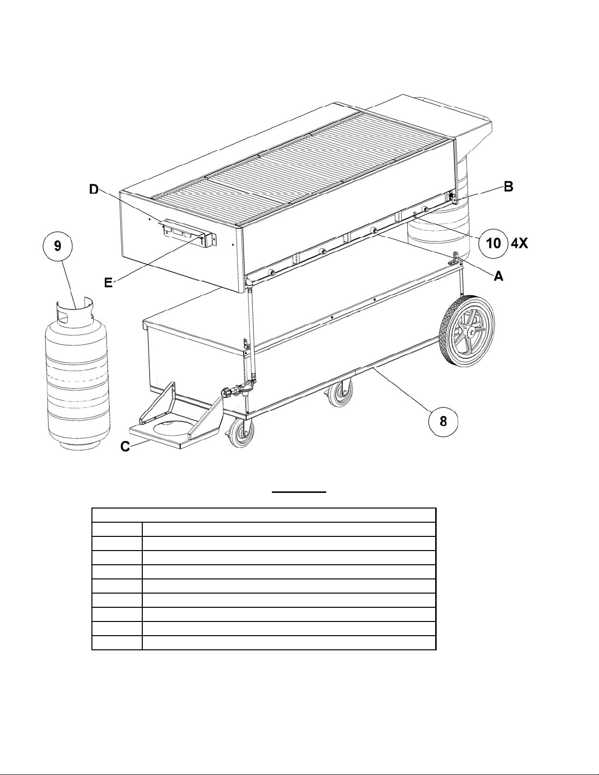
2.2. Cabinet Frame/Base Assembly
FIGURE 3
Note: Service shelf not shown in Figure 3 for clarity.
CABINETFRAME/BASEASSEMBLYLEGEND,FIGURE3
ITEM#
8
9
10
A
B
C
D
MOBILEBASE,(SHOWNWITHOPTIONALEZROLLWHEELS)
PROPANECYLINDER,40LB.VERTICAL
BOLT,1/4‐20UNCSSTHEXHEAD
CABINETFRAMESUPPORTBRACKET
1/4‐20UNCTHREADEDINSERTS
BOTTLE,BASESUPPORTBRACKET
BOTTLE,CYLINDERRETAINERBRACKET
E
A. Slide cabinet frame assembly onto the base so that the clearance holes in the cabinet frame support bracket (A) are
aligned with ¼-20 threaded inserts (B) of the cabinet frame.
B. Secure the cabinet frame to the base using the provided ¼-20 bolts, tighten the bolts to 1-2 turns past
hand tight to make sure the assembly is secure.
DESCRIPTION
WINGNUT,1/4‐20UNC
7
Page 8

C. Ensure that ¼-20 wing nuts (E) are loosened enough to allow the cylinder bracket(s) (D) to move up and down freely.
D. Place the bottom ring of the propane cylinder(s) (9) into the receiving hole of the base bottle support bracket(s) (C).
While holding the cylinder securely, insert the top ring of the cylinder (9) into the slots of the bottle retaining bracket
(D). Tighten the ¼-20 UNC wingnut(s) (E) so the bottle cylinder retaining bracket(s) are secured.
E. Connect the gas regulator assembly(s) (7) to the hose connection located at the top of the cylinder (9). The
green QCC1 connector on the hose assembly screws onto the threaded connection hand-tight.
3. INSTALLATION INSTRUCTIONS
Note: This appliance is intended to operate with an approved self contained propane cylinder with a minimum
capacity of 40 Lbs.
Units may be installed with 0” minimum clearance from sides and back to non-combustible construc tion in areas that are nonco m b us t i b l e l o c a t i on s . T h is u n i t i s not approved for installation in combustible constructions.
Important- Ensure that the gas regulator hose assembly has been properly installed prior to continuing. For built in, or fixed gas
supply appliances ensure that the provided gas regulator has been installed.
If required by local codes, the vent line from the gas appliance pressure regulator shall be inst alled to the outdoors in accordance therewith.
In the absence of local codes, the vent line shall be installed in accordance with the National Fuel Gas Code, ANSI
Z223.1/NFPA54, Natural Gas Installation Code, CAN/CGA-B149.1, or the Propane Installation Code, CAN/CGA-149.2,
as applicable.
3.1. Gas Information
The energy requirements for your appliance can be found on the data information plate located on the inner sidewall.
Orifices are sized to provide proper gas flow to the rated BTU/hr for each model. Regulator pressure must be measured
and adjusted before the unit goes into service, following installation and when operational performance is in question. The
manifold and supply pressure readings are taken at the pressure test points provided.
GASINFORMATION
GasType
Natural
Propane
BTU/Hr(kW)
perMainBurner
20,000(5.86) 25,000(7.33)
BTU/Hr(kW)
perSideBurner
ManifoldPressure
AllModels
4.0"WC(10.1cm)
10.0"WC(25.4cm)
3.2. Leak Testing
When the gas connections and installation is complete, it mu st be tested for gas leaks before use. Turn all burner control
valve(s) to the “off” position. Wet all gas line fittings and connectors with a solution of soapy water (or commercial leak
disclosing liquid). Follow the lighting instructions in Section 6 to light the runner tubes only and look for bubbles or foam at any of
the joints in the system. If a leak is found, close the main gas valve immediately and call your local dealer, the ASAP agency
or .the manufacturer.
If the gas connections are leak-free, the unit is ready to use. Continue to follow the lighting instructions in Section 5.
8
Page 9

4. APPLIANCE DIAGRAM
FIGURE 4
4.1. Operational Features
The diagram above outlines some of the key operational components of your appliance, see Figure 4.
1. Side Service Shelf
Side service shelves are fixed in place, and are standard equipment on models equipped with a mobile base.
2. Self Contained Propane Cylinder
Propane cylinders used with this appliance must be constructed and marked in accordance with the specifications for
propane cylinders of the US department of Transportation (DOT), and for specifications for LP-gas cylinders of the
National Standard of Canada, CAN/CSA-B339, cylinders, spheres, and tubes for the Transportation of Dangerous
Goods.
3. Pilot Knob, I/O (On/Off)
In the “On” position this knob will allow gas to flow to the pilot runner tubes, and the gas supply for the main burners.
Models 45 and 60 may have two (2) pilot knobs, 1 on the left and right side of the appliance.
4. Main Burner Valve, Off/On/Low
Allows gas to flow to the main burners. This should only be in the on position if the pilot runner tubes have been
ignited and flame has been verified. These knobs may also be used for the side burner valve(s) (12), see figure 5, if so
equipped.
9
Page 10

5. Water Tubs, (Drain Optional)
When used as intended with water, the water tubs reduce grease flare up, and make cleanup easier.
6. Pilot Runner Tube Spark Ignitor
Battery operated spark system that ignites the pilot runner tube.
7. Side Burner Spark Ignitor, (If Equipped)
Battery operated spark system that ignites both the front and rear side burners individually.
8. Stainless Steel Cooking Grate(s)
Commonly referred to as top grids, these are provided as standard parts with the appliance.
9. Chrome Plated Griddle, (Optional Equipment)
To use the griddle plate option, replace one (1) cooking grate where desired.
CAUTION:
Never try to remove a hot griddle or cooking grate, always allow the cooking surface to cool to room
temperature. Failure to do so cause result in severe personal injury, or death.
10. Front and Rear Side Burner(s), (Optional Equipment)
May not be available in certain locations on the appliance.
5. BASIC OPERATION
Fill water tubs to within ½” of top edges
(this will control grease flare-ups,
provide for ease of cleaning and keep
cooked foods moist). Re-fill tubs with
water when they evaporate to within ½”
of the bottom of the tubs. Failure to
keep water in the water tubs wil l lead to
grease fires and will void the warranty.
5.1. Main Burner Lighting Instructions DIAGRAM 1
Prior to lighting the unit, make sure all gas valve knobs are in the “Off” (0) position, proceed when all gas valves are
closed. If your appliance is equipped with a hood, make sure the hood is in the raised open position. It is extremely
important that the main burners are properly installed in the appliance and the main burner orifices are properly mounted
and aligned with respect to the main burners. The main burners should be secured properly on each end, and the main
burner orifice installed into the burner correctly, see diagram 1. The orifice should be perfectly centered and pointing
straight into the burner tube. Improperly installed orifice tips or main burners may cause poor performance or an unsafe
condition. If you have any questions concerning the burner or orifice installation, contact a qualified service company, or
the MagiKitch’n factory for further assistance.
A. Open the gas supply valve on the propane cylinder (2). Turn the pilot gas valve (3) to the “On” (I) position. Depress the
runner tube spark igniter button (6) until the pilot runner tube is lit, you should hear a prominent “clicking” sound.
Note: If there is no clicking sound emitting from the spark Ignitor it may be an indication that there is no battery in
the unit, or the battery has no charge.
B. Verify that the pilot runner tube has ignited with flame by looking through the sight hole (11). This hole can also be
used to light the runner tube with a lit match or grill lighter. Check that the entire runner tube is lit. If the runner tube(s)
will not light or stay lit, shut off the gas supply and do not use the unit. Wait 5 minutes before attempting to re-light the unit.
C. Once flame is verified at the pilot runner tube, open the desired main burner valve (4) to the “On” (I) position and
verify that the burner lights prior to lighting the next burner. Each runner tube will light up to four (4) main burners.
After each burner is lit, the control knob can be changed from Hi to Low as desired, see diagram 2.
Warning
If the runner tube(s) or burners fail to light or remain lit, sh ut off the gas supply and discontinue use of the unit. Call a
qualified service company to correct the problem.
10
Page 11

5.2. Optional Side Burner Lighting Instructions
Prior to lighting the unit, make sure all gas valve knobs are in
the “Off” position, proceed when all gas valves are closed. If
your appliance is equipped with a hood, make sure the hood is
in the raised open position. Refer to figure 5 for the following
steps unless otherwise instructed.
A. Open the gas supply valve on the propane cylinder (2).
B. Turn the pilot gas valve (3) to the “On” (I) position.
DIAGRAM 2
C. Turn the desired side burner valve (12) to the “On” (I) position. There will be a circled flame that denotes which valve
controls the front or rear side burner.
Note: If the appliance is not equipped with an optional side burner, then the side burner valve(s) (12) will be
additional main burner valve(s) (4).
D. Depress the stove igniter button (7) until the desired side burner is lit, you should hear a “clicking” sound emitting from
the spark igniter.
Note: If there is no clicking sound emitting from the spark igniter it may be an indication that there is no battery in
the unit, or the battery has no charge.
D. Verify that the desired side burner (10), See figure 4, is lit. Flame will be visibly emitting from around the entire
circumference of the burner if operating properly. If t h e s i d e b u r n er(s ) w i l l not l i ght o r s t ay li t , s h u t off the ga s supply and do
not use the unit. Wait 5 minutes before attempting to re-light the unit. After each side burner is lit, the control knob can be
changed from Hi to Low as desired, see diagram 1.
FIGURE 5
5.3. Shutdown Instructions
To safely shutdown the appliance, perform the following steps in the order shown:
A. Turn all the main burner valve(s) (4), or side burner valve(s) (12) to the “Off” (0) position.
B. Turn off the pilot valve(s) (3) to the “Off” (0) position.
C. Close the valve on the approved propane cylinder (2). See Figure 5.
11
Page 12

5.4. Cleaning the Unit
The appliance should be cleaned after each use to maintain proper function and appearance. The build up of grease and other
debris can cause improper operation, or an appliance malfunction.
Allow the appliance to cool to room temperature prior to performing any of the following cleaning procedur es . It is als o
recommended to wear eye protection, and oil resistant gloves while cleaning this appliance.
Prior to performing and service, cleaning or daily maintenance to the appliance turn off and disconnect the gas supply and
any electrical power supplies, if so equipped.
Cooking Top Grid:
A. If available, use an approved grill brush to clean off any loose debris from the cooking grate. The debris will fall into the
water tubs below the radiant(s)
B. Remove the grate(s) from the unit and use warm soapy water top clean the remainder of the grease and debris from the
grate. It is recommended to use a stiff bristled brush or plastic pad in the cleaning process, do not use steel wool or
abrasive pads as they may degrade the metal finish.
C. Rinse the cooking grate thoroughly with cool water to remove any remaining soap residue from the surface.
CAUTION:
Never try to remove any parts from the appliance while it is hot, always allow the appliance to cool to room
temperature. Failure to do so cause result in severe personal injury, or death.
Burner Radiant(s): (These will need little or no cleaning due to high in-use temperatures)
A. Remove the radiant(s) from the radiant support pins.
B. Use a cleaning pad to wipe any debris from all surfaces.
C. Install radiant(s) onto the radiant support pins.
Internal Cabinet Frame Walls:
A. Remove cooking grate(s), radiant(s), and Pilot runner tube cover(s).
B. Apply warm so a p y water with a stiff bristle brush or plastic pad to the interior surfaces of the cabinet
frame. Be careful not to get water into the main burners or pilot runner tubes. Do not pressure wash.
C. Rinse the surfaces with cool water to remove any remaining soap residue and wipe dry with a lint free cloth.
D. Replace any removed parts back to their normal operating position.
External Cabinet and Base Surfaces:
The exterior surfaces are made from polished stainless steel.
A. Using a lint free soft cloth or towel, clean all surfaces with an approved stainless steel cleaner.
B. With a clean towel or cloth, wipe any excess cleaning agents from the surface.
Water Tubs:
A. Drain water from tub into a grease resistant container if equipped with optional drain. If no drain
available, carefully remove the water tub(s) from the appliance and drain the water into a grease
resistant container.
B. Use warm soapy water applied with a stiff bristle brush or plastic cleaning pad to clean all internal and
external surfaces of the water tub(s).
C. Rinse with cool water and wipe dry with a soft lint free towel or cloth.
D. Return the water tub(s) to their normal operating position.
5.5. Rotisserie Operation
Some appliances may be equipped with an optional rotisserie, following are some tips for basic operation and guidelines
to operate the rotisserie properly.
The rotisserie is available in 30” sizes only, and can be mounted from the left or right side of the appliance. Only one (1)
rotisserie may be installed per appliance.
The maximum weight intended for use on the rotisserie is 25 Lbs., any loads greater than 25 Lbs. may cause the appliance
to perform inadequately, or cause motor failure.
12
Page 13

To assemble the rotisserie refer to the following steps, refer to figure 6 unless otherwise instructed.
FIGURE 6
The rotisserie motor housing assembly (13), shown on the left, is fixed to the side shelf with hex head bolts. It can be
removed with the use of simple tools for storage. The rotisserie is shown assembled in figure 6, the legend below
identifies the parts for reference.
ROTISSERIEASSEMBLYLEGEND,FIGURE6
ITEM#
8
9
13
14
15
16
17
18
19
20
STAINLESSSTEELCOOKINGGRATE
ROTISSERIEMOTORHOUSINGASSEMBLY
QUICKRELEASERETENTIONPIN
WARMINGRACKSUPPORTBRACKETS(RACKNOTSHOWN)
DESCRIPTION
CHROMEPLATEDGRIDDLE
SPITCOUPLING
ROTISSERIESPIT
ROTISSERIEFORKS(2)
ON/OFFSWITCH
POWERCORD
A. The spit coupling (14) secures the rotisserie spit (16) to the motor housing assembly (13).
B. The quick release pin (15) is used to connect and disconnect the spit from the motor. To connect, align the holes in
the end of the spit (16) with mating holes in the spit coupling (14).
C. The spit (16) needs to be disconnected to place food product for cooking. The rotisserie forks (17) are placed onto the
spit after the food product has been placed.
13
Page 14

D.
Insert the pointed end of the spit (16) through the food product, then slide a rotisserie fork (17) on either side of the
food product with the forks pointing toward the food. Insert the forks into to the food, and secure the fork(s) (17) to
the spit (16) so the food product is located over the center of the cooking area. Use the knobs on the fork(s) (17) to
secure the product to the spit (16). For best results, use the flat surface on the spit (16) to secure the fork(s) (17) to.
E. Prior to connecting the loaded spit to the coupling, wipe any food debris from the pointed end of the spit (16), and
where the spit will be resting in the bushings of the hood. Place the loaded spit into the bushings and manually spin
the spit to ensure that the food product will not interfere with the cooking grates, or any part of the hood assembly.
F. Connect the spit (16) to the spit coupling (14) as described in step B.
G. Use a grounded extension cord rated for outdoor use to connect the rotisserie power cord (19) to a 120V 60hZ power
supply.
H. To start the rotisserie, put the rotisserie switch (18) to the (I) “On” position.
5.6. Griddle Operation
The chrome griddle plate (9) is used in place of a cooking grate (8), To use the griddle just remove one of the grates and
replace with the chrome griddle (9) in the vacated position in the appliance.
CAUTION:
Never try to remove any parts from the appliance while it is hot, always allow the appliance to cool to room
temperature. Failure to do so cause result in severe personal injury, or death.
WARNING:
Never operate the appliance with out a cooking grate, or griddle in place. Failure to do so cause result in severe
personal injury, or death.
6. OPTIONS AND ACCESSORIES
Rotisserie — Available in 30” sizes only, must be ordered with a hood opti on.
Chrome plated griddle — Heavy polished steel griddle for cooking breakfasts, sautéing, etc.
Steamer Set — Holds full-size hotel pans for steaming and warming.
Cutting Board —Full length custom fitted cutting board fits over the service shelf.
Hood(s) — Single or dual hood keeps heat in for roasting and broiling.
Windguard — Keeps grill firing properly in windy conditions.
Warming Rack- Adjustable and removable as needed, must be ordered with hood or windguard.
Vinyl cover — Durable custom fit cover that protects against dirt and weather dama ge.
7. WARRANTY
MagiKitch’n appliances are designed to give you long and satisfactory service if installed and operated in accordance with
our instructions. This appliance has been carefully tested, but there may be a defect not imme diately noticeable. To protect
you, we warrant this appliance against defective workmanship and material for 1 year from the date of shipment..
7.1. Not Warranted
Accident to, misuse of, harsh chemical cleaners, or natural wear of this appliance.
7.2. Important Service Information
All maintenance and /or repairs to this appliance should be performed by an Authorized Service Professional. Please
contact the factory representative, or the factory directly to locate the Authorized Service and Parts(ASAP) agency in your
area.
Any defective parts must be returned for replacement under this warranty.
When calling or writing, be sure to mention the serial number and model number appearing on the nameplate on the front
of your equipment. Write the model, serial number and the installation date in the information box on the front of this
manual where it will always be handy when you need it.
14
Page 15

15
Page 16

509 Route 3A
Bow, NH 03304
PHONE- (603) 225-6684
FAX- (603) 225-8472
WWW.MAGIKITCHN.COM
L25-057 Rev. 0 (10/13)
16
 Loading...