

Page 1
IMPORTANT FOR FUTURE REFERENCE
Please complete this information and retain this manual
for the life of the equipment:
Model #: ___________________________
Serial #: ___________________________
Date Purchased: ____________________
ENGLISH
Technical Service Manual
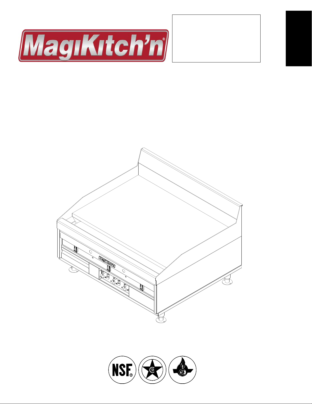
Models
MKG/MKH/MKGD
24,36,48,60 & 72
All Options
Solid State Thermostat Model Shown
S
I
E
G
D
N
D
C
E
E
I
R
F
T
I
CIRET IFED
L22-362 Rev 2 (11/12)
Page 2

Technical Service Manual
MKG/MKH/MKGD Series Gas Griddles
WARNING
DO NOT store or use gasoline or other flammable
vapors and liquids in the vicinity of this or any other
appliance.
WARNING
Improper installation, alteration, service or maintenance
can cause property damage, injury or death. Read the
installation, operating and maintenance instructions
thoroughly before installing or servicing this appliance.
WARNING
Installation, maintenance and repairs should be
performed by a MagiKitch’n Authorized Service and
Parts (ASAP) company technician or other qualified
personnel. Installation, maintenance or repairs by an
unauthorized and unqualified personnel will void the
warranty.
WARNING
Installation and all connections must be made according
to national and local regulations and codes in force.
WARNING
During the warranty period if a customer elects to use a
non-original part or modifies an original part purchased
from MagiKitch’n and/or its Authorized Service and
Parts (ASAP) companies, this warranty will be void. In
addition, MagiKitch’n and its affiliates will not be liable
for any claims, damages or expenses incurred by the
customer which arises directly or indirectly, in whole or
in part, due to the installation of any modified part
and/or received from an unauthorized service center.
WARNING
This appliance, when installed, must be electrically
grounded in accordance with local codes, or i n the
absence of local codes, with the National Electrical
Code, ANSI/NFPA 70, or the Canadian Electrical Code,
CSA C22.2, as applicable.
WARNING
Adequate means must be provided to LIMIT the
movement or this appliance without depending on the
gas or electrical cord connection. Single appliances
equipped with legs must be stabilized by installing
anchor straps. All appliances equipped with casters
must be stabilized by installing restraining chains.
WARNING
An appliance equipped with casters and a flexible gas line must be
connected to the gas supply with a quick disconnect device. This
quick disconnect must comply with ANSI Z24.41.
WARNING
DO NOT alter or remove structural material on the
appliance to accommodate placement under a
ventilation hood.
WARNING
This appliance is intended for professional use only and
should be operated by fully trained and qualified
personnel.
WARNING
If the appliance is equipped with a power cord and it is
damaged, it must be replaced by a MagiKitch’n
Authorized Service and Parts (ASAP) company
technician, or a similarly qualified person in order to
avoid a hazard.
WARNING
The power supply must be disconnected before
servicing, maintaining or cleaning this appliance.
WARNING
The appliance is NOT jet stream approved. DO NOT
clean the appliance with a water jet.
WARNING
DO NOT attempt to move this appliance or transfer hot
liquids from grease box to another container when the
unit is at operating temperature or filled with hot liquids.
Serious personal injury could result if skin comes in
contact with the hot surfaces or liquids.
WARNING
DO NOT sit or stand on this appliance. The appliance’s
front panel, cook plate, splash back, sides, workshelf is
not a step. Serious injury could result from slipping,
falling or contact with hot surfaces or hot liquids.
WARNING
NEVER use the appliance as a step for cleaning or
accessing the ventilation hood. Serious injury could
result from slips, trips or from contacting hot surfaces
or liquids.
WARNING
This appliance is intended for indoor use only.
WARNING
DO NOT operate appliance unless all panels and access
covers are attached correctly.
WARNING
It is recommended that this appliance be inspected by a
qualified service technician for proper performance and
operation on a yearly basis.
WARNING
There is an open flame inside this appliance. The unit
may get hot enough to set nearby materials on fire.
Keep the area around the appliance free from
combustibles.
WARNING
DO NOT supply the appliance with a gas that is not
indicated on the data plate. If you need to convert the
appliance to another type of fuel, contact your
equipment dealer or a MagiKitch’n Authorized Service
and Parts (ASAP) Company.
WARNING
DO NOT use an open flame to check for gas leaks!
WARNING
If gas flow to appliance is interrupted, or pilots
extinguish, wait 5 minutes before attempting to relight
the pilot to allow any residual gas in appliance to
dissipate.
WARNING
Ensure that the appliance can get enough air to keep the
flame burning correctly. If the flame is starved for air, it
can give off a dangerous carbon monoxide gas. Carbon
monoxide is a clear odorless gas that can cause
suffocation.
Page 2 L22-362 Rev 2 (11/12)
Page 3

Technical Service Manual
MKG/MKH/MKGD Series Gas Griddles
TABLE OF CONTENTS
OVERVIEW ................................................................................................................................... 4
1.1 INTRODUCTION.................................................................................................................................. 4
1.2 S
2 THEORY OF OPERATION .................................................................................................... 5
2.1 HEATING SYSTEM –SNAP ACTION SERIES .......................................................................................... 5
2.2 H
2.3 TEMPERATURE CONTROL SYSTEMS ................................................................................................... 6
3 TEMPERATURE CALIBRATION .......................................................................................... 6
3.1 TEMPERATURE MEASUREMENT: .......................................................................................................... 6
3.2 CALIBRATION PROCEDURES: .............................................................................................................. 7
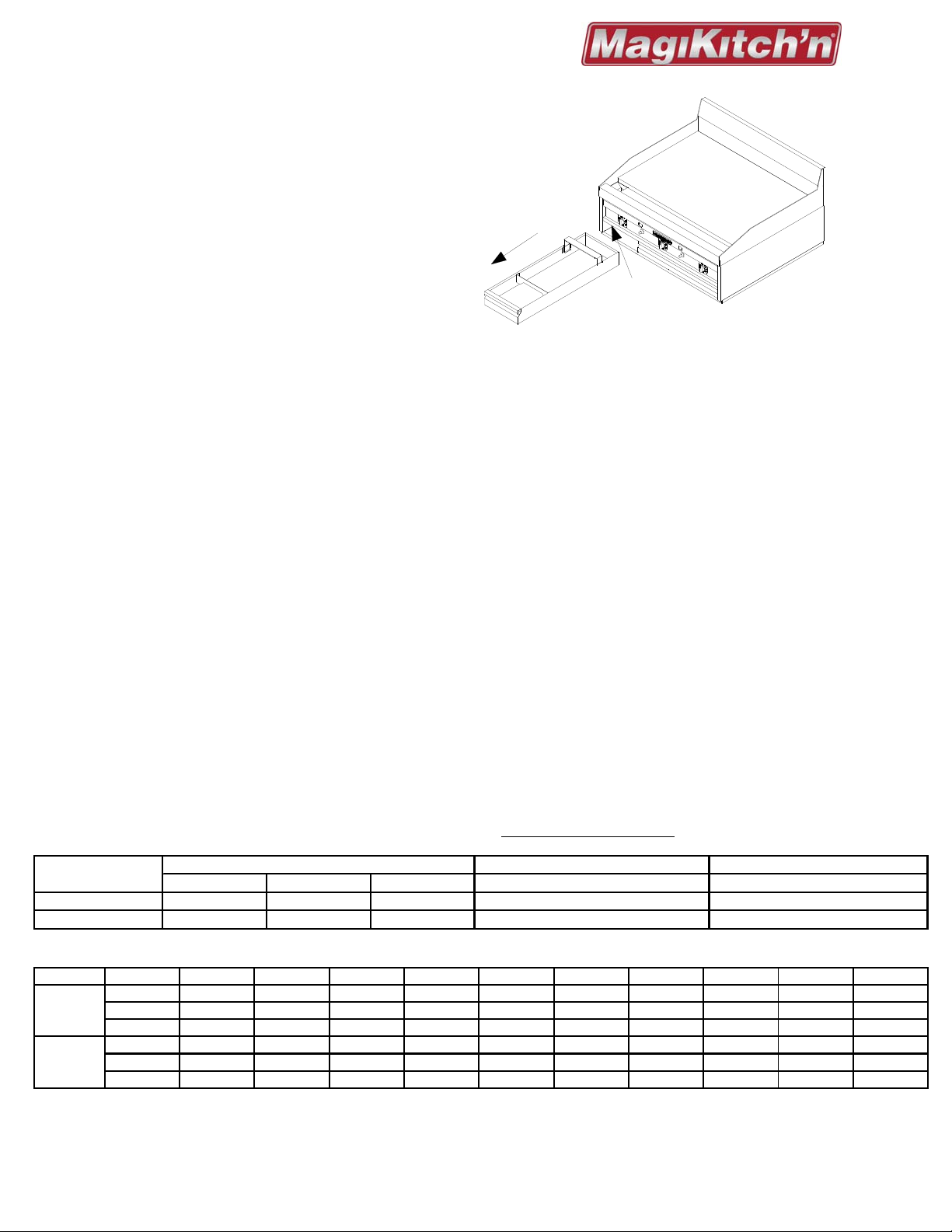
4 COMPONENT CHECK & REPLACEMENT .......................................................................... 8
4.1 DISASSEMBLY OF FRONT PANELS ...................................................................................................... 8
4.2 PILOT / IGNITION SYSTEM CHECK ....................................................................................................... 9
4.3 IGNITION MODULE REPLACEMENT .................................................................................................... 12
4.4 PILOT ASSEMBLY REPLACEMENT ..................................................................................................... 12
4.5 B
4.6 ORIFICE/FUEL TYPE CONVERSION ................................................................................................... 13
4.7 MAIN BURNER REPLACEMENT ......................................................................................................... 13
4.8 GAS PRESSURE ADJUSTMENT ......................................................................................................... 14
4.9 TEMPERATURE CONTROLS CHECK ................................................................................................... 15
4.10 TEMPERATURE CONTROL REPLACEMENT .......................................................................................... 17
4.11 SAFETY VALVE REPLACEMENT ........................................................................................................ 19
4.12 SOLENOID VALVE REPLACEMENT- .................................................................................................... 19
4.13 POWER SUPPLY TRANSFORMER MATCHLESS MODELS “E” & “ST” ..................................................... 21
4.14 SWITCH AND LAMP REPLACEMENT ................................................................................................... 22
PECIFICATIONS ............................................................................................................................... 4
1.2.1 Gas Information ...................................................................................................................................... 4
1.2.2 Elevation Orifice Chart ........................................................................................................................... 4
EATING SYSTEM –MATCHLESS IGNITION SERIES (E / ST) .................................................................. 5
3.2.1 Snap Action and Matchless (E) Series ................................................................................................... 7
3.2.2 Matchless (ST) Series ............................................................................................................................ 7
4.1.1 Snap Action Series ................................................................................................................................. 8
4.1.2 Matchless Series (E & ST) ..................................................................................................................... 8
4.2.1 Ignitor Check- Snap Action Series .......................................................................................................... 9
4.2.2 Spark Failure- Matchless (E & ST) Series ............................................................................................ 10
4.2.3 Insufficient or Absence of Flame: ......................................................................................................... 11
4.2.4 Pilot Lock-in: Snap Action Series ......................................................................................................... 11
4.2.5 Pilot Lock-in- Matchless Series (E & ST) .............................................................................................. 12
URNER ADJUSTMENTS .................................................................................................................. 12
4.6.1 Changing Burner Orifice ....................................................................................................................... 13
4.9.1 Snap-Action Models ............................................................................................................................. 15
4.9.2 Matchless “E” Models ........................................................................................................................... 15
4.9.3 Matchless “ST” Models ......................................................................................................................... 16
4.9.4 Temperature Probe Check: .................................................................................................................. 16
4.9.5 Resistance Chart: Solid State Thermistor Probe .................................................................................. 17
4.10.1 Snap Action Models ............................................................................................................................. 17
4.10.2 Matchless “E” Models ........................................................................................................................... 17
4.10.3 Matchless “ST” Models ......................................................................................................................... 18
4.10.4 Thermistor Probe Replacement............................................................................................................ 18
4.12.1 Pilot Solenoid Valve ............................................................................................................................. 19
4.12.2 Main Burner Solenoid Valve ................................................................................................................. 20
4.13.1 Power Supply Transformer Check ........................................................................................................ 21
4.13.2 Power Supply Transformer Replacement ............................................................................................. 21
5 TROUBLESHOOTING GUIDE ............................................................................................. 23
5.1 TROUBLESHOOT GUIDE -SNAP ACTION MODELS ............................................................................... 23
5.2 T
5.3 SCHEMATIC: MATCHLESS “E” SERIES ............................................................................................... 25
5.4 S
5.5 S
5.6 SCHEMATIC: MATCHLESS SINGLE POWER SWITCH “ST” SERIES ........................................................ 28
L22-362 Rev 2 (11/12) Page 3
ROUBLESHOOT GUIDE - E / ST SERIES ........................................................................................... 24
CHEMATIC: MATCHLESS “ST” SERIES ............................................................................................ 26
CHEMATIC: MATCHLESS SINGLE POWER SWITCH “E” SERIES .......................................................... 27
Page 4
Technical Service Manual
A
A
r
MKG/MKH/MKGD Series Gas Griddles
1 Overview
1.1 INTRODUCTION
All models
All models are equipped with pilot safety
system, spark enabled pilots, temperature
controls for each 12” zone, heated by two
burners. Temperature sensing probes are
embedded into the plate between each pair of
burners.
MKG/MKH/MKGD Series appliances may
have suffixes that denote the following:
Numerals 24, 36, 48, 60, and 72 denote the
width of the appliance in inches.
Suffix “L”, “R” and “B” denote left, right and rear grease troughs, respectively.
Important information located on Data Plate, See Figure 1 at right.
Snap Action Models
Snap Action models have gas safety valves, Piezo pilot ignition systems and snap action gas
temperature controls.
Snap Action models have no suffix designation.
Snap Action models require no external electrical supply.
Matchless Models
Letter designations represent matchless ignition (flame proving spark ignition), temperature control
options and grease chute options.
Suffix “E” models have flame proving spark ignition systems and electro-mechanical thermostats.
External power supply is required.
Suffix “ST” models have flame proving spark ignition systems with solid state temperature controls.
External power supply required.
Matchless models have 120 Vac 60HZ electrical supply, and 24 Vac control circuitry.
Installation, Operation and Cleaning
A qualified person, in accordance with all national and local codes, must perform the installation.
Detailed instructions are in the INSTALLATION & OPERATION manual supplied with the appliance.
1.2 SPECIFICATIONS
1.2.1 Gas Information
Gas supply line must be ¾ “ minimum, providing line pressures at least 1.0” (25mm) greater
than the specified griddle manifold pressure with all burners operating
Gas Type
Natural 15,000 (4.4) 13,333 (3.9) 18,000 (5.3) 4.0" WC (10.1cm) [10 mbar] 5.0" WC (12.7cm) [12.5 mbar]
Propane 15,000 (4.4) 13,333 (3.9) 18,000 (5.3) 10.0" WC (25.4cm) [25 mbar] 11.0" WC (27.9cm) [27.4 mbar]
1.2.2
Gas Type Model Sea level 2000 Ft. 3000 Ft. 4000 Ft. 5000 Ft. 6000 Ft. 7000Ft. 8000 Ft. 9000 Ft. 10,000 Ft,
Natural
MKGD
Propane
MKGD
Elevation Orifice Chart
MKG
MKH
MKG
MKH
BTU/hr(kW) per Burne
MKG MKH
49 50 50 50 51 51 51 52 52 52
0.066"0.066"5152525253535354
45 46 47 47 47 48 48 49 49 50
1.15mm 1.15mm 1.15mm 57 57 57 58 59 59 60
57 58 59 59 60 60 61 62 63 63
1.25mm 1.25mm 1.25mm 57 57 57 58 59 59 60
MKGD
Electrical Information
Snap Action models require no electrical supply. All Matchless Series (-E and -ST) require 115v/60hz/1ph
electrical supply. The appliance is fitted with a grounded 15-amp cord and plug (NEMA 515-P).
REMOVE
GREASE BOX
DATA PLATE
ON INSIDE WALL
.
Manifold Pressure Nominal Supply Pressure
ll Models
ll Models
Page 4 L22-362 Rev 2 (11/12)
Page 5
Technical Service Manual
MKG/MKH/MKGD Series Gas Griddles
2 Theory Of Operation
This section will demonstrate the basic sequence of
operation for Snap Action and Matchless (E/ST)
Ignition series.
2.1 HEATING SYSTEM –SNAP ACTION
SERIES
Pilots are lit by, (See Photo 1):
- Opening the shut off valve (C)
- Depressing the Piezo spark buttons (A)
while depressing and holding the button on
the safety valve (B) to ignite flame at pilot.
- Once ignited, keep button (B) depressed
for 20 seconds to lock in the safety valve.
2.2 HEATING SYSTEM –MATCHLESS
IGNITION SERIES (E / ST)
Start up of Unit, (See Photo(s) 2, and 2a):
- Open the shut off valve (C)
- Pres s Rocker Switch (A), to ON (I) for
each 12” zone to ignite pilots.
- Set thermostat controls (B) to set point
When the appliance is plugged in, line voltage
is supplied to an 80 VA transformer located in
the power supply boxes located in the rear of
the unit. The transformer then supplies 24
VAC to the rocker switches for the control
circuitry, the switches are located on the
control panel, centered on each 12” zone.
The rocker switches (A) are double pole (DP).
Photo 1
Once safety valve is locked in, the "snap acting”
gas thermostats supply gas to their respective
burners upon “call for heat “.
The thermostats cycle gas to the
burners to maintain cooking surface
temperatures at set point.
On snap action models the burner operating
pressure is measured at the pressure tap on
the shut off valve (C), and controlled by the gas
regulator (D), mounted in the back of the unit,
See Photo 1a.
Photo 2
One set of contacts supplies power to the
ignition modules (and to the Solid State
temperature control boards on -“ST” Series).
The second set of contacts switches power
from the thermostat control (B), to the main
gas valve solenoids allowing gas to the main
burners.
The ignition modules supply spark energy to
the ignitor electrodes and power to the pilot
gas valve solenoids to establish pilot flames.
The modules also rectify pilot flame by means
of integral flame sense (spark and flame sense
supplied through the ignition wire).
Photo 1a
Photo 2a
L22-362 Rev 2 (11/12) Page 5
Page 6
Technical Service Manual
MKG/MKH/MKGD Series Gas Griddles
Photo 2b
Once pilots ignite, the ignition modules will
send power to the burner valves, traveling first
through the thermostat control, then through the
second contacts of the rocker swit ches.
The Solid State temperature controls or the
Electric thermostats, cycle the power to
maintain set temperature.
Supply line gas pressure on matchless models
is measured at the pressure tap on the shut off
valve (C), mounted in the back of the unit,
accessible from the back of the appliance only,
See Photo 2a.
Matchless models the burner operating
pressure is measured at the pressure tap (E)
on the burner supply line, and controlled by the
gas regulator (D), See Photo(s) 2a.(rear view)
and 2b (front view). The Pressure tap and
regulator adjustment are front accessible with
the lower panel removed, see section 4.
2.3 TEMPERATURE CONTROL SYSTEMS
Snap action appliances have bulb and capillary
style “Gas Operated” thermostats. The
thermostat has a temperature range of 200° to
450°F, See Photo 3.
Electric thermostat (-E) models have a bulb and
capillary style “Electro-mechanical Operated”
thermostats. The thermostat has a temperature
control range of 200° to 550°F, See photo 4.
Photo 3
Photo 4
Photo 5
The Solid State (-ST) model has temperature
control system consisting of a solid state
board, and a Thermistor probe. The sensing
probe is connected to the control board via
“push-on” terminals. The control has a
temperature range of 150° to 550°F, See
Photo 5.
Notice:
Matchless Ignition (E/ST) models have flame
proving park ignition systems. An external power
supply is required on these models.
Notice:
The sensing bulbs or Thermistor probes for each
of the controls are embedded in a slot on the
underside of the cooking surface. The Snap-Action
and Electric thermostat bulbs are “pressed” into
the slot. The Thermistor probe is “inserted” into a
hole at the end of the slot.
3 Temperature Calibration
Each temperature control operates a twelve- (12)
inch zone. Each zone consists of two burners
(except for zones containing a left or right grease
chute/trough). There are three different control
options as noted in Section 2.3. The controls are
factory set. However, if the cooking surface
temperature varies greatly from the setting on the
thermostat knob, adjust the thermostat using the
following procedure:
3.1 TEMPERATURE MEASUREMENT:
Using a calibrated instrument with a surface probe,
measure the temperature in the center of each
zone, 12” in from the front edge of the cooking
surface. The zone centers are located side to side
by the following: (1) Matchless ignition I/O
switches, (2) Snap-Action thermostat knobs, or (3)
Arrows located on the griddle front top rail. The
zone should run at set temperature for at least 30
minutes to allow the zone to stabilize prior to the
calibration check. The temperature will vary with
burner cycling but should stay within +/- 15° F of
the knob setting. The thermostat knob should
indicate the average temperature of the
corresponding zone. If adjustment is required,
follow the instructions in Section 3.2 for the control
type in use.
Page 6 L22-362 Rev 2 (11/12)
Page 7
Technical Service Manual
MKG/MKH/MKGD Series Gas Griddles
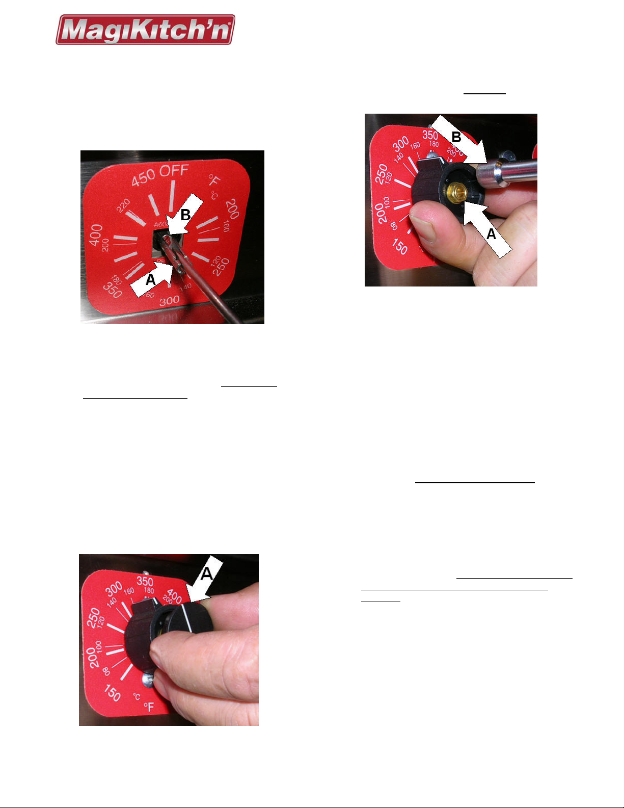
3.2 CALIBRATION PROCEDURES:
3.2.1 Snap Action and Matchless (E) Series
Light pilots as described in section 2.1.
Set thermostat knobs to the desired
Photo 6
temperature and allow cooking surface to
stabilize for 30 minutes (1 hour if cold).
Remove the knob to expose the screw in the
center of the thermostat shaft. Do not allow
thermostat shaft to turn. For snap action
thermostat knobs refer to section 4.1.1. For
electric thermostat (E Series), remove knob by
pulling straight off thermostat shaft.
Remove any sealant over the head of the screw
with the tip of your screw driver.
Tightly hold the thermostat shaft (A) and turn
the adjustment screw (B) in small increments to
shift temperature (1/4 turn is approximately
30°F.). To increase temperature, turn the screw
counter-clockwise, or to reduce temperature
turn screw clockwise.
Snap Action thermostat, See photo 6.
Photo 7
Electric thermostat, (E Series), use same
sequence as Snap Action thermostat. Electric
thermostat appliances DO NOT
have a
temperature indicator label.
Photo 8
Check temperature after 15 minutes. Repeat
procedure until all zones are maintaining the
correct temperature.
3.2.2 Matchless (ST) Series
Turn on all power switches.
Set knobs to the desired temperature.
Allow appliance to stabilize for 30 minutes (1
hour if cold).
Carefully remove knob cap (A), See Photo 7.
Hold knob firmly in place and loosen the 5/16”
retaining nut (A) with an appropriate socket or
nut driver (B), See Photo 8.
NOTE: Do not remove the knob.
Once the retaining nut is loose, pull straight
out on the knob to insure that the knob can
move freely on the shaft.
Align the white indicator line with the average
temperature of the corresponding cooking
zone.
Hold knob firmly on shaft, while retightening
the retaining nut (A), do not allow knob or shaft
to move or temperature setting will not be
accurate.
Replace knob cap as seen in Photo 7, the
white indicator lines on the cap and knob
should line up with each other.
NOTE:
Diagrams or photos may have some parts or
details removed for clarity. Actual appliances
may appear differently.
L22-362 Rev 2 (11/12) Page 7
Page 8
Technical Service Manual
MKG/MKH/MKGD Series Gas Griddles
4 Component Check & Replacement
With the exception of calibration, appliance control
checks or replacement May
control cover front panels. The front panels are
removed as follows:
require removal of the
Photo 9
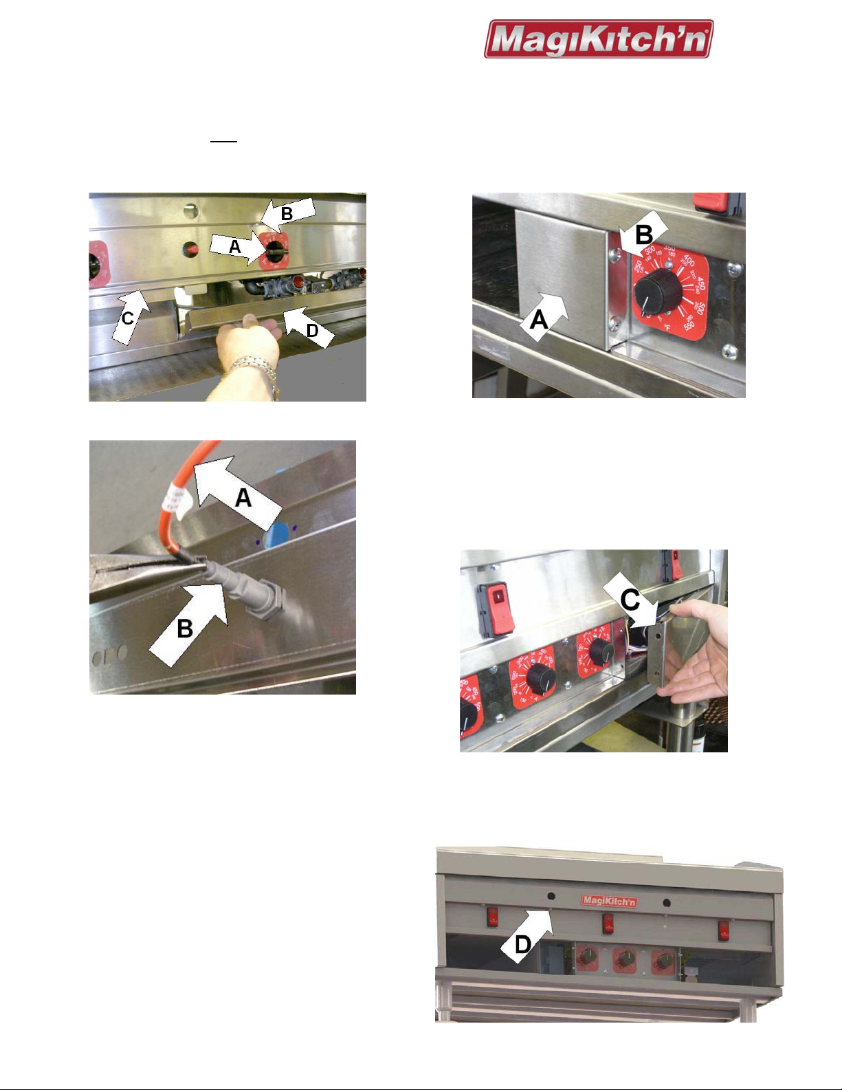
4.1.2 Matchless Series (E & ST)
To remove the left lower panel (A), remove the
grease box from the appliance. Then remove
two (2) 10-24 truss head screws (B) from the
inner flange, See Photo 11.
Photo 11
To remove the right lower panel (C), remove
the two (2) 10-24 truss head screws (B) that
secure it to the inner flange. With the
mounting screws removed, the left and right
lower panels swing away from the appliance
and will release from the retaining clips, See
Photo 12.
Photo 10
4.1 DISASSEMBLY OF FRONT PANELS
4.1.1 Snap Action Series
Remove all thermostat knobs by loosening the
shaft retaining (set) screws (A), located in the
bottom of the knob, See Photo 9.
Remove all #10 self threading screws (B),
With the lower panels removed from the
appliance you will have access to the gas
valves, ignition modules, and temperature
controls.
Photo 12
holding the upper control panel (C) in place.
Lower door panel(D) rotates down to allow
access to gas train components.
Slowly pull front panel away from front of
appliance and place in a safe location. Be
careful not damage the Piezo ignition wire as it
will still be attached at this step.
See Photo 10, Using needle nose pliers,
carefully disconnect the Piezo ignition wire(A),
from the Piezo ignitor assembly(B). The upper
panel is now disassembled from the appliance.
Photo 12a
Page 8 L22-362 Rev 2 (11/12)
Page 9
Technical Service Manual
MKG/MKH/MKGD Series Gas Griddles
To remove the upper switch panel, remove the
#10 self threading screws,(D in Photo 12a),
similar to those of the snap action panel. This
will give access to the burner manifolds.
Verify both terminal connections of the ignition
wire, (A, in Photo 10), and check the wire for
visible damage and electrical continuity.
Note: Front panel must be “grounded” to the
appliance to establish sufficient spark
Check to ensure that the Piezo ignitor, (B, in
Photo 10). is tightly mounted to the panel. A
loose connection may create an open
“ground”.
Inspect the electrode(B), and the ceramic
insulator(E) for visible damage, See Photo 14.
Verify the spark gap between the electrode(B),
and the pilot hood(A), nominal gap is .090”.
Photo 12b
The panel will be loose, but there will wire
harness connections that may need to be
disconnected to put the panel aside for further
service, the 9 position plug(s) connect the
switch panel to the gas valve assemblies, and
the 6 position plug(s) connect the switch panel
to the thermostat controls, See Photo 12b.
Important!
Carefully support switch panels so wiring
connections will not be strained. Failure to
comply may cause wiring damage.
Remove the temperature control mounting
panel by removing the four (4) 10-24 truss head
screws, see photo 13.
Photo 14
If all parts are in good condition, check for
sufficient spark by first removing the ignition
wire,(C) from the electrode terminal.
Hold the “open” terminal of the ignition wire
1/8” from front panel with insulated pliers, and
depress the red button of the Piezo ignitor.
Check for a visible spark to the panel, See
Photo 15.
If no spark is produced, replacement of the
Piezo ignitor may be required.
Photo 13
To replace the piezo igniter, remove the
ignition wire from the igniter and set aside.
Remove the igniter from the panel by
Disconnect all wiring harness’ and place both
loosening the igniter retaining nut.
the switch panel, and the control panel in a safe
location so they will not become damaged.
Once the panels have been disassembled from
the unit, there will be access to the gas valves,
pilots, fuse(s), and ignition modules.
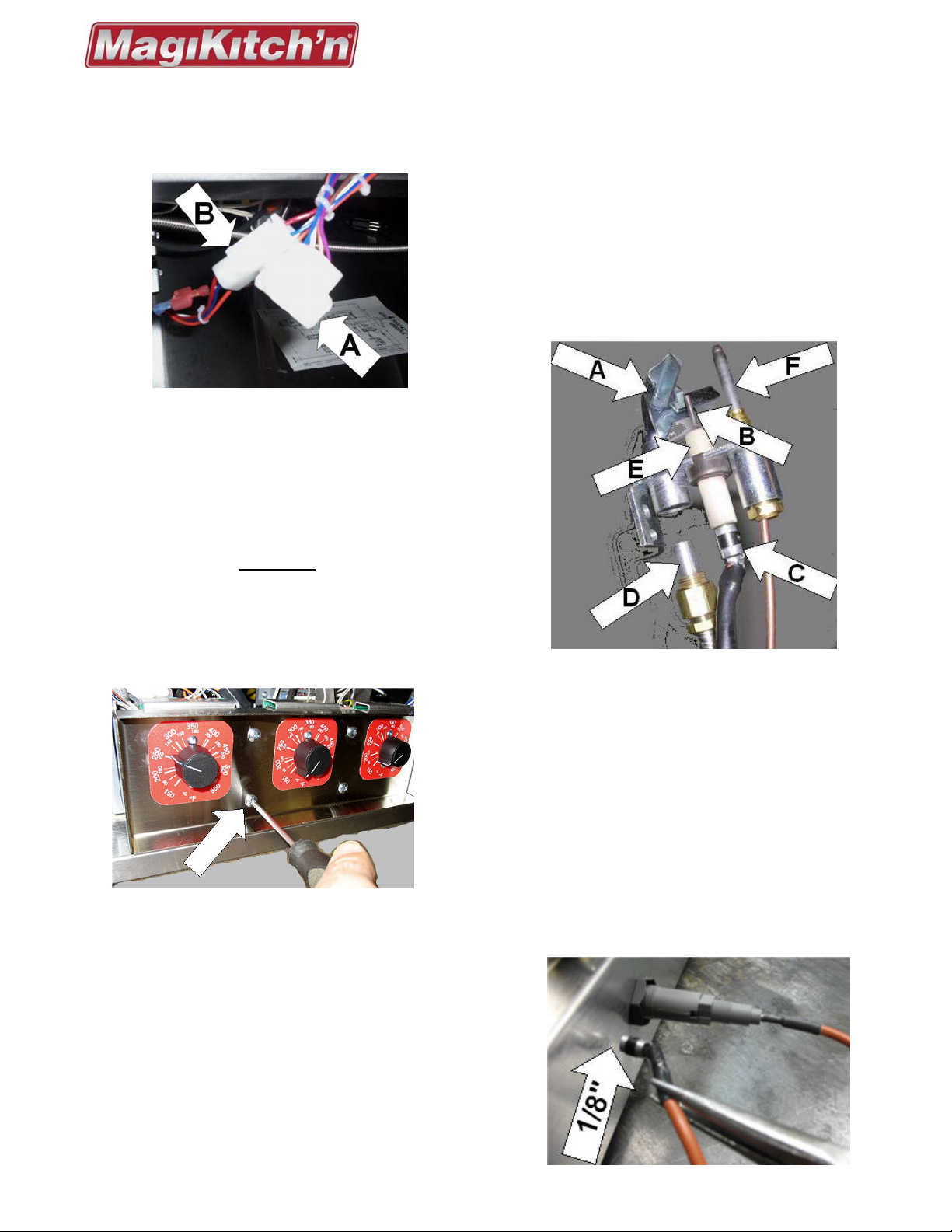
4.2 PILOT / IGNITION SYSTEM CHECK
4.2.1 Ignitor Check- Snap Action Series
Verify actuation of Piezo ignitor by depressing
red button on front panel, (A in Photo 1). A loud
“click” or “snap” sound should be detected.
Photo 15
L22-362 Rev 2 (11/12) Page 9
Page 10

Technical Service Manual
MKG/MKH/MKGD Series Gas Griddles
Install new Piezo ignitor in reverse order,
making sure to replace all hardware, and insure
all wires and gas tubing are re-connected to
original condition.
4.2.2 Spark Failure- Matchless (E & ST) Series
Turn on power switch, look and listen for a
steady arc from the pilot assembly. An unstable
arc may be caused by spark leakage, or an
insufficient gas supply to the pilot.
Spark leakage can be due to an excessive
spark gap between the pilot(A), and the
electrode(B), nominal gap is .090”. Damaged
parts, or a loose Ignition wire at the spark
terminal(C), may result in spark leakage also,
See Photo 16.
Photo 16
Inspect all parts and wiring connections for form
fit, function, and repair or replace as needed.
Insufficient gas supply to the pilot can be
caused by a dirty pilot orifice(D), or insufficient
gas supply pressure. The gas for the pilot line is
supply from the incoming gas supply before the
regulator that controls the manifold pressure.
Disconnect pilot tubing from pilot to access the
pilot orifice(D), the pilot orifice is threaded into
the pilot(A), use an open end wrench to remove
the orifice, clean or replace as needed.
The pilot mounting bracket (E) shown in photo
16 is for MKH models. The pilot Bracket may
appear differently for MKG and MKGD models.
If no spark is evident, check for 24 VAC to the
ignition module between the 24V terminal (A)
and chassis ground, also verify all other
ground connections, See Photo 17.
Photo 17a
Access to the ignition module (A), can be
gained by removing two (2) self tapping
screws (B) to dismount the mounting bracket,
wiring not shown for clarity, see Photo 17a.
If 24 VAC IS NOT
present at the ignition
module, check that the external power cord (B)
is plugged in to live 115V outlet, and securely
plugged into the power supply box (A). Check
all connections for any jumper cords (C) that
may be present to see that they are tight, and
securely fastened into the power supply box
(C), See photo 17b.
If 24 Vac is still not present at the ignition
module, check the 24 Vac inline fuse for
continuity, it is located on the output side of the
power supply box. Also check the output
voltage of the transformer located in the power
supply box, refer to section 4.13.
If 24 VAC IS
present at the ignition module,
but no spark generated, replace the ignition
module, See Section 4.3.
Photo 17
Page 10 L22-362 Rev 2 (11/12)
Page 11

Technical Service Manual
MKG/MKH/MKGD Series Gas Griddles
4.2.3 Insufficient or Absence of Flame:
An insufficient pilot flame can result in a loss of
flame sense to the ignition module on a
Matchless ignition appliance, or loss of
sufficient mill voltage to actuate the safety valve
on a Snap Action appliance.
Photo 18
Look through the pilot view ports and check for
the pilot flame originating from the pilot hood
(A). A strong flame should visibly extend above
each pilot runner tube (B). If flame is not visible,
the ignition system may fail to activate the main
burner system See Photo 18.
the gas regulator. Pilot gas flow on matchless
ignition models can be adjusted with a needle
valve (A, in photo 18a) to increase pilot flame
after all pressures have been verified at the
nominal settings.
Pilot orifices can be checked by disconnecting
the ¼” tubing from the pilot assembly, (D, in
Photo 14 for Snap Action, and D, in Photo 16,
for Matchless Ignition models. Refer to section
4.4 for pilot removal from the appliance.
The gas flow to the pilot can be checked by
connecting a manometer to the disconnected
¼” tubing going to the pilot. Refer to Section 2
for each model to initiate gas flow to the pilot.
4.2.4 Pilot Lock-in: Snap Action Series
If a sufficient pilot flame is present, but the
main valve will not engage, check the millivolt
output of the thermocouple (F, in Photo 14) .
Disconnect the thermocouple contact (D, in
Photo 41) from the safety valve and measure
the output between the contact and ground.
Open circuit output should be greater than
15mv. closed circuit should be greater than
8mv (thermocouple connected).
Note: To measure a closed circuit use of a
thermocouple test adapter. The thermocouple
contact must not be cross threaded, and must
be tightened to1/4-1/2 turn past finger tight.
If the millivolt output does not meet the
minimum voltage, replace thermocouple.
Photo 18a
Common causes of insufficient pilot flame are
NO,
or LOW gas supply pressure, a pilot orifice
that has become clogged with foreign debris.
Verify gas pressure at the manual shut off
valves, (C), in Photo 1 for Snap Action models,
and (C), in Photo 2a for Matchless Ignition
models. The table in Section. 1.2.1 has the
nominal gas pressure for each gas type.
Pilot gas supply on matchless ignition models is
supplied before the gas regulator. The gas
pressure should be the nominal supply
pressure listed for the type of gas being used.
If the thermocouple is properly connected, and
the millivolt output is sufficient (25-35mV, No
Load), but safety valve will not engage,
replace the safety valve, see section 4.11.
If pilot flame and millivolt readings are normal
but there is no flame at the main burner, check
thermostat operation, refer to section 4.9.1.
Photo 19
Pilot gas flow on snap action models cannot be
adjusted since it is dependant on the setting of
L22-362 Rev 2 (11/12) Page 11
Page 12

Technical Service Manual
MKG/MKH/MKGD Series Gas Griddles
4.2.5 Pilot Lock-in- Matchless Series (E & ST)
The electronic ignition system is an integral
flame sense system. This means that the
module supplies spark, and senses flame
current with the same electrode. The pilot
assembly, ignition module, and the appliance
must be properly grounded to operate properly.
The ignition module is grounded to the chassis
directly at the pilot bracket (A, in Photo 19). The
appliance is equipped with a NEMA 5-15
grounded plug, extension cords are not
recommended for use with the appliance.
Photo 20
When properly grounded, and adequate pilot
flame are established as described in section
4.2.2, but spark continues for 90 seconds
followed by an ignition module lock out, there is
a flame sense failure. Replace the ignition
module as described in section 4.3.
Photo 21
4.3 IGNITION MODULE REPLACEMENT
Remove the two (2) self tapping screws (A)
holding the ignition module bracket in place,
See Photo 20. Take care not to damage any
wiring or terminals.
Disconnect ignition wire (B) from the spark
terminal, and control wiring (C) from the 24 Vac
terminal by carefully pulling upward on the wire
terminals with electrical pliers. It is advised to
label the wires to avoid miss wiring the new
ignition module.
Remove module from the bracket by removing
the two (2) 6-32.mounting screws (B), See
photo 20.
Mount the new module to the bracket with the
6-32 screws removed from the old module.
Wire the module with the 24Vac control wiring,
and the high voltage ignition wire. Refer to the
schematics in Section 5 of this manual to avoid
miss wiring the control.
Remount the assembly back onto the
component bracket. Take care to route the
wiring harness to avoid straining terminal
connections or pinching wires.
4.4 PILOT ASSEMBLY REPLACEMENT
Pilot assemblies and are held in place by two
(2) screws (A). The assembly can be accessed
from under the burners, See Photos 19.
Remove the Ignition wire (C), the ignition wires
may appear differently between snap action
models, and matchless ignition models.
Loosen gas line fitting (B) prior to removing
mounting screws (A). The screws will stabilize
the pilot assembly during this procedure.
Remove the mounting screws (A) and pull pilot
assembly down until clear from burner
chamber. Remove the tubing and change
orifice and pilot burner as needed.
Install new assembly in reverse order, verify
nominal spark gap, see sections 4.2.1 & 4.2.2.
4.5 BURNER ADJUSTMENTS
To maintain optimum griddle performance, the
burners, and burner manifold must be properly
aligned, and the air inlets free of debris.
Misalignment of the burner manifold (D), or an
obstructed air shutter (B) opening can cause
incomplete combustion, or yellow flames at the
burner ports, See Photo 22.
To align the burner manifold (D), loosen, or
tighten manifold Bracket screws (E) until the
manifold orifices are in line with the burners.
The air shutters (B) are opened fully for all gas
types, if flames appear yellow, check for any
obstruction in the air inlet, clear as necessary.
If flames appear to blow off the burner ports,
loosen the air shutter screw (C) adjust shutter
(B) CCW until flames settle down, then
retighten the screw(C). If yellow flame occurs,
adjust the air shutter(B) CW until all flames are
blue. Note: The appliance must be cold when
making this adjustment.
If appliance is hot, above 300°F., make certain
that burner flame cones are well defined and
Page 12 L22-362 Rev 2 (11/12)
Page 13

Technical Service Manual
MKG/MKH/MKGD Series Gas Griddles
that there are NO yellow flames. If yellow flame
appears, open air shutters gradually until
flames are blue. Check for proper burner
ignition after allowing the appliance to be off for
10 minutes. Note: Proper ignition is when all
burner ports are lit within 4 seconds.
4.6 ORIFICE/FUEL TYPE CONVERSION
Poor performance may be an indication of a
clogged or damaged burner orifice that needs
replacement. In addition, the gas type of the
appliance may need to be changed to another fuel,
see section 1.2.1 for approved gases.
While securing the manifold in a safe manner,
remove the two main burner orifices( A), and
the runner tube orifice(B). Take care to not
damage the brass fittings or pipe threads, See
Photo 24.
Prior to installing the new orifices, insure that
the fittings are not clogged, and reapply thread
sealant to all male threads where necessary.
Install new orifices onto manifold as stated
above, if no further service is required replace
manifold to original position.
Photo 24
Photo 22
4.6.1 Changing Burner Orifice
To replace clogged, or convert burner orifices follow
the steps below: Refer to section 1.3.2 to check the
proper orifice size for the appliance.
After the upper front panel has been removed,
remove the mounting screws (E), then slide the
manifold bracket(D) off of the burner manifold,
See Photo 22.
If Converting Fuel Type, continue here:
Change orifices as described in section 4.6.1.
Change pilot assembly, see section 4.4.
Change the gas supply regulator (D, photo’s
1a & 2a), a new regulator will require thread
sealant on all mating male threads.
Perform a gas leak test, and check operating
gas pressure of the appliance, see section
1.2.1. Insure that burners are operating in
accordance with section 4.5.
Place the appropriate information label stating
the change in fuel type of the appliance in
close proximity to the data plate, or other
prominent area.
4.7 MAIN BURNER REPLACEMENT
If a burner needs to be removed for replacement
or cleaning, use the following procedures:
Disconnect the manifold supply tubing at the
brass compression fitting(A). the manifold will
slide out of the burners and runner tube, See
Photo 23. Note the thread engagement of the
orifices for reinstallation, See Photo 24.
Photo 25
L22-362 Rev 2 (11/12) Page 13
Page 14

Technical Service Manual
6
MKG/MKH/MKGD Series Gas Griddles
Remove the manifold, see section 4.6.1.
Remove the mounting screws (C) from the pilot
cover plate (A), and the burner seal plate (B),
See Photo 25.
Note: Some burners may require two (2) pilot cover
plates to be removed to access the burner(s).
Photo 2
Remove the pilot cover plate and the burner
seal plate and set aside for reuse later.
Remove the runner tube mounting screws(C)
and remove the runner tube and set aside, See
Photo 26. There are left and right hand pilot
runner tubes so take care to keep parts
identified for reinstallation.
Lift up the burner (B) to be removed slightly and
pull straight out through the front of the griddle,
See photo 27. The will slide off the indexing pin
located at the rear of the burner mount bracket.
Install the replacement burner into the mounting
bracket.
4.8 GAS PRESSURE ADJUSTMENT
Before checking the operating pressure of the
appliance, the incoming supply pressure to the
appliance must be verified. The minimum dynamic
pressure for natural gas is 5.0” WC, and LP gas is
11.0” WC.
Important! Make sure the manual shut off valve
is in the closed position prior to making any
test connections.
With the shut off valve is closed, connect a
manometer to the pressure tap on the shut-off
valve (C), See Photo 29.
Note: On Snap Action models the shut-off is valve
behind the front panel, See Photo 1 in section 2.1.
Photo 29
Open the shut of valve and verify the incoming
pressure as stated in section 1.2.1.
If incoming supply pressure is correct the
Photo 27
Make certain that the end of the burner (B) is
located on the indexing pin (A) of the burner
mounting plate, See Photo 28.
Re-install the remaining screws, runner tube
and sheet metal in reverse order. Insure that all
burners, runner tubes, and pilots have been
properly positioned for optimum performance
after the repair.
manifold gas pressure can be adjusted as
needed.
NOTE: A properly sized and installed gas line will
deliver a minimum supply pressure of 7.0” W.C.
(17.4mbars, 1.74kPa) natural gas or 11.0” W.C.
(27.4mbars, 2.75kPa) propane to all appliances
connected to the supply line, operating at full
demand. If regulated gas pressure cannot be
achieved with all appliances in the store running,
there may be a building gas supply deficiency.
Page 14 L22-362 Rev 2 (11/12)
Page 15

Technical Service Manual
MKG/MKH/MKGD Series Gas Griddles
The gas pressure regulator on matchless
ignition models is located behind the right hand
lower panel at the front of the unit, (See D in
Photo 2b). The manifold pressure is checked at
the pressure tap (E), see Photo 29.
The gas pressure regulator (D) on snap action
models is located in the rear of the unit. The
manifold pressure is checked at the shut off
valve pressure tap (C), see Photos 1 & 1a.
Photo 29a
To adjust manifold pressure, remove the
regulator cap (A), to expose adjustment screw
(B). Turn CW to increase pressure, or CCW to
decrease pressure, See Photo 29a.
The pressure should be adjusted while all the
burners are “ON”, set the manifold pressure in
accordance with section 1.2.1.
If gas pressure will not change, verify that vent
fitting (C) is free from grease or debris. The
vent has a hole in the side of the fitting.
If supply pressure is adequate, but proper
manifold pressure cannot be obtained, replace
regulator.
Photo 30
4.9 TEMPERATURE CONTROLS CHECK
4.9.1 Snap-Action Models
If there is no burner response when the
temperature control has been activated, verify that
gas is supplied by the safety valve as follows:
Remove front panels, refer to Section 4.1.
Turn off gas at the manual shut-off valve, See
Photo 1.
Disconnect 3/8” supply tubing from thermostat
inlet (A), and attach pressure test equipment to
open tubing, See Photo 30.
Light the pilot and engage Safety valve, refer
to Section 2.1.
Once the safety valve is engaged, gas should
flow through the 3/8” tubing (A) and there
should be a pressure reading at the
manometer. If there is pressure at the 3/8” inlet
tubing (A) the safety valve is operating, and
the thermostat gas flow should be verified. If
there is no pressure indicating gas flow, test
the operation of the safety valve (D, Photo 30),
refer to Section 4.2.4.
Shut down the appliance in accordance with
the operators manual and reconnect the inlet
tubing (A) to the thermostat.
Disconnect the thermostat outlet fitting (B),
and connect a manometer to the brass elbow.
Light the pilot and engage Safety valve, refer
to Section 2.1.
Turn the thermostat (C) on and check for gas
pressure at the outlet fitting (B), If there is no
gas pressure coming from the outlet replace
the thermostat, refer to Section 4.10.1
4.9.2 Matchless “E” Models
If there is no burner response after start up, verify
electrical supply to the Electric thermostat control
and operation of the contacts as follows:
Remove the lower front panel(s), refer to
Section 4.1.2.
Light pilots as in Section 2.2, when pilots are
lit, turn all thermostats to the “Off” position.
Using a voltmeter, check for 24 VAC input to
the thermostat (A), measure across the orange
wire (B) and Chassis Ground, See Photo 31.
If voltage is not present and the pilots are
operating, verify 24 VAC output voltage from
MV terminal (D) on the ignition module, See
Photo 32. If there is no voltage at MV terminal
check the function of the ignition module, refer
to Section 4.3.
If voltage is present at the MV terminal, check
the operation of thermostat contacts by
measuring an electrical open/close of contacts
when turning the thermostat “Off” and “On”.
Measurements are taken between contacts(B
& C). Resistance continuity can also be tested
L22-362 Rev 2 (11/12) Page 15
Page 16

Technical Service Manual
MKG/MKH/MKGD Series Gas Griddles
across these contacts by turning off electrical
power and disconnecting one wire from
terminal B or C, See Photo 31.
Photo 31
If temperature controls fail to respond, or
cannot be calibrated to operate according to
Section 3.2, replace control, refer to Section
4.10.
4.9.3 Matchless “ST” Models
If there is no burner response, verify electrical
supply to the Solid State control and operation of
the contacts as follows:
Photo 33. (Note: The white wires (B) is the
common Neutral wire.
If there is no voltage at the blue wire (A)
terminal check the output of the corresponding
rocker switch on the upper panel.
If there is no voltage present at the orange
wire (D) terminal, check output voltage of MV
terminal at the ignition module (The other end
of orange wire), See Photo 32.
If 24-volt input is measured at both the blue
and orange wires, check for 24 volt output on
the gray or violet wire (C) with the control set
to the maximum temperature setting. This
output supplies voltage to the gas solenoid for
the main burners.
Photo 33
Photo 32
Remove the lower front panel(s), refer to
Section 4.1.2.
Light pilots as in Section 2.2, when pilots are lit,
turn all controls to the minimum temperature
setting until the next step.
Turn the control to the maximum temperature
setting, Using a voltmeter, check for 24 VAC
across the blue wire (A), and white wire (B)
terminals. Also check for 24 VAC across the
orange wire (D) and white wire (B) terminals.
Voltage is necessary on both input lines, See
If there is no output voltage on wire terminal
(C), then check the sensor probe for the
proper resistance, Refer to Section 4.9.4.
If all the above conditions are satisfactory and
no main burner response, refer to Section
4.10.3 to replace the control.
4.9.4 Temperature Probe Check:
Resistance of the Temperature Probe changes as
the temperature changes. As temperature rises,
the probe’s resistance decreases.
If the probe is suspect, remove wire
connections (E) from the Solid State
temperature control, See Photo 33.
Using a multi-meter, check the probe
resistance against the cooking surfa ce
temperature. Use the Resistance Chart in
Section 4.9.5 to compare the two values.
Note: Measure surface temperatures
according to section 3.1.
If the probe measures open circuit (OL),
shorted (0 Ohms), or if the resistance is +/-30
Ohms from the chart value, replace the probe,
refer to Section 4.10.4.
Page 16 L22-362 Rev 2 (11/12)
Page 17

Technical Service Manual
MKG/MKH/MKGD Series Gas Griddles
Remove the Pilot cover plates and burner seal
plates to access thermostat sensor, Refer to
Section 4.7.
NOTE: Do not remove bulb clamp.
Loosen the sensing bulb clamp(A) from griddle
plate by removing the two (2) mounting
screws(B). This bulb clamp is spring loaded
and the sensing bulb can be removed by
pushing downward on the bottom edge(C) of
the clamp, See Photo 34.
Photo 35
IMPORTANT! Before performing any
service to this appliance, make sure any
4.9.5 Resistance Chart: Solid State
Thermistor Probe
Degrees
Celsius
(°C)
Degrees
Fahrenheit
(°F)
Resistance
Ohms ()
0 32 1000.000
20 68 1077.928
40 104 1155.392
60 140 1232.392
80 176 1308.928
100 212 1385.000
120 248 1460.608
140 284 1535.751
In
Gas or Electrical supplies are turned off
and disconnected
Pull the sensing bulb “Out & Down” from the
slot, the loosened bulb clamp will move so the
bulb can be removed.
With the sensing bulb removed, the control can be
disconnected and removed from the appliance:
Disconnect inlet(A) and outlet(B) gas tubing
from thermostat.
Remove mounting screws(C), save for re-use.
Install replacement thermostat in reverse
order. Make certain that there is no strain on
the flexible gas tubing, or the capillary line for
the thermostat.
160 320 1610.430
180 356 1684.645
200 392 1758.396
220 428 1831.683
240 464 1904.505
NOTE: For best results check while the unit is hot,
between 320-374°F, (160-190°C).
4.10 TEMPERATURE CONTROL
REPLACEMENT
4.10.1 Snap Action Models
The thermostat sensing bulb is pressed into a
slot on the underside of the cooking surface.
The sensing bulb should be removed from this
slot first:
Remove the burner manifold bracket, and
burner manifold for the corresponding control to
be replaced. Refer to Section 4.6.1.
Insure that the sensing bulb is seated firmly up
into the slot prior to securing the bulb clamp in
position.
Photo 36
4.10.2 Matchless “E” Models
Remove sensing bulb according to section
4.10.1
Carefully disconnect the “push-on” wire
terminals(B&C) from the thermostat with
needle nose pliers or other adequate tool,
Photo 31.
Pull the thermostat knob off the thermostat
shaft. Remove the thermostat from the
mounting bracket by removing the two
Photo 34
exposed screws(A) found under the knob, See
Photo 37.
L22-362 Rev 2 (11/12) Page 17
Page 18

Technical Service Manual
MKG/MKH/MKGD Series Gas Griddles
NOTE: If necessary, the thermostat mounting
bracket can be carefully dismounted to allow
additional access to the controls.
Install replacement thermostat in the reverse
order.
CAUTION: Do not allow the capillary to short
circuit electrical connections.
Photo 37
4.10.3 Matchless “ST” Models
Remove the Solid State control knob by
loosening the locking nut(A, Photo 8) under the
knob cap(A, Photo 7).
Pull the control knob off the shaft. Remove the
Solid State control from the mounting bracket
by removing the two exposed screws(A) found
under the knob, See Photo 38.
Carefully disconnect the wires from the Solid
State control with needle nose pliers or other
adequate tool, See Photo 33).
4.10.4 Thermistor Probe Replacement
The Solid State control has a separate
temperature sensing probe, the thermistor probe
can be removed without removing the Solid State
control.
Remove the upper panel assembly according
to Section 4.1.2.
Remove the burner manifold bracket, Pilot
cover plate, and the burner seal plates
according to Sections 4.6 & 4.7.
Photo 39
Remove the two (2) screws (A) that hold the
probe retention plate in place, See Photo 39.
Slide the probe and plate outward together.
Disconnect the probe wires (E) from the Solid
State control, See Photo 33.
Photo 40
Slide the defective probe out from the retention
Photo 38
plate. Insert replacement probe into the
vacated hole of the plate to install together
Note: Label the wires for rewiring the control,
miss wiring could damage the appliance.
Install the replacement control in reverse order,
calibrate the control according to Section 3.2.2.
Locate the probe hole (A) in the rear of the
sensing bulb slot, carefully align, and slide the
thermistor probe all the way into the slot, See
Photo 40.
Slide the retention plate up to the “V” bracket
and align the mounting holes and secure with
“New” self tapping screws if available.
Page 18 L22-362 Rev 2 (11/12)
Page 19

Technical Service Manual
oto
MKG/MKH/MKGD Series Gas Griddles
4.11 SAFETY VALVE REPLACEMENT
Snap Action Models
If the test criteria from Section 4.2.4 have been met,
but the appliance does not operate properly,
replacement of the Safety valve may be required.
Shut off gas supply to appliance at the 1/2“
manual shut off valve(C), See Photo 1.
Remove the lower front panel(s) and the
temperature control panel, refer to Section
4.1.2.
Disconnect the pilot valve outlet tubing (B)
from the needle valve, See Photo 42.
Remove the two (2) mounting screws (A) that
hold the pilot gas in place. With the screws
removed you will be able to pull the pilot valve
towards you, be careful to not stress the
flexible pilot supply tubing, or the wire harness,
See Photo 42.
Ph
41
Disconnect 1/2” gas inlet(A) connection, 3/8”
gas outlet(B) connection(s), pilot gas outlet(C)
connection, and the pilot thermocouple(D)
connection, See Photo 41.
Note: Insure correct gas flow direction on the
replacement valve
Disassemble piping and fittings from defective
gas valve, and assemble onto the replacement
gas valve in the same orientation. Use pipe
sealant compound on all male threads.
Once piped, install the replacement valve into
the appliance. Re-secure all gas connections to
be leak free.
Re-attach the thermocouple to the safety valve
junction, take care to thread part correctly,
cross threading the junction may result in
component failure.
Test appliance for leaks, and proper operation
of the burner system.
4.12 SOLENOID VALVE REPLACEMENT-
Matchless Models “E” & “ST”
If all test criteria has been met according to
Section(s) 4.2.2 & 4.2.3, it may be required to
replace the either the pilot gas or main gas valve
solenoid.
4.12.1 Pilot Solenoid Valve
Disconnect the power cord from the electrical
supply, and shut of the gas supply at the
manual shutoff valve(C, Photo 2a).
Photo 42
Disconnect the 24 Vac supply wiring (A) from
the solenoid terminals, See Photo 43.
Disconnect the pilot valve outlet flexible
tubing(C) from the rear of the valve, See Photo
43. The valve and bracket can be removed
from the unit..
Photo 43
Remove the existing piping from the defective
valve, and install the piping and bracket onto
the replacement valve. Use Fluropolymer
thread tape where necessary.
Re-install the pilot valve assembly back into
the unit in the reverse order of removal.
The pilot solenoid(D), and the main burner
solenoid(E) are connected by a single pipe
nipple. Twist the two(2) solenoids apart and
replace the bad component.
L22-362 Rev 2 (11/12) Page 19
Page 20

Technical Service Manual
MKG/MKH/MKGD Series Gas Griddles
4.12.2 Main Burner Solenoid Valve
To replace a faulty main burner solenoid valve it
may be required to disconnect both of the main
burner solenoids from the gas valve assembly.
Some assemblies may only have a single main
burner solenoid.
Disconnect the power cord from the electrical
supply, and shut of the gas supply at the
manual shutoff valve(C, Photo 2a).
Remove the lower front panel(s) and the
temperature control panel, refer to Section
4.1.2.
Label the wiring (A) on the solenoid valves to
avoid miss wiring the valves. miss wiring the
solenoid valves can cause damage to the unit,
and cause the unit to operate improperly.
Remove the two (2) mounting screws (D)
holding the solenoid valve brackets to the
assembly, See Photo 44.
The valve assembly is not completely
disconnected, the inlet tubing to the solenoid
valves is still connected in the rear of the
valves. Gently move the assembly aside,
taking care not to strain the flexible inlet
tubing.
Disconnect the 3/8” Flexible inlet tubing (E),
See photo 45. Single valve assembly shown
for clarity. The valve assembly is now free
from the unit and the valves may be
disassembled.
Photo 44
Disconnect the wiring (A) from the solenoid
valves. Place the wiring neatly to the side to
avoid damaging the wires, See Photo 44.
Label and disconnect both of the 3/8” flexible
outlet tubing to the burner manifolds, first tubing
(B), then tubing (C), See Photo 44.
Photo 45
Photo 46
Remove the existing piping from the defective
valve(s), and install the piping and bracket
onto the replacement valve. Use Fluropolymer
thread tape where necessary, See photo 46.
Page 20 L22-362 Rev 2 (11/12)
Page 21

Technical Service Manual
MKG/MKH/MKGD Series Gas Griddles
4.13 POWER SUPPLY TRANSFORMER
MATCHLESS MODELS “E” & “ST”
There is one (1) power supply box with a 80 VA
transformer that controls one (1) ignition module
and gas valve assembly. Each additional module
and valve assembly are connected to the 120 Vac
supply with IEC jumper cables.
4.13.1 Power Supply Transformer Check
To check the operation of the transformer first
check the inline fuse (A), See Photo 47.
Prior to replacing the transformer, inspect all
the wiring for damage, and make sure all
connections are secure.
4.13.2 Power Supply Transformer
Replacement
Disconnect the power cord from the electrical
supply.
Disconnect the power cord (B), and the IEC
jumper cable (C) from the power supply box to
be serviced, See Photo 17b.
Disconnect the Vac connection (A) to the
control circuitry of the appliance, See Photo
48. Access to the connection is from the rear
of the unit, the red arrows display a path.
Photo 47
Disconnect the power cord from the electrical
supply.
Remove the lower front panel(s), and the
temperature control panel if needed, refer to
Section 4.1.2.
With the panels removed, disconnect the inline
fuse (A) from the switch panel at the .250” red
terminal (B) that corresponds with the
transformer box being tested, See Photo 47.
Place the terminal in a location where it will not
short out to adjacent panels or components and
plug in the 115 Vac power cord into a
functioning outlet.
Using a voltmeter, check for 24 Vac between
inline fuse terminal (B), and chassis ground. If
voltage IS
present the transformer and fuse are
functioning properly.
If voltage IS NOT
present, unplug the 115 Vac
plug from the outlet and remove the 2A fuse
from the inline fuse holder (A), See Photo 47.
Visually inspect the fuse, and using an
Ohmmeter for resistance continuity across the
fuse. If there IS NOT
continuity, replace fuse
and recheck for voltage at the fuse terminal (B).
If there IS
continuity through the fuse, the
transformer may be defective and need to be
replaced.
Photo 48
With the power cord(s) and control wiring
disconnected, dismount the power supply box
from the appliance by removing the front
mounting screw (B, See Photo 48), and the
rear mounting screws (A, See Photo 49).
Note: A 5/16” nut driver or socket is
recommended to remove these screws.
Photo 49
Pull power supply box out of the cabinet and
turn over to access the transformer.
L22-362 Rev 2 (11/12) Page 21
Page 22

Technical Service Manual
5
MKG/MKH/MKGD Series Gas Griddles
Remove the two (2) 10-24 screws (A) that
secure the transformer in the power box and
set aside, then remove the old transformer from
the box. Take care not to put excessive strain
on the connections, See Photo 50.
The wiring connections (B), should be labeled
prior to disconnecting the wires from the
terminals, See Photo 50.
Photo 50
Install the replacement transformer into the
power supply box in reverse order.
Re-install the transformer and the power supply
box with all the removed hardware.
Ensure that all wiring connections are correct
and secure. If any strain relief materials were
removed, make sure to properly secure all
wiring to its original condition.
4.14 SWITCH AND LAMP REPLACEMENT
The upper front panel is where the power switches
and the pilot ready lights are mounted. If the lamps
or switches are damaged, do not illuminate, or
malfunction they should be replaced,
The Pilot ready light (A) will illuminate when
ignition module flame sense has been satisfied.
The power switch (B) will illuminate when the
temperature control for that zone activates the
main burner solenoid valve, See Photo 51.
Remove the Upper and lower front panels as
shown in Section 4.1.2.
With all other components functioning properly,
the pilot ready light (A), should illuminate when
there is 24 Vac across the orange and white
wires connected to the lamp terminals, See
Photo 52.
The power switch (B) will illuminate when there
is 24 Vac across the wire at terminal 5, (red or
red w/ white wire), and the white wire at
terminal 3, refer to schematics in Section 5 for
further information.
To replace a damaged or faulty lamp, first
disconnect the wiring (A) from the terminals on
the lamp. Remove the retaining nut (B) that
Photo
2
secures the lamp to the panel, the lamp can be
removed and discarded. Install replacement
lamp in reverse order, See Photo 53.
To replace a damaged or faulty power switch
label and disconnect the wiring (A) from the
switch terminals. Notice the orientation of the
switch in the panel for reference in installing
the replacement switch, See Photo 54.
Photo 53
Pry the 4 prongs at the corner of the switch
down, and push the switch out of the cutout.
Install the replacement switch in reverse order,
refer to schematics in Section 5 for further
information, See Photo 54.
Photo 51
Photo 54
Page 22 L22-362 Rev 2 (11/12)
Page 23

Technical Service Manual
MKG/MKH/MKGD Series Gas Griddles
5 TROUBLESHOOTING GUIDE
5.1 TROUBLESHOOT GUIDE -SNAP ACTION MODELS
Problem Cause Corrective Action
1. Check that all gas connections are turned
on, and verify gas pressure at the regulator.
2. Verify gas supply, light pilot burner.
3. Turn thermostat to desired temperature.
4. Replace safety valve.
5. Replace thermostat.
1. Replace pilot assembly.
2. Replace pilot assembly.
3. Replace wire.
4. Replace Piezo ignitor.
1. Check that all gas connections are turned
On, verify gas pressure at the regulator.
2. Verify that all connections are fully
Engaged and leak free.
3. Verify that the shut off valve is fully open.
4. Replace safety valve.
1. Calibrate thermostat.
2. Replace thermostat.
3. Set incoming gas pressure according to the
appliance data plate.
4. Verify gas type, Discontinue use until
1. Level cooking surface.
2. Set incoming gas pressure according to the
appliance data plate.
3. Divert drafts away from flue outlet.
4. Diagnose problem with use of this guide
and repair as needed.
Griddle won’t heat.
No pilot spark
No pilot gas
Temperature too low
or high
Griddle surface has
inconsistent
temperatures.
1. No gas supply.
2. No pilot flame.
3. Thermostat turned off
4. Safety valve defective.
5. Thermostat defective.
1. Wrong spark gap.
2. Defective electrode.
3. Defective ignition wire.
4. Defective Piezo ignitor.
1. No gas to Safety valve.
2. Faulty gas connection.
3. Manual shut off closed.
4. Defective Safety valve.
1. Thermostat out of
calibration.
2. Defective thermostat.
3. Incorrect gas pressure.
4. Wrong gas/fuel type.
1. Appliance is out of level.
2. Incorrect gas pressure.
3. Excessive drafts on flue
outlet.
4. A section of the griddle may
be out of service..
L22-362 Rev 2 (11/12) Page 23
Page 24

Troubleshooting Guide
MKG/MKH/MKGD Series Gas Griddles
5.2 TROUBLESHOOT GUIDE - E / ST SERIES
Problem Cause Corrective Action
1. Appliance power cord, Check power at wall
outlet, check appliance fuse.
2. Refer to “Pilot Lock-in” section of manual.
3. Check gas supply pressure, quick disconnect
engagement, shut off valve and regulator.
4. Check actuation and electrical input/output of
part. Replace if defective.
5. Same as 4.
1. Plug in power cord to grounded wall outlet
2. Reset breaker
3. Replace or reconnect appliance inline fuse.
4. Replace Switch.
1. Check for 24 VAC. at module connection.
2. Check connections at both ends of wire and test
for continuity. Replace if defective.
3. Check electrode for damage and correct spark
gap (.090”). Listen for any spark leakage.
replace/repair as needed.
4. Check for continuity between griddle body and
ground prong on plug. Verify internal ground
connection. Replace power cord if ungrounded.
1. Check pilot solenoid valve, check incoming gas
supplies.
2. Set gap to 1/8” (.125”)
3. Check electrode for damage, replace as needed
4. Check all power connections to have a 3 prong
grounded power cord. Note: Extension cords
are not recommended for use with this
appliance.
5. Check supply plumbing for proper gas flow.
6. Make certain that quick disconnect fitting is fully
engaged and snapped in place.
7. Verify that shut off valve is in the open position.
8. Check wiring connections at pilot solenoid and
verify 115 VAC.
9. If voltage is supplied and valve remains closed,
replace solenoid valve.
Appliance won’t
heat.
No power
No pilot spark
Pilot will not stop
sparking
No pilot gas
1. No electrical power.
2. Pilot not lit, or dropping out.
3. Low gas pressure.
4. Thermostat malfunction
5. Gas valve malfunction.
1. Appliance unplugged
2. Wall circuit breaker tripped
3. Internal fuse blown or is
disconnected.
4. On/Off switch defective
1. No power to ignition module.
2. Ignition wire not connected.
3. Broken or bleeding electrode.
4. Improper grounding of
appliance.
1. No gas to pilot burner.
2. Spark gap incorrect.
3. Spark leakage
4. Un-grounded power cord
5. No gas supply
6. Quick disconnect not fully
engaged
7. Shut off valve closed.
8. No electrical input to pilot
solenoid.
9. Pilot solenoid closed
1. Thermostat out of calibration.
2. Thermostat is defective.
Operating
Temperature
incorrect
Page 24 L22-362 Rev 2 (11/12)
3. Solenoid valve defective.
4. Operating on wrong fuel type.
5. Appliance is out of level.
6. Incorrect gas pressure.
7. Drafts on outlet of flue.
8. A zone not heating properly.
1. Refer to calibration section of this manual.
2. Replace thermostat.
3. Replace solenoid valve.
4. Discontinue use. Convert to proper gas.
5. Level appliance in both directions.
6. Refer to Section 1.3 of this manual.
1. Divert drafts away from flue outlet.
2. Diagnose with the use of this manual and repair
as needed.
Page 25

Trouble Shooting Guide
MKG/MKH/MKGD Series Gas Griddles
5.3 SCHEMATIC: MATCHLESS “E” SERIES
TABLE 3, T1
115VAC/60Hz
N
GND
SJTO
16 AWG
J13
TERMINAL
L
L
BLK
N
G
FRAME
WHT
2.5A
VOLTAGE
1
240 VAC
2
208 VAC
3
120 VAC
1
2
3
5
T1
6
10
FRAME
BLU
24 VAC
WHT
J/P10
3
2
1
BRN
LEFT
ON/OFF
S1A
2
S2A
2
RIGHT
ON/OFF
GRN/Y
WHT
MV1 LEFT
MAIN VALVE
MOV
WHT
PILOT VALVE
PV1
MOV
TYPICAL LAST BURNER
WHT
RED
D1B
GND
(5)
MV/PV
(10)
BGND
(4)
HV
(2)
PV
(3)
J/P1-2
J/P1-4
YEL
LT1
A
PILOT OK
P/N 601422801
GRY
HEAT
TC1
TEMP
CONTROL
3
3
BLU
ORG
J/P1-1
J/P1-3
LEFT
ON/OFF
5
6
7R8
S1B
ORG
MV
24V
(1)
(6)
K3
K1
P/N 60152001
IM1
IGNITION
MODULE
TYPICAL TWO BURNER SET
RIGHT
P/N 601422801
HEAT
TC2
TEMP
CONTROL
VIOL
ORG
WHT
ON/OFF
6
7 8
R
5
S2B
W/RED
D2B
J/P1-5
MV1 RIGHT
MAIN VALVE
MOV
L22-362 Rev 2 (11/12) Page 25
Page 26

Troubleshooting Guide
MKG/MKH/MKGD Series Gas Griddles
5.4 SCHEMATIC: MATCHLESS “ST” SERIES
115VAC/60Hz
N L
GND
SJTO
16 AWG
J13
L
N
G
BLK
FRAME
WHT
2.5A
TABLE 3, T1
TERMINAL
1
2
3
1
2
3
5
VOLTAGE
240 VAC
208 VAC
120 VAC
T1
6
10
FRAME
BLU
24 VAC
WHT
J/P10
3
2
1
BRN
LEFT
ON/OFF
S1A
2
S2A
2
RIGHT
ON/OFF
GRN/Y
WHT
MV1 LEFT
MAIN VALVE
MOV
WHT
PILOT VALVE
PV1
MOV
TYPICAL LAST BURNER
WHT
RED
D1B
GND
(5)
MV/PV
(10)
BGND
(4)
HV
J/P1-2
J/P1-4
(2)
PV
YEL
(3)
LT1
A
PILOT OK
24V(9)
COM (8)
GRY
NO (7)
HEAT
COM (6)
P/N 60142502
TC1
TEMP
CONTROL
31
SET POINT
3
3
BLU
2
CW
5
TP1
4
ORG
J/P1-1
J/P1-3
LEFT
ON/OFF
5
6
7
8
R
S1B
ORG
MV
24V
(1)
(6)
K3
K1
P/N 60152001
IM1
IGNITION
MODULE
TYPICAL TWO BURNER SET
RIGHT
24V(9)
COM (8)
HEAT
COM (6)
P/N 60142502
TC2
TEMP
CONTROL
31 2
NO (7)
ON/OFF
ORG
VIOL
WHT
5
TP2
4
5
6
7
W/RED
J/P1-5
D2B
8
R
S2B
MV1 RIGHT
MAIN VALVE
MOV
CW
SET POINT
Page 26 L22-362 Rev 2 (11/12)
Page 27

Trouble Shooting Guide
MKG/MKH/MKGD Series Gas Griddles
5.5 SCHEMATIC: MATCHLESS SINGLE POWER SWITCH “E” SERIES
TABLE 3, T1
115VAC/60Hz
N L
GND
SJTO
16 AWG
J13
TERMINAL
L
BLK
N
G
FRAME
WHT
2.5A
VOLTAGE
1
240 VAC
2
208 VAC
3
120 VAC
1
2
3
5
T1
6
10
FRAME
BLU
24 VAC
WHT
J/P10
3
2
1
BRN
D1B
RED
S1B
8 7
5
S1
2
GRN/Y
WHT
MV1 LEFT
MAIN VALVE
MOV
WHT
PILOT VALVE
PV1
MOV
TYPICAL LAST BURNER
WHT
J/P1-2
J/P4-2
J/P1-4
P/N 601422801
GRY
HEAT
ORG
J/P1-3
TC1
TEMP
R
6
3
WHT
J/P4-1
BLU
CONTROL
BLU
WHT
J/P1-1
MV
24V
(1)
(6)
K3
K1
P/N 60152001
IM1
IGNITION
MODULE
GND
(5)
MV/PV
(10)
BGND
(4)
(2)
PV
YEL
(3)
HV
TYPICAL TWO BURNER SET
MV1 RIGHT
P/N 601422801
HEAT
VIOL
ORG
J/P1-5
W/RED
MAIN VALVE
MOV
TC2
TEMP
CONTROL
NEXT PAIR
L22-362 Rev 2 (11/12) Page 27
Page 28

Troubleshooting Guide
MKG/MKH/MKGD Series Gas Griddles
5.6 SCHEMATIC: MATCHLESS SINGLE POWER SWITCH “ST” SERIES
115VAC/60Hz
N L
GND
SJTO
16 AWG
J13
L
BLK
N
G
FRAME
TERMINAL
WHT
2.5A
TABLE 3, T1
1
2
3
1
2
3
5
T1
VOLTAGE
240 VAC
208 VAC
120 VAC
6
10
FRAME
BLU
24 VAC
WHT
J/P10
3
2
1
BRN
D1B
RED
S1B
R
8 7
5
S1
2
GRN/Y
WHT
MV1 LEFT
MAIN VALVE
MOV
WHT
PILOT VALVE
PV1
MOV
TYPICAL LAST BURNER
WHT
J/P1-2
J/P4-2
GND
(5)
MV/PV
BGND
(10)
J/P1-4
(2)
PV
YEL
(3)
(4)
HV
24V(9)
COM (8)
GRY
NO (7)
HEAT
COM (6)
P/N 60142502
TEMP
CONTROL
6
SET POINT
3
WHT
J/P4-1
BLU
BLU
TC1
31
5
TP1
4
2
CW
WHT
J/P1-1
J/P1-3
ORG
MV
24V
(1)
(6)
K3
K1
P/N 60152001
IM1
IGNITION
MODULE
TYPICAL TWO BURNER SET
MV1 RIGHT
24V(9)
COM (8)
HEAT
COM (6)
P/N 60142502
TC2
TEMP
CONTROL
31 2
NO (7)
ORG
VIOL
5
TP2
4
J/P1-5
W/RED
MAIN VALVE
MOV
CW
SET POINT
NEXT PAIR
Page 28 L22-362 Rev 2 (11/12)
Page 29

Trouble Shooting Guide
MKG/MKH/MKGD Series Gas Griddles
Notes:
L22-362 Rev 2 (11/12) Page 29
Page 30

In the event of problems with or questions
about your order, please contact the
MagiKitch’n factory at:
(603) 225-6684 World Wide
Website Address:
www.magikitchn.com
MAILING ADDRESS – P.O. BOX 501, CONCORD, NH 03302-0501
SHIPPING ADDRESS – 10 FERRY ST., CONCORD, NH 03301
In the event of problems with or
questions about your equip ment, please
contact the MagiKitch’n Authorized
Service and Parts representative (ASAP)
covering your area, or contact MagiKitch’n
at the numbers listed to the left.
L22-362 Rev 2 (11/12)
 Loading...