

Page 1
Solid State Control Calibration Procedure
MKG Solid State Griddles - All Options
The following procedure describes the steps to calibrate the Solid State
Temperature Control for any of the MKG-ST Griddle Models.
L80-131 Rev 01
Page 2
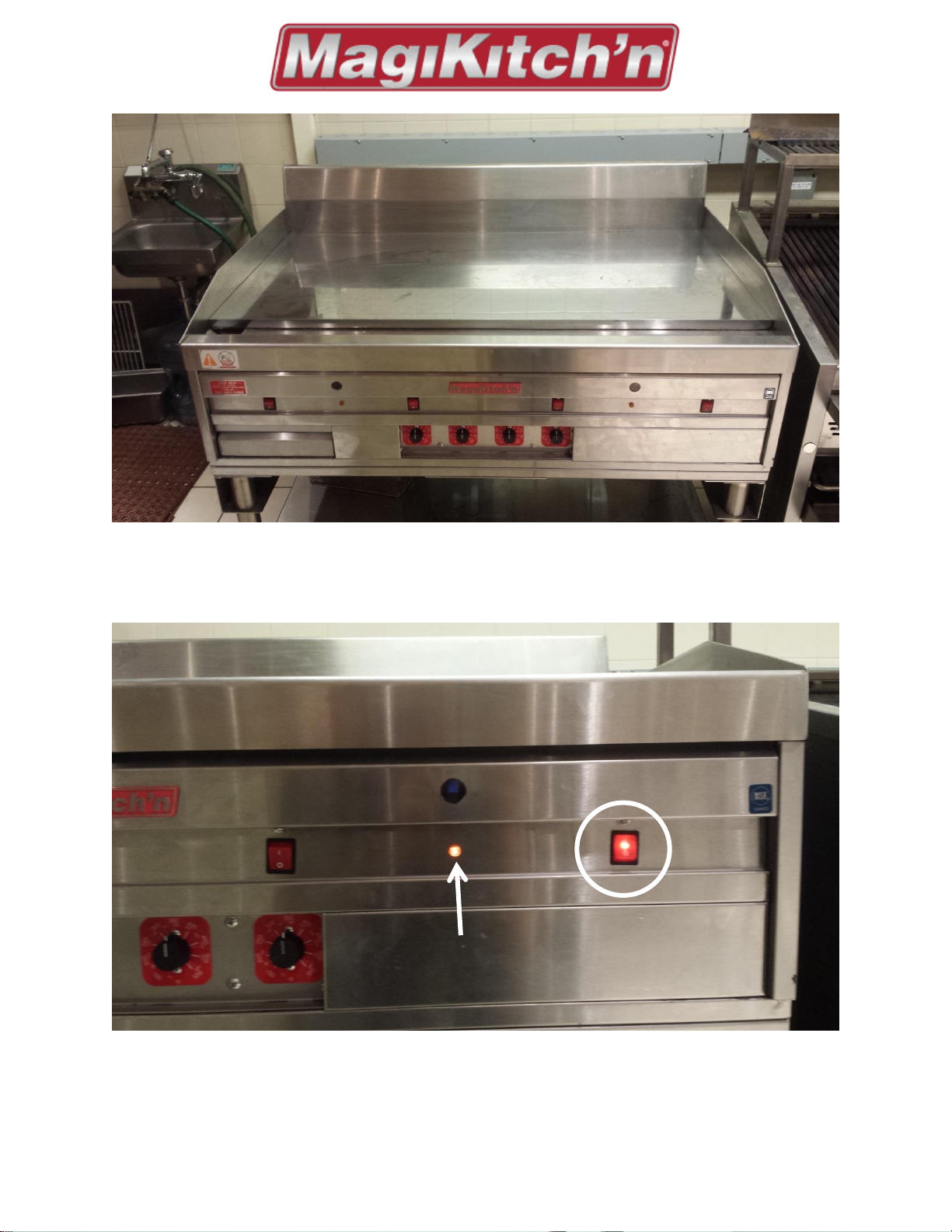
Figure 1: Verify that the unit is plugged in to the proper voltage outlet and is connected to the correct gas
type.
Figure 2: To validate that the unit is operational, turn on one set of burners by pushing the button (circled
above). Pilot should light and indicator light should illuminate (indicated by the arrow).
Page | 2 L80-131 Rev 01
Page 3
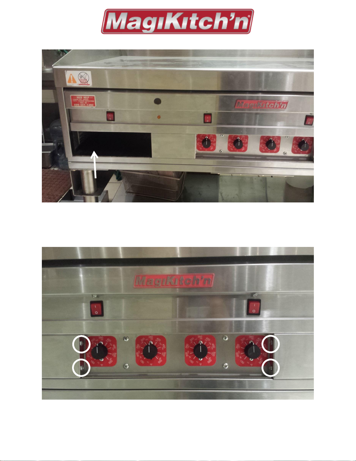
Figure 3: To gain proper access to the Thermostat wires, some disassembly of the unit is required. Start by
removing the grease pan, indicated above.
Figure 4: Next remove the four (qty. 4) Philips head screws, which will allow you to remove the front Left and
front Right panels.
Page | 3 L80-131 Rev 01
Page 4

Figure 5: Remove front Left and Front Right panels.
Figure 6: Remove four (qty. 4) Phillips head screws from the front the Solid State Control Panel, indicated with
arrows, as well as four (qty. 4) 3/8" hex head self-tapping screws from front panel (indicated with circles).
Page | 4 L80-131 Rev 01
Page 5

Figure 7: The front panel (indicated with arrow) will need to be removed to be able to lower the Solid State
Thermostat Control Panel, as shown above. Once removed, replace two (qty. 2) 3/8" hex head self-tapping
screws for ease of testing.
Figure 8: Now that the panel is lowered you can use the MagiKitch'n Solid State Thermostat Calibration Tool to
calibrate the controls. Verify that all switches are in the ‘OFF’ position.
Page | 5 L80-131 Rev 01
Page 6

Figure 9: Unplug the T-Stat wires from the first controller and replace it with the leads from the Calibration
test tool, as shown above (leads do not have to be in any certain order/position).
Figure 10: Flipping up the front panel to show the control knobs, switch the 350oF toggle into the ‘ON’
position. Burners should not ignite until 350oF is reach on the control knob.
Page | 6 L80-131 Rev 01
Page 7

Figure 11: With the 350oF Test Switch in the ‘ON’ position, as well as the units ‘ON/OFF’ switch in the ‘ON’
position turn the control knob until the unit turns on and burners ignite. Go beyond the temperature indicated
on the test controller, and then slowly back to the temperature on the switch. When the control knob is on
the left side of the line, as shown above, the unit should be off, indicating that the unit is at the indicated
temperature already. When the control knob is on the line of the indicated temperature or to the right of the
desired temperature, the unit should re-ignite the burners and come to the proper temperature.
Page | 7 L80-131 Rev 01
Page 8

Figure 12: If the control knob does not function as the previous steps indicate, remove the cap to reveal the
5/16" ferrule nut. This will allow you to fine tune the control knob to the proper level.
To calibrate the Knob, grab the knob firmly with one hand, using a 5/16" nutdriver or socket (B), loosen the
ferrule nut (A) on the control shaft. Make sure to limit the movement of the knob. This will allow the knob to
move freely, see above left. Once the knob is loose, rotate the knob so the indicator line is pointing at the
temperature where the heat was coming on. Once the knob is in place, snug the ferrule nut while holding the
knob firmly. Then reset the knob indicator line to the desired set point. Monitor when the heat comes on for
3-4 times, repeat procedure as needed until temperature is at the desired set point. When the calibration of
the control is satisfactory, tighten the ferrule nut completely. Replace the knob cap so that the indicator lines
are aligned with each other.
Page | 8 L80-131 Rev 01
Page 9

Figure 13: Once the control knob is in the correct spot, using the Calibration tool, verify that the control knob
works in the other two temperature locations.
Make sure to follow the same process as for verify at the 350oF temperature. Go beyond the temperature,
indicated by the switch in the ‘ON’ position, then back to the temperature on the switch. When the control
knob is on the line, as shown above, the unit should be off, indicating that the unit is to at the indicated
temperature already. Test again at the third and final test point.
Page | 9 L80-131 Rev 01
Page 10

NOTE: Make sure that all of the switches are in the off position before moving on
to the next temperature. If any of the switches are left on, meaning if there is
more than one switch on at a time, the unit will not turn on at any temperature.
Figure 14: Repeat all of the above steps for each of the Solid State Thermostat controls. Making sure to re-
install the units Thermostat plugs when complete with each controller (Thermostat wires do not have to be in
any particular order/position).
Once all of the controllers have been calibrated, the unit is ready for use. Follow the reverse procedure to
close the unit back up and re-install all of the correct components, screws, and pieces. Make sure to verify that
all electronic components are properly connected and snug.
Page | 10 L80-131 Rev 01
Page 11

Test Box Calibration/Verification Procedure:
Switch Order (Temperature, oF)
Designed Ohm Reading (Ohm)
Allowable Range (Ohm)
First (350o)
1673
1670 – 1685
Second (400o)
1775
1772 – 1787
Third (450o)
1876
1874 - 1889
Figure 15: To verify the calibration device, connect your multi meter/ohm reader as shown above.
1. Verify that when all switches are in the ‘OFF’ position that the device reads 0 Ohms (shown above).
2. Turn the first switch, 350
3. Turn the first switch, 350
o
F switch, into the ‘ON’ position and refer to table below.
o
F switch, into the ‘OFF’ position and the second switch, 400oF switch, to the
‘ON’ position. Refer to table for proper Ohm reading.
4. Repeat step three (3) for the 400
o
F switch and the 450oF switch. Refer to table.
5. If all values are within the allowed tolerance, device is accurate within 1% of actual temperature and
can be used to calibrate the Solid State Thermostat Controller Knob.
Page | 11 L80-131 Rev 01
Page 12

L80-131 Rev 01
 Loading...