

Page 1
IMPORTANT FOR FUTURE REFERENCE
Please complete this information and retain this manual
for the life of the equipment:
Model #: ___________________________
Serial #: ___________________________
Date Purchased: ___________________
Installation & Operation Manual
MKG24, MKG36, MKG48, MKG60 & MKG72
All Options
ENGLISH
I
S
G
E
N
D
C
E
E
R
I
T
F
I
CIRET IFED
D
L25-055 Rev. 0 (05/12)
Page 2
TO THE PURCHASER, OWNER AND STORE MANAGER
p
,
Please review these warnings prior to posting them in a prominent location for reference.
Post in a prominent location the instructions to be
followeed in the event that an operator smells gas. Obtain
this information from your local gas supplier.
DO NOT store or use gasoline or other flammable vapors
and liquids in the vicinity of this or any other appliance.
Do not spray aerosols in the vicinity of this appliance when
it is in o
Improper installation, operation, alteration, service or
maintenance can cause property damage, injury or death.
Read the installation, operating and maintenance
instructions thoroughly before installing, operation
Installation, maintenance and repairs should be performed by a
MagiKitch’n Authorized Service and Parts (ASAP) company
technician or other qualified personnel. Installation, maintenance
or repairs by unauthorized and unqualified personnel will void
the warranty.
Installation and all connections must be made according to
local codes in force. In the absence of local codes in North
America, the installation must conform with the Nat ional Fuel
Gas Code, ANSI Z223.1/NFPA 54 or the Natural Gas and
Propane Installation Code CSA B149.1 as applicable. In
Australia, the appliance must installed in compliance with
AS/NZS 5601.
During the warranty period if a customer elects to use a nonoriginal part or modifies an original part purchased from Pitco
and/or its Authorized Service and Parts (ASAP) companies, this
warranty will be void. In addition, Pitco and its affiliates will not
be liable for any claims, damages or expenses incurred by the
customer which arises directly or indirectly, in whole or in part,
due to the installation of any modified part and/or received from
an unauthorized service center.
This appliance, when installed, must be electrically grounded in
accordance with local codes, or in the absence of local codes,
with the National Electrical Code, ANSI/NFPA 70, or the Canadian
Electrical Code, CSA C22.2, as applicable and the hose must
comply with AS/NZS 1869 and be class B or D.
Adequate means must be provided to LIMIT the movement or this
appliance without depending on the gas or electrical cord
connection. Single appliances equipped with legs must be
stabilized by installing anchor straps. All appliances equipped
with casters must be stabilized by installing restraining chains.
An appliance equipped with casters and a flexible gas line must
be connected to the gas supply with a quick disconnec t device.
In North America this quick disconnect must comply with ANSI
Z24.41. In Australia, the quick disconnect must compl y with AS
4627.
Some surfaces of this appliance can become extremely hot
during normal operation. The following symbol is affixed to the
appliance to remind users to exercise caution and t o always use
personal safety when operating this appliance
The power supply must be disconnected before servicing,
maintaining or cleaning this appliance.
DO NOT attempt to move this appliance or transfer hot liquids
from grease box to another container when the unit is at
operating temperature or filled with hot liquids. Serious personal
injury could result if skin comes in contact with the hot surfaces
or liquids.
eration.
TO THE PURCHASER
WARNING
WARNING
WARNING
WARNING
WARNING
WARNING
WARNING
WARNING
WARNING
WARNING
WARNING
The appliance is NOT jet stream approved. DO NOT clean the
appliance with a water jet.
DO NOT use an open flame to check for gas leaks!
DO NOT sit or stand on this appliance. The appliance’s front
panel, cook plate, splash back, side, workshelf not a step.
Serious injury could result from slipping, falling or contact with
hot surfaces or liquids.
NEVER use the appliance as a step for cleaning or accessing the
ventilation hood. Serious injury could result from slips, trips or
from contacting hot surfaces or liquids.
DO NOT use the appliance unless it is properly secured to a
table, stand or freezer / refrigerated base suited to handle the
weight of the entire appliance.
This appliance is intended for indoor use only.
DO NOT operate appliance unless all panels and access covers
are attached correctly.
The contents of the grease box(s) must be emptied into a
fireproof container at the end of operation each day. Some food
particles can spontaneously combust into flames if left soaking
in certain oil/shortening materials.
It is recommended that this appliance be inspected by a qualified
service technician for proper performance and operation on a
yearly basis.
There is an open flame inside this appliance. The unit may get
hot enough to set nearby materials on fire. Keep the a re a a round
the appliance free from combustibles.
DO NOT supply the appliance with a gas that is not indicated on
the data plate. If you need to convert the appliance to another
type of fuel, contact your Equipment Supplier or a MagiKitch’n
Authorized Service and Parts (ASAP) Company.
The following symbol is affixed to the appliance to remind users
that, in order to safely operate this appliance, it is important that
the user read and understand the instruction manual before
attempting to operate this appliance.
In the event of a power failure turn all controls to the “Off”
position and do not attempt to operate this appliance.
This appliance is not intended for use by persons (including
children) with reduced physical, sensory or mental capabilities,
or lack of experience and knowledge, unless given supervision
or instruction concerning use of the appliance by a person
responsible for their safety.
This appliance is intended for professional use only and should
be operated by fully trained and qualified personnel.
In North America, gas appliances equipped with, or mounted
on equipment stands with casters must be installed with
connectors that comply with the Standard for
Movable Gas Appliances, ANSI Z21.69.CSA 6.16 Latest Edition.
This connection should include a quick disconnect device that
complies with the Standard for Quick Disconnect Devices for
Use With Gas Fuel ANSI Z221.41.CSA 6.9 Latest Edition. In
Australia, an appliance equipped with casters and a flexible
gas line must be connected to the gas supply with a quick
disconnect device that complies with AS 4627 and a
restraining cable. The restraining cable must not exceed 80%
of the length of the flexible gas line.
WARNING
WARNING
WARNING
WARNING
WARNING
WARNING
WARNING
WARNING
WARNING
WARNING
WARNING
WARNING
WARNING
WARNING
WARNING
WARNING
Connectors for
2
L25-055 Rev. 0 (05/12)
Page 3

Table of Contents
MKG Series Gas Griddle
1. INSTALLATION.......................................................................................................4
1.1. CHECKING YOUR NEW GRIDDLE ....................................................................................................4
ELECTRICAL CONNECTION(S) ..................................................................................................................4
1.3. INSTALLATION CLEARANCES..........................................................................................................5
1.4. G
1.5. VENTILATION AND FIRE SAFETY SYSTEMS .....................................................................................5
1.6. INSTALLATION SETUP ....................................................................................................................6
1.7. FINAL GAS CONNECTION...............................................................................................................8
2. OPERATION..........................................................................................................11
2.1. LIGHTING INSTRUCTIONS .............................................................................................................11
2.2. INITIAL STARTUP .........................................................................................................................12
3. THERMOSTAT CALIBRATION SECTION............................................................ 13
3.1. SNAP ACTION AND ELECTRIC THERMOSTAT .................................................................................13
3.2. SOLID STATE THERMOSTAT.........................................................................................................13
4. BASIC OPERATION..............................................................................................14
4.1. OPERATIONAL HELPFUL HINTS....................................................................................................14
4.2. S
5. CLEANING & MAINTENANCE SECTION............................................................. 15
5.1. GRIDDLE SURFACE CLEANING, DURING OPERATION HOURS.........................................................15
5.2. GRIDDLE SURFACE CLEANING, END OF SHIFT .............................................................................15
5.3. MONTHLY MAINTENANCE.............................................................................................................15
5.4. ANNUAL/PERIODIC PREVENTATIVE MAINTENANCE AND INSPECTION ..............................................16
5.5. VENTILATION HOOD.....................................................................................................................16
5.6. TROUBLE SHOOTING CHARTS......................................................................................................17
6. ACCESSORIES .....................................................................................................18
6.1. STANDARD..................................................................................................................................18
6.2. O
AS CONNECTION(S) ....................................................................................................................5
1.4.1. Fuel Type(s)...................................................................................................................................5
1.4.2. Quick Disconnect Connection........................................................................................................5
1.4.3. Fuel Supply Line and Leak Pressure Testing.................................................................................5
1.6.1. Counter Use With Legs..................................................................................................................6
1.6.2. Counter Use Without Legs.............................................................................................................6
1.6.3. Equipment Stand ...........................................................................................................................7
1.6.4. Leveling Instructions ......................................................................................................................8
1.7.1. Regulator Assembly.......................................................................................................................8
1.7.2. Gas Settings ..................................................................................................................................9
1.7.3. Gas Table ....................................................................................................................................10
2.1.1. Snap-Action Thermostat Appliances............................................................................................11
2.1.2. Solid State and Electric Thermostat Appliance............................................................................11
2.2.1. Griddle Surface Seasoning..........................................................................................................12
2.2.2. Surface Temperature Check........................................................................................................12
2.2.3. Shutdown Procedure ...................................................................................................................12
UGGESTED COOKING TIMES AND TEMPERATURES......................................................................14
5.2.1. Plain Steel Cooking Surface ........................................................................................................15
5.2.2. Chrome Plated Cooking Surface..................................................................................................15
5.3.1. Monthly Preventative Maintenance..............................................................................................15
5.4.1. Safety Evaluation......................................................................................................................... 16
5.4.2. Mechanical Inspection .................................................................................................................16
5.4.3. Systems Operation Inspection.....................................................................................................16
5.6.1. Cooking Performance ..................................................................................................................17
5.6.2. Operating Performance................................................................................................................ 17
PTIONAL...................................................................................................................................18
Service Shelves, Front .............................................................................................................................18
6.2.2. Cutting Boards.............................................................................................................................19
6.2.3. Warming Shelves, Rear...............................................................................................................20
6.2.4. Equipment Stands........................................................................................................................21
6.2.5. Miscellaneous..............................................................................................................................22
L25-055 Rev. 0 (05/12)
3
Page 4
Installation
,
MKG Series Gas Griddle
1. Installation
1.1. Checking Your New Griddle
Your new MagiKitch’n appliance has been carefully packed into one crate. Every effort has been made to
ensure that it is delivered to you in perfect condition. As you unpack your new appliance, inspect each of
the pieces for damage. If something is damaged, DO NOT sign the bill of lading. Contact the shipper
immediately; the shipper is only responsible for 15 days after delivery. Check the packing list enclosed
with your appliance to ensure that you have received all the parts to the appliance. If you are missing any
parts, contact the dealer from whom the appliance was purchased.
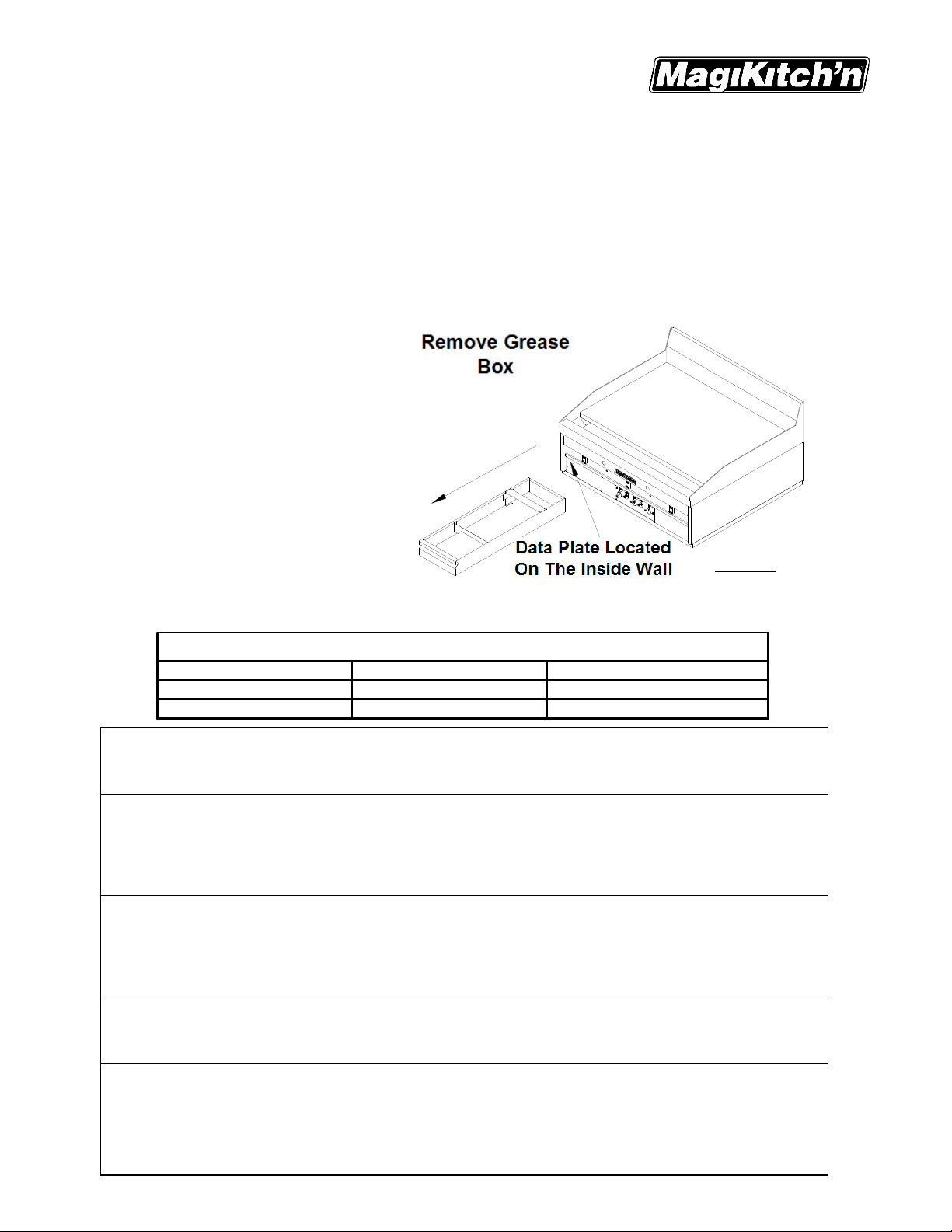
Locate the MagiKitch’n Model Number and Serial Number from the information plate on the inside wall,
see Figure 1. Write this information and the date the appliance was purchased on the front of this manual.
If you have completed the above
steps that are applicable to the appliance
you purchased, the appliance is now
ready to be installed. Although it may be
possible for you to install and set up your
new appliance, it is STRONGLY advised
that you have this done by qualified
service professionals. A qualified
professional will ensure that the
installation is safe and meets local
building and fire codes.
1.2. Electrical Connection(s)
It is advised that this appliance be
plugged into a wall receptacle that is
controlled by the ventilation control. This will prevent the appliance from being operated without the
ventilator on. A schematic is behind the front access panel. The power requirements are listed below.
Electrical Requirements
North America International
Input Voltage 120 Vac 50/60 Hz 220,230, or 240 Vac 50/60 Hz
Current/Control 0.22 Amps 0.11 Amps
CAUTION
Connecting the appliance to an electrical supply other than that indicated on the data pla te.
may damage the appliance and void the warranty.
WARNING
If the appliance is equipped with a power cord and it is damaged, it must be replaced by a
MagiKitch’n Authorized Service and Parts (ASAP) company technician, or a similarly qualified
person in order to avoid a hazard. A replacement, oil resistant cord must be provided by the
manufacturer.
WARNING
The electrical connection used by this appliance must comply with local codes. If there are no
local codes that apply, refer to the National Electrical Code (NEC), ANSI/NFPA 70 for
installation in the US. In Canada, refer to CSA Standard C22.2 and local codes. In all other
cases
refer to local and national codes and regulations.
Figure 1
WARNING
This equipment must be installed so that the plug is accessible unless other means for
disconnection from the power supply (e.g. a circuit breaker) is provided.
WARNING
If your appliance uses line current, it is equipped with an oil proof, electrical supply cord with a
three-prong safety plug. This is to protect operators from electrical shock hazard in the event
of an equipment malfunction. DO NOT cut or remove the grounding (third) prong from this
plug; it should be plugged into a properly grounded three-prong receptacle.
4
L25-055 Rev. 0 (05/12)
Page 5

Installation
MKG Series Gas Griddle
1.3. Installation Clearances
Your new MagiKitch’n Griddle needs clearance around it for proper operation. Adequate clearances allow
for servicing and proper burner operation. The clearances shown belo w a re for in stallation in combustible
and non-combustible construction. The appliance can be serviced from the front of the unit, however it
may need to be pulled away from the wall for access to the gas supply and electrical supply connections.
Ensure that all clearances stated on the Data plate and in the table below are strictly followed.
Location
Cabinet back 8.0 (20.4) 8.0 (20.4)
Cabinet Sides 2.0 (5.0) 0.0 (0.0)
1.4. Gas Connection(s)
Your gas appliance will give you peak performance when the gas supply line is of sufficient size to
provide the correct gas pressure. The gas line must be installed to meet the local building codes or
National Fuel Gas Code ANSI Z223.1 Latest Edition. In Canada, install the appliance in accordance
with CAN/CGA-B149.1 or .2 and local codes. In Australia, install the appliance in accordance with
AS/NZS 5601. Gas line sizing requirements can be determined by your local gas compa ny or, in
North America, by referring to the National Fuel Gas Code, Appendix C, Table C-4 (for natural gas)
and Table C-16 (for propane). The gas line needs to be large enough to supply the necessary am ount
of fuel to all appliances without losing pressure to any appliance. A properly sized and installed gas
line will deliver a supply pressure between 7.0” W.C. (17.4mbars, 1.74kPa) and 10.0”W.C.
(24.9mbars, 2.49kPa) natural gas or between 11.0”W.C. (27.4mbars, 2.74kPa) and 13.0 ” W.C.
(32.4mbars, 3.25kPa) for propane to all appliances connected to the supply line, operating
simultaneously at full demand. The pressure at the gas valve shall not exceed ½ PSI.
NEVER supply the appliance with a gas that is not indicated on the data plate. Supplying incorrect
gas will cause improper operation. Contact your Dealer for another gas type for the appliance.
Combustible Construction
Inches (Centimeters)
WARNING
Non-Combustible Construction
Inches (Centimeters)
1.4.1. Fuel Type(s)
Each appliance is equipped to work with one type of fuel. The type of fuel with which the appliance is
intended to operate is stamped or printed on the data plate, see Figure 1.
CAUTION
NEVER use an adapter to make a smaller gas supply line fit the appliance connection. This may
limit proper gas flow for optimum burner operation, resulting in poor performance.
1.4.2. Quick Disconnect Connection
In North America, gas appliances equipped with casters must be installed with connectors that comply with
the Standard for Connectors for Movable Gas Appliances, ANSI Z21.69.CSA 6.16 Latest Edition. This
connection should include a quick disconnect device that complies with the Standard for Quick Disconnect
Devices for Use With Gas Fuel Appliances ANSI Z21.41.CSA 6.9 Latest Edition. In Australia, an appliance
equipped with casters and a flexible gas line must be connected to the gas supply with a quick disconnect
device that complies with AS 4627 and a restraining cable. The restraining cable must not exceed 80% of
the length of the flexible gas line. The restraining device should be attached to the appliance at the back
panel.
1.4.3. Fuel Supply Line and Leak Pressure Testing
The fuel supply system must be tested before the appliance is used. If the fuel line is going to be tested at
a pressure greater than ½ PISG (3.45 kPa, 34.5 mbar), insure that that appliance is disconnected from
the fuel line. If the fuel line is to be tested at a pressure equal to or less than ½ PSIG (3.45 kPa, 34.5
mbar), the appliance can be connected during the test, but the unit’s gas valve must be shut. Test all gas
line connections for leaks with a solution of soap and water when pressure applied.
1.5. Ventilation And Fire Safety Systems
Your new gas appliance must have proper ventilation to function safely and properly. Exhaust gas
temperatures can reach as high as 1000°F (538 °C). Therefore, it is very important to install a fire safety
system. Your ventilation system should be designed to allow for easy cleaning. Frequent cleaning of the
ventilation system and the appliance will reduce the chances of fire. Table 1-2 provides a list of reference
documents that provide guidance on ventilation and fire safety systems. This table is not necessarily
complete. In North America, additional information can be obtained from CSA International, 8501 East
L25-055 Rev. 0 (05/12)
5
Page 6
Installation
MKG Series Gas Griddle
Pleasant Valley Rd., Cleveland, OH 44131. In Australia, the ventilation system must comply with AS/NZS
5601.1.
CAUTION
Excessive ventilation causes drafts, which will interfere with the operation of the appliance. Leave
at least 18 inches of open space between the flue opening and the intake of the exhaust hood.
CAUTION
Ensure that your ventilation system does not cause a down draft at the appliance’s flue opening.
Down drafts will not allow the appliance to exhaust properly and will cause overheating which
may cause permanent damage. Damage caused by down drafts will not be covered under
equipment warranty. NEVER allow anything to obstruct the flow of combustibles or ventilation
exiting the appliance flue.
1.6. Installation Setup
The installation of this appliance MUST conform to
local codes. In the absence of local codes in North
America, the installation must conform with the
National Fuel Gas Code, ANSI Z223.1/NFPA 54 or
the Natural Gas and Propane Installation Code
CSA B149.1 as applicable. In Australia, the
appliance must installed in compliance with
AS/NZS 5601 (current revision).
To Start uncrate appliance and locate installation
accessories.
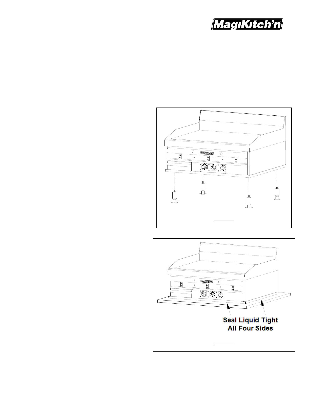
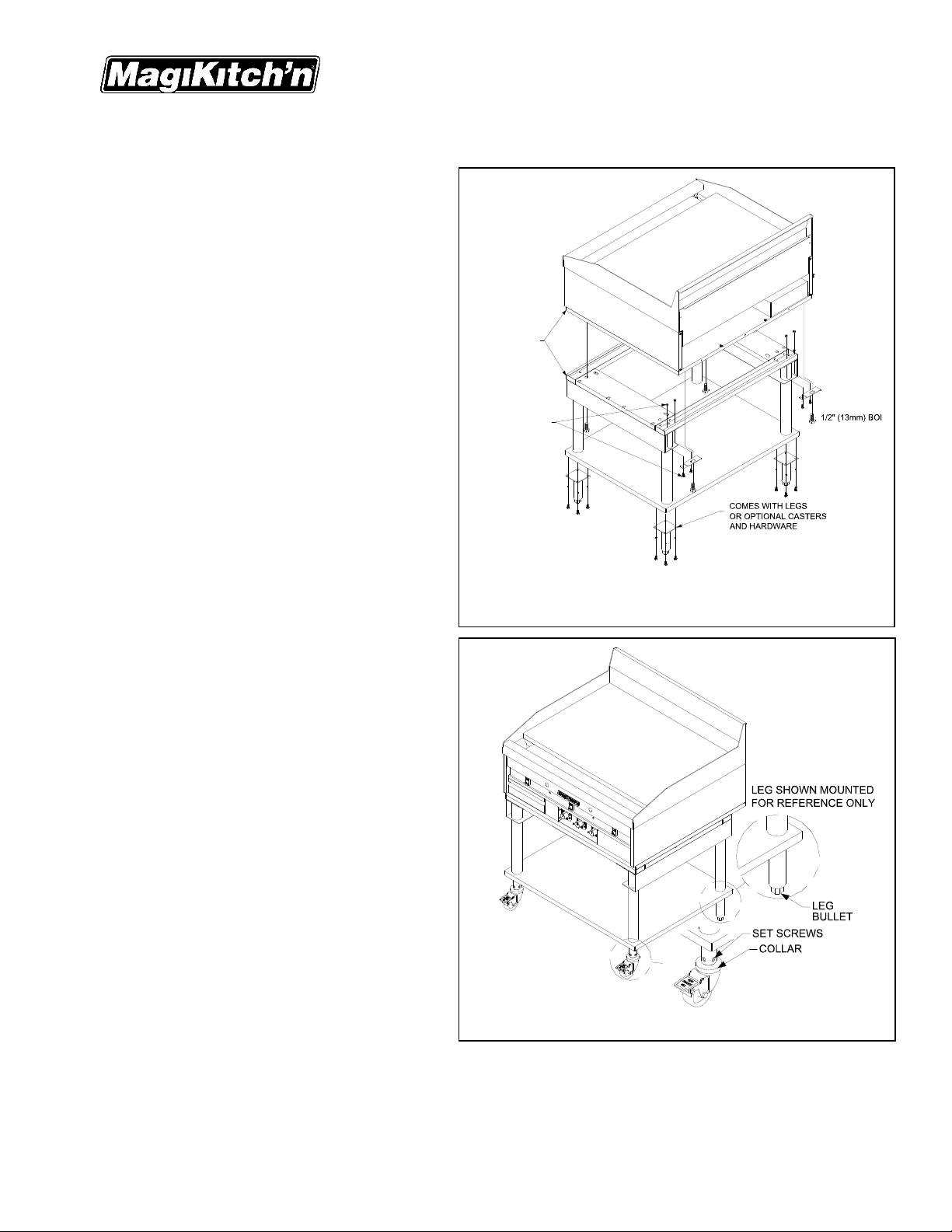
1.6.1. Counter Use With Legs
CAUTION
To prevent equipment damage, DO NOT tilt
your MagiKitch'n griddle on only two legs, or
on its sides.
(See Figure 2) A set of 4” (10.2cm) legs is
shipped with the appliance (unless appliance
was specifically ordered without legs). A
threaded insert for the leg bolt is located near
each corner of the bottom appliance. Raise the
appliance to allow legs to be screwed tightly into
inserts. The appliance can be leveled by
adjusting the feet at the bottom of the leg
assembly. This can be done by turning the foot
in or out to lower or raise each corner as
needed.
NOTICE
4" Legs should not to be used with the
Equipment Stand.
1.6.2. Counter Use Without Legs
See Figure 3) The appliance must be sealed to the
counter to comply with applicable sanitation
standards. A bead of silicone sealant,
approximately ½ inch (13 mm) wide, is to be
applied to the bottom of the unit approximately ¼”
(7 mm) in from the front, back and side edges. We
suggest Dow Corning ® 732 silicone ‘RTV’
adhesive sealant or equivalent. (See NSF Basic
Criteria C-2 for details).
WARNING
DO NOT alter or remove structural material
on the appliance to accommodate placement
under a ventilation hood.
Figure 2
Figure 3
6
L25-055 Rev. 0 (05/12)
Page 7
1.6.3. Equipment Stand
ATTENTION
Rear mounting brackets should be installed
to the Equipment Stand prior to placing
griddle on the stand.
IMPORTANT
Install the griddle so that the locking casters
are at the front of the unit. The casters
should be LOCKED before the unit is placed
into operation.
(See Figure 4). To mount the griddle to the
stand, locate joining kit supplied with stand. The
joining kit should include (2) rear mounting
brackets, and (4) 1/2" (13mm) mounting bolts.
To mount the griddle to the equipment perform
the steps on the following page:
IMPORTANT
The appliance must be level to perform
properly. Failure to level unit may result in
improper performance of the appliance.
MOUNT FLUSH
TO FRONT
NUTS & BOLTS
INCLUDED
WITH STAND
Installation
MKG Series Gas Griddle
REAR
BRACKET (2)
(SUPPLIED)
(SUPPLIED)
NOTICE
Larger models have 6 threaded receiving
holes, but require only the four 1/2" (13mm)
bolts on each corner to mount the griddle.
1. Remove (4) existing 1/4-20 nuts and bolts
from the rear corners of the equipment
stand.
2. Align the 2 bolt holes on the rear corners of
the stand with the 2 bolt holes on the rear
mounting brackets. Orient the brackets as
shown in Figure #4 on this page.
3. Install the provided rear mounting brackets
(2) to the rear corners by using the existing
1/4-20 hardware that were removed in step
1, tighten securely.
4. Carefully place the griddle on the equipment
stand.
5. Once the griddle is on the stand, position
the griddle on the stand so that the front
edge of the base is flush with the front of
the equipment stand. If the griddle is the
only appliance to be mounted on the stand,
then both sides of the griddle should be
flush with the sides of the equipment stand.
6. When positioned properly, the threaded
receiving holes in the griddle base should
be aligned with mating clearance holes at
the front of the equipment stand, and with
the clearance holes in the rear mounting
brackets. Install the provided 1/2" (13mm) bolts and tighten securely.
Figure 4
Figure 5
L25-055 Rev. 0 (05/12)
7
Page 8
Installation
MKG Series Gas Griddle
1.6.4. Leveling Instructions
NOTICE
Equipment stands are shipped from the factory with the legs or casters set to the minimum height
adjustment. Units should be leveled at time of installation, failure to do so could cause the griddle to
operate improperly.
1. Identify the corner of the stand that needs to be adjusted, remove the weight load from the corner to be
leveled.
2. Legs- using a wrench, or pliers turn the leg bullet, See Figure 5, CCW to raise the height of the equipment
stand. There is ½” (13mm) to ¾” (19mm) of adjustment.
Casters- Using a Flat Head screwdriver, loosen the set screws of the caster to be leveled, See Figure
5.Turn the collar of the caster CCW to raise the height of the equipment stand. There is ¾” (19mm) of
adjustment.
After leveling adjustment is complete, re-tighten set screws.
3. Check the levelness of the equipment, if necessary Repeat steps 1 and 2.
NOTICE
This appliance may only be installed with casters provided by the manufacturer. When installed with
casters in North America, a gas connection complying with ANSI Z21.69/CGA-6.16 and a quick disconnect
device complying with ANSI Z21.41/CAN 1-6.9. It must also be installed with a restraining device to guard
against putting any strain on the gas connections when the unit is moved. In Australia the quick
disconnect device must comply with AS4627. The restraining device must not exceed 80% of the length
of the flexible gas line.
1.7. Final Gas Connection
A properly installed gas supply system will deliver adequate pressure, between 7 and 8 inches w.c. (1.75- 2.0
kPa, 17.5-20.0 mbars) for natural gas, or 11 to 12 inches w.c. (2.7-3.0 kPa, 27.0-30.0 mbars) for propane to
all appliances connected to the line, operating at full demand.
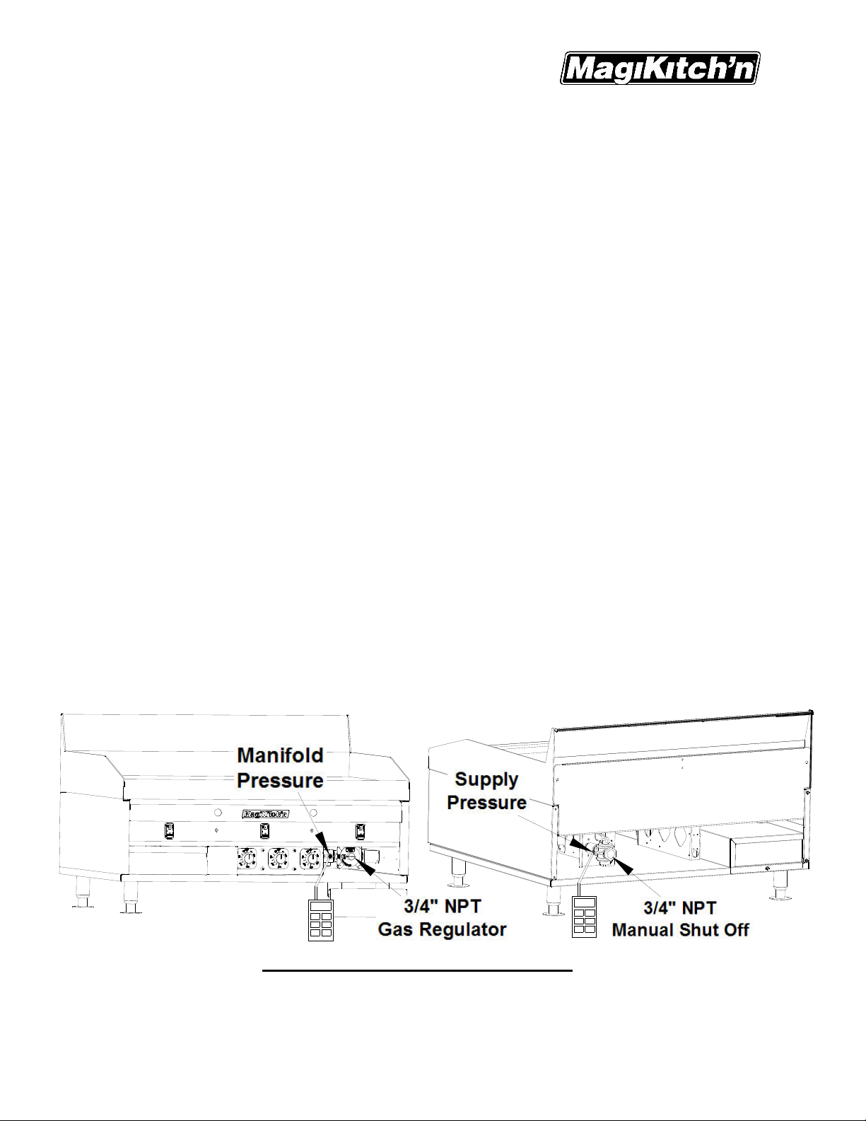
1.7.1. Regulator Assembly
An adequate gas supply is important for the appliance to operate properly. Undersized lines or lowpressures will restrict the volume of gas required for satisfactory performance. A steady supply
pressure between 7” and 8” w.c. (1.75-2.0 kPa, 17.5-20 mbars) for natural gas or 11” to 12” (2.7-3.0
kPa, 27-30 mbars) for propane gas is required. With all gas appliances operating simultaneously, the
manifold pressure on all gas appliances should not show any appreciable drop. Fluctuations of more
than 25% on natural and 10% on propane gas will create pilot problems and affect burner operating
characteristics. Contact your gas company for correct supply line sizes. After connection, a certified
gas service agent should check all newly installed equipment for correct gas pressure. The unit should
be connected ONLY to the type of gas for which it is equipped. Check the gas type on the Data plate;
see section 1.1 of this manual.
Figure 6, Matchless Ignition Regulator System
1. The gas input regulator for your new appliance has been installed at the factory, See Figures 6 & 6a
depending on the model of your appliance for the location of the regulator and the manual shut off
valve. Using a regulator other than the one supplied with the unit will void the warranty.
2. The manifold pressure must be maintained at the pressure marked on the Data plate. The manifold
pressure reading is taken at the 1/8” NPT coupling located behind the lower front panel next to the gas
8
L25-055 Rev. 0 (05/12)
Page 9

Installation
MKG Series Gas Griddle
regulator, see Figure 6 & 6a. To check the supply pressure to the appliance use the pressure test
point supplied on the manual shut off valve, also see Figure 6 & 6a.
3. Use pipe joint compound that is suitable for use with LP gas on all threaded connections.
4. Turn off all thermostats.
5. Turn on gas supply and check all connections for leaks using ONLY a leak checking fluid or soapy
water. NEVER use an open flame to check for gas leaks.
6. Provisions must be made for adequate air supply for both the appliance and room occupants.
7. Keep area in front of unit clear of obstructions that may block flow of combustion and/or ventilation air.
Figure 6a, Snap Action Regulator System
1.7.2. Gas Settings
Orifices are sized to provide proper gas flow to the rated BTU/hr for each model. Regulator pressure
must be measured and adjusted before the unit goes into service, following installation and when
operational performance is in question. The manifold and supply pressure readings are taken at the
pressure test points provided, see Figure 6 & 6a.
Gas Type BTU/hr(kW) per Burner Manifold Pressure (All Models)
Natural 15,000 (4.4) 4.0" WC (10.1cm) [10 mbar]
Propane 15,000 (4.4) 10.0" WC (25.4cm) [25 mbar]
WARNING
Ensure that the appliance can get enough air to keep the flame burning correctly. If the flame is
starved for air, it can give off a dangerous carbon monoxide gas. Carbon monoxide is a clear odorless
gas that can cause suffocation.
L25-055 Rev. 0 (05/12)
9
Page 10

Operations
MKG Series Gas Griddle
1.7.3. Gas Table
Applicable
Countries
Model
Fuel Type
AT, BG, CH, CZ, DK, EE, FI, GB,
GR, HU, IE, IT, LT, LV, NO, PL,
PT, RO, ES, SI, SK, SE, TR
LU
FR
BE G20/G25
MK24 17.6
Nat
DE G20/G25
NL G25
BG, CH, CY, CZ, FR, DE, GB,
GR, HU, IE, IT, LU, MT, NL, PL,
LP G31
PT, RO, ES, SI, SK, TR
AT, BG, CH, CZ, DK, EE, FI, GB,
GR, HU, IE, IT, LT, LV, NO, PL,
PT, RO, ES, SI, SK, SE, TR
LU
FR
BE G20/G25
MKG36 26.4
Nat
DE G20/G25
NL G25
BG, CH, CY, CZ, FR, DE, GB,
GR, HU, IE, IT, LU, MT, NL, PL,
LP G31
PT, RO, ES, SI, SK, TR
AT, BG, CH, CZ, DK, EE, FI, GB,
GR, HU, IE, IT, LT, LV, NO, PL,
PT, RO, ES, SI, SK, SE, TR
LU
FR
BE G20/G25
MKG48 35.1
Nat
DE G20/G25
NL G25
BG, CH, CY, CZ, FR, DE, GB,
GR, HU, IE, IT, LU, MT, NL, PL,
LP G31
PT, RO, ES, SI, SK, TR
AT, BG, CH, CZ, DK, EE, FI, GB,
GR, HU, IE, IT, LT, LV, NO, PL,
PT, RO, ES, SI, SK, SE, TR
LU
FR
BE G20/G25
MKG60 43.9
Nat
DE G20/G25
NL G25
BG, CH, CY, CZ, FR, DE, GB,
GR, HU, IE, IT, LU, MT, NL, PL,
LP G31
PT, RO, ES, SI, SK, TR
AT, BG, CH, CZ, DK, EE, FI, GB,
GR, HU, IE, IT, LT, LV, NO, PL,
PT, RO, ES, SI, SK, SE, TR
LU
FR
BE G20/G25
MKG72 52.7
Nat
DE G20/G25
NL G25
BG, CH, CY, CZ, FR, DE, GB,
GR, HU, IE, IT, LU, MT, NL, PL,
LP G31
PT, RO, ES, SI, SK, TR
Gas
G20
G20
G20
G20
G20
Appliance
I
I
I
2ESI
I
2E+
I
2ELL
I
I
I
I
I
2ESI
I
2E+
I
2ELL
I
I
I
I
I
2ESI
I
2E+
I
2ELL
I
I
I
I
I
2ESI
I
2E+
I
2ELL
I
I
I
I
I
2ESI
I
2E+
I
2ELL
I
I
2H
2E
2L
3P
2H
2E
2L
3P
2H
2E
2L
3P
2H
2E
2L
3P
2H
2E
2L
3P
Category
Gross
Input (kW)
Net
Input (kW)
Supply
Pressure (mbar)
Burner
Pressure (mbar)
Burner
Orifice
Pilot
20
15.8
20/25
1.85 mm YES 1.7
10
N22
1.85/2.1
mm
25 2.1 mm YES 2.0
16.2 50/37 25.4 1.10 mm LP16 YES 0.7
20
23.8 10
20/25
1.85 mm
N22
1.85/2.1
mm
25 2.1 mm YES 2.9
24.3 50/37 25.4 1.10 mm LP16 YES 1.0
20
31.6 10 N22
20/25
1.85/2.1
mm
25 2.1 mm YES 3.9
32.3 50/37 25.4 1.10 mm LP16 YES 1.3
10
1.85 mm
N22
1.85/2.1
mm
20
39.5
20/25
25 2.1 mm YES 4.9
40.4 50/37 25.4 1.10 mm LP16 YES 1.7
20 9 1.85 mm
47.5
20/25 9/10
1.85/2.1
mm
N22
25 10 2.1 mm YES 5.8
48.5 50/37 25.4 1.10 mm LP16 YES 2.0
Orifice (code)
NO
YES
YES
NO
YES
YES1.85 mm
NO
YES
YES 4.2
NO
YES
YES
NO
YES
Governor
Nominal Gas
1.7/2.0
2.5
2.5/2.9
3.3
3.3/3.9
4.2/4.9
5.0
5.0/5.8
Rate (m3/hr)
10
L25-055 Rev. 0 (05/12)
Page 11

Operations
MKG Series Gas Griddle
2. Operation
Ensure that a proper installation has been performed on the appliance and that all warnings, cautions, and
notices contained in this manual have been read, understood and adhered to before proce eding.
2.1. Lighting Instructions
2.1.1. Snap-Action Thermostat Appliances
1. Turn all thermostat knobs to the “OFF”
position.
2. Open front door of the griddle, turn the
manual gas shut off valve to the “ON”
position, see Figure 6.
3. Press and hold the left or right RED
pilot button, see detail Method A at right,
and light the left or right pilot by depressing
the Piezo ignition control, look through the
pilot hole to see the pilot ignites. With pilot
burning, keep the RED pilot knob
depressed for 45 seconds or until pilot
remains lit automatically. If the Piezo
ignition control does not light the pilot(s), a
flame source can be used to light the
pilot(s) through the pilot holes provided in the front panel of the appliance.
4. Repeat steps 1,2, and 3 for all remaining pilots.
5. Operate thermostats by turning knobs clockwise to the desired temperature and insure that burners light
properly by looking through the pilot holes provided in the front panel.
LEFT PIEZO IGNITOR
PILOT HOLES
LEFT PILOT BUTTON RIGHT PILOT BUTTON
RIGHT PIEZO IGNITOR
2.1.2. Solid State and Electric Thermostat Appliance
1. Turn all thermostat knobs to the “OFF” position, or the lowest possible temperature setting.
2. Turn the Manual gas shut off valve to the "ON" position, this valve is located at the rear of the unit, see
Figure 6a. To open the valve to allow gas flow the handle should be in line with the manual shut off valve.
3. Turn the RED "I/O" switch to the “ I ” (ON) position for all desired Thermostats to be operated, See Figure
7. When the Pilot ready (Yellow) light illuminates, the pilot(s) are ready to operate the main burners.
4. Repeat steps 1,2, and 3 for all thermostat controls to be operated.
5. Operate thermostats by turning knobs clockwise to the desired temperature and insure that burners light
properly by looking through the pilot viewports provided in the front panel. The RED "I/O" switch will
illuminate when the thermostat calls for heat.
Figure 7
L25-055 Rev. 0 (05/12)
11
Page 12

Operations
MKG Series Gas Griddle
CAUTION
If Pilot Ready light(s) does not illuminate, Turn all Thermostat "I/O" switches for that pilot to
“O”(OFF), wait five minutes before attempting to re-light.
WARNING
If the gas supply and/or the electrical power is interrupted, or if pilot(s) extinguish, turn the
thermostat knobs and the gas shut off valve to the "OFF" position and wait five (5) minutes
before attempting to re-light the pilot. Do not attempt to operate this appliance during a power
failure.
2.2. Initial Startup
NOTICE
New griddles should be carefully tempered and cared for in order to avoid possible damage.
Wipe the griddle surface clean. A mild soapy water solution may be used to clean the surface, be sure to rinse
cooking surface thoroughly with fresh water to eliminate any soap residue. It is also important to wipe the
griddle surface and surrounding areas to dry up any standing water. Never allow water on a hot griddle
surface.
Seasoning is not required on a Chrome Plated Cooking surface, but the following procedure may be
performed to improve the non-stick qualities of the chrome plated cooking surface.
2.2.1. Griddle Surface Seasoning
1. To season the griddle, Light all pilots and turn all the thermostat controls to 200°F, (93°C). As the
unit heats up to 200°F, (93°C), apply a light film of cooking oil or beef suet over the entire cooking
surface, wiping off any excess build up. This step may be repeated as necessary to apply an even
coating on the griddle surface. Seasoning will help create and maintain a non-stick cooking
surface on your griddle.
2. Allow the seasoned surface to idle for one hour at 200°F, (93°C), Then set the thermostats to your
desired cooking temperature, once your griddle surface has reached temperature, apply another
coating of seasoning oil, wiping off any excess that may cause build up.
2.2.2. Surface Temperature Check
1. If available, place grill surface thermometer over each thermostat sensing probe 12", (30.5cm),
from the front edge of the griddle surface, See Figure 8 below. The sensing probes are located in
line with the thermostat knobs on snap action models, or the ON/OFF switch(s) on matchless
ignition models. Align your measuring device with the respective location on your appliance and
monitor the temperature at all the controls that are to be adjusted.
2. Heat the griddle up to the desired cooking temperature; check the surface temperature reading on
the grill thermometer. If necessary, adjust the thermostats that control any area of the surface that
are not within ± 15°F (± 8.3°C) of the thermostat setting. The procedure for adjusting the
thermostats is in Section 3.
2.2.3. Shutdown Procedure
1. Turn thermostat knobs to the
“OFF” position, or the lowest
possible temperature setting.
2. On matchless ignition models turn
“I/O” Switch to “O” position.
3. Close manual gas valve shut off.
4. Allow griddle surface to cool
normally.
12
Figure 8
L25-055 Rev. 0 (05/12)
Page 13

Calibration
MKG Series Gas Griddle
3. Thermostat Calibration Section
Each control typically operates a pair of burners with a Snap action, Electric or Solid State. The controls were
set at the factory. However, if the griddle’s surface temperature varies greatly from the setting on the
thermostat knob, adjust the thermostat using the following procedure:
3.1. Snap Action and Electric Thermostat
1 Light pilots as described in section(s) 2.1.1 and
2.1.2.
2 Turn all the control knobs to the desired
temperature setting.
THERMOSTAT ADJUSTMENT SCREW
TURN CW TO DECREASE TEMPERATURE
TURN CCW TO INCREASE TEMPERATURE
3 Wait 30 minutes (or 1 hour if griddle was cold)
for surface to stabilize.
4 Place a reliable Griddle surface thermometer,
or
THERMOSTAT KNOB
REMOVED, SNAP ACTION
THERMOSTAT STEM
test instrument thermocouple, able to register
300°F (149°C), in the location above the
thermostat being calibrated as described in
section 2.2.2. Check the temperature every 5
ELECTRIC THERMOSTATS SHOWN FOR REFERENCE
minutes until the temperature stabilizes and
does not change by more than 30°F (16.5°C) over a 15 minute span. Figure 9
5 If the average temperature over any burner set is not within +/-15°F (8.3°C) of the knob setting, adjust the
corresponding thermostat. This is done by removing the knob, holding the thermostat knob stem, see
Figure 9, (do not allow the stem to turn or the temperature setting will not be accurate), then turn the
adjustment screw located within the center of the stem in small increments. Turn this screw counter
clockwise to increase the temperature, and clockwise to decrease the temperature.
6 Check the temperature after 15 minutes and repeat adjustment as needed until the correct temperature is
indication on the measuring instrument.
NOTE:
Hold the knob firmly when loosening or tightening the 5/16” (8mm) locknut that holds the knob onto
the thermostat shaft to keep from changing temperature settings.
3.2. Solid State Thermostat
1 Light pilots as in section 2.1.1.
2 Set all the thermostat control knobs to the desired cooking temperatures.
3 Wait 30 minutes (or 1 hour if griddle was cold) for surface temperature to stabilize.
4 Place a reliable Grill surface thermometer,
or test instrument thermocouple, (able to register 550°F
(288°C)), In the location above the thermostat being calibrated described in section 2.2.2.
5 Check the temperature at each location every 5 minutes, and repeat until the temperature stabilizes and
does not change by more than 20°F (11.0°C) over a 15 minute time period. You will need to remember the
average temperature for the following steps.
6 If the thermostat is not operating within 10°F (5.5°C) of the temperature set point, you may need to adjust
the control.
7 To adjust the control, carefully remove the cap on the thermostat knob, See Figure 9a, set cap aside.
8 While holding the knob, loosen the 5/16" (8mm) nut on the thermostat shaft, (DO NOT REMOVE).
9 Once the knob is loosened from the thermostat
shaft, rotate the knob so the white indicator line
of the knob is aligned with the actual
temperature that you monitored in step 5.
10 Re-tighten the 5/16" (8mm) nut while holding
the knob in position, (do not allow the stem to
turn or the temperature setting will not be
accurate).
11 Set the control to the desired temperature and
monitor as in step 5, readjust temperature
control as needed until desired temperature is
achieved.
12 Make sure the control knob is secured, replace
THIS CAP SNAPS
ON AND OFF
0
0
3
0
4
1
0
0
5
2
2
1
0
0
0
1
0
2
8
0
1
5
0
ALIGNED WITH ACTUAL TEMP.
350
4
1
8
0
0
0
2
6
0
1
0
0
2
2
4
0
5
0
2
4
0
5
2
6
0
0
0
0
8
2
0
5
°
C
5
°F
ROTATE KNOB UNTIL
TEMP. INDICATOR IS
5/16" NUT
350
4
1
8
0
0
0
0
2
6
0
0
1
0
0
3
0
4
1
0
0
5
2
2
1
0
0
0
1
0
2
8
0
1
5
0
2
2
4
0
5
0
2
4
0
CAP LINE
5
2
6
0
0
0
0
8
2
0
5
°
C
5
°F
cap.
Figure 9a
L25-055 Rev. 0 (05/12)
13
Page 14

Basic Operation
MKG Series Gas Griddle
4. Basic Operation
4.1. Operational Helpful Hints
1. Each thermostat controls 12" (30.5cm) of griddle surface, whenever possible, use the leftmost or
rightmost thermostats for the lowest cooking temperatures. The adjacent thermostats set at higher
temperatures will effect centrally located thermostats.
2. For quicker thermostat response during heavy loading of the griddle, load product directly over the
thermostat sensing probe. For slow periods load product to one side of the sensing probe to limit
possible overheating of unused griddle surface.
3. Whenever possible, rotate the location of where product is cooked, this will keep the entire 12"
(30.5cm) of the controlled area at a more even temperature.
4. If any product sticking occurs, apply a thin coat of cooking oil to the surface before loading product.
5. When using spatulas or scrapers, it is Highly Recommended that the corners of the tools never strike
the griddle surface with any force. This could cause damage to the surface that could collect food
particles, and make it difficult to clean.
4.2. Suggested Cooking Times And Temperatures
NOTICE
The times and temperatures in this chart are suggestions only. Your experience with your own menu
items will be your best guide to achieving the best food product.
Product Temperature Time
Breakfast Items
Pancakes 375°F (191°C) 2 Minutes
French Toast 400°F (204°F) 4-5 Minutes
*Breakfast Potatoes 375°F-400°F (19 1°C-204°C) 15-20 Minutes
Eggs
Scrambled 300°F (149°C) 3-4 Minutes
Sunny Side Up 225°F-300°F (107°C-149°C) 3-4 Minutes
Over Easy 250°F-300°F (121°C-149°C) 2-3 Minutes
Over Hard 225°F-300°F (107°C-149°C) 3-4 Minutes
Breakfast Meats
Sausage, Link and Patty 350°F (177°C) 3 Minutes
Bacon 350°F (177°C) 2-3 Minutes
Canadian Bacon 350°F (177°C) 2-3 Minutes
Ham Steaks 375°F (191°C) 3-4 Minutes
Broiled Ham 375°F (191°C) 2 Minutes
Ham, Pre-Cooked 375°F (191°C) 2 Minutes
Fish
Salmon 350°F (177°C) 6-8 Minutes
Hamburgers
2 Patties per Lb. 350°F (177°C) 6-8 Minutes
4 Patties per Lb. 350°F (177°C) 4-6 Minutes
6 Patties per Lb. 350°F (177°C) 3-4 Minutes
Steaks, Etc.
1/2"-3/4" Thick, Medium 375°F (191°C) 5-7 Minutes
3/4"-1" Thick, Medium 375°F (191°C) 8-10 M inutes
Beef Tenderloin 400°F (204°F) 3-4 Minutes
Sandwiches, Etc.
Grilled Cheese 375°F (191°C) 3-4 Minutes
Hot Dogs 325°F (163°F) 2-3 Minutes
*Based on cubed potatoes brought to a boil then cooled prior to finishing on griddle. To reduce
burning and sticking of the potatoes, coat the griddle surface with vegetable oil and turn potatoes
frequently.
14
L25-055 Rev. 0 (05/12)
Page 15

Cleaning & Maintenance
MKG Series Gas Griddle
5. Cleaning & Maintenance Section
5.1. Griddle Surface Cleaning, During Operation Hours
1. Keep the griddle surface clean to prevent sticking and poor food product quality.
2. Scrape the griddle plate regularly through out the day with a scraper intended for your type of griddle
surfaces to remove all surface grease and food debris.
NOTICE
Do not use Grill Bricks, Grill Screens, or any other type of abrasive material on your
MagiKitch'n Chrome Griddle Surface. USING ABRASIVE MATERIALS WILL VOID YOUR WARRANTY.
3. Clean and wipe out grease chutes.
4. Wipe down the exterior with a clean rag or towel to keep grease and food debris from building up on
the stainless steel exterior, thermostat controls and switches.
5. At the end of the daily operation hours a degreaser, or stainless steel cleaner can be used to wipe
down all the exterior surfaces. Care should be taken to rinse any cleaning solvent residue from any
surfaces that may come in contact with food.
6. Remove and empty grease box(es) of any and all debris, also wipe down the inside of the grease box
compartment for food particles that may have come free from the grease box.
NOTICE
The grease box is designed to contain grease run off from the griddle surface. The grease box should
NEVER be allowed to overfill, and should be emptied accordingly, and grease disposed of properly.
5.2. Griddle Surface Cleaning, End Of Shift
NOTICE
Wear protective gloves and clothing when cleaning the appliance, HOT Surfaces
may cause personal injury.
5.2.1. Plain Steel Cooking Surface
1. Scrape griddle surface completely with a scraper to remove grease and food debris.
2. Use a grill brick or grill screen to clean any heavy build up of carbon from the griddle surface.
Never use steel wool pads, small fibers may be left behind on the cooking surface.
3. When griddle surface is cool, Clean the cooking surface with a solution of water and Magi
Kleans'r, or similar type non-abrasive, non-caustic cleaners that are approved for stainless
steel.
4. When the cooking surface is cleaned of all foreign debris, rinse all surfaces completely with
clean water and wipe dry with a clean towel.
5. It may be necessary to season the grill again after this cleaning.
5.2.2. Chrome Plated Cooking Surface
1. Scrape griddle surface completely with supplied scraper to remove grease and food debris.
NOTICE
Do not use Grill Bricks, Grill Screens, or any other type of abrasive material on your
MagiKitch'n Chrome Griddle Surface. USING ABRASIVE MATERIALS WILL VOID YOUR WARRANTY.
2. When griddle surface is cool, Scrub the Chrome surface with the supplied palmetto cleaning
brush and cool water.
3. Shine the Chrome griddle cooking surface with Magi Kleans'r, water and a soft cloth.
4. Rinse with clean water and wipe away any residue with a dry cloth.
5.3. Monthly Maintenance
NOTICE
Regular maintenance of your MagiKitch'n griddle is Recommended to keep the appliance operating
properly.
5.3.1. Monthly Preventative Maintenance
Food debris and grease can buildup in and around the griddle . Performing the monthly preventative
maintenance steps below will keep your equipment safe and at peak performance. If you are
producing high quantities of grilled foods, it may be necessary to clean these components more then
once a month
Use a grill surface thermometer to make sure thermostats are operating properly.
Visually check that the pilot(s) flame(s) are strong and light the main burners properly.
Visually check the appearance of the main burners, all burners should have a nice blue flame.
L25-055 Rev. 0 (05/12)
15
Page 16

Cleaning & Maintenance
MKG Series Gas Griddle
Make sure that all gas connections have not been tampered with or damaged, check for leaks with
a soapy water solution. Never use an open flame to check for leaks.
Check to see that the flue exhaust area has no food debris, or blocked in any way. Never allow the
flue to become excessively dirty. The flue being free of obstruction is imperative to proper burner
operation.
Check to see that the ventilation hood and make up air systems are working properly. Any make
up air system should not be directed as to impede the flow of combustion air to the griddle, or flue
exhaust from the griddle.
Inspect griddle surface for any visible damage.
Inspect exterior cabinet for damage, loose parts, or sharp edges.
Check the function of all controls, lights, and switches.
5.4. Annual/Periodic Preventative Maintenance and Inspection
This section should ONLY be performed by a qualified service technician as part of a regular kitchen
maintenance program. This inspection should take place a minimum of once a year by an Authorized
Service Technician recommended by MagiKitch’n. It may be necessary perform this inspection more then
once a year.
5.4.1. Safety Evaluation
Check all gas connections, and verify that the griddle retention/lanyard system is in place.
Check for food debris and grease migration in and around the cabinet of the appliance.
Check legs/casters, and ensure all nuts and bolts are secured. (If Equipped)
Check the power cord and plug.
Check all exposed wiring connections, switches and indicator lights.
5.4.2. Mechanical Inspection
Check griddle surface for damage, rust, and any cracks in the chrome plating if applicable.
Check grease box for leaks.
Check for grease and water migration, clean as necessary.
Check ventilation hood drain cup and filters, clean as necessary.
Check flue for foreign debris and hood down draft currents.
Check for loose parts.
Check for missing parts and fasteners, replace as necessary.
5.4.3. Systems Operation Inspection
Check incoming gas pressure when all gas appliances are operating.
Check burner manifold gas pressure, adjust as necessary to Data plate information.
Check Ignition system and pilot flame, clean and adjust as necessary.
Matchless ignition units inspect spark gap, and spark electrode for damage.
Check and clean vent opening on manual shut off valve.
Check main gas valves for mechanical and electrical functionality.
Check all wire terminations, check for broken, or frayed wires.
Check temperature calibration.
Check thermostat operation and features for proper operation.
Verify all components are in good physical condition.
Ensure that all components are clean, and do not have any grease or water damage.
5.5. Ventilation Hood
Proper ventilation hood operation is very important for the correct operation of this appliance and the
safety of personnel. The ventilation hood should be inspected at the time of installation of this appliance to
insure that it will operate properly in conjunction with the appliance. A regular schedule of examination, in
accordance with ANSI/NFPA 96 latest edition and/or local codes must be followed.
16
L25-055 Rev. 0 (05/12)
Page 17

Trouble Shooting
MKG Series Gas Griddle
5.6. Trouble Shooting Charts
The following charts may help to eliminate any basic operational problems that you may be experiencing
with your appliance. Locate the problem on the left side of the chart, and cross-reference with the possible
cause. Once the problem has been identified take the appropriate action to rectify the problem.
5.6.1. Cooking Performance
If you are having poor cooking performance, or any inconsistencies in product quality, please refer to
the following chart for help.
Possible Cause
Heat
Set Too
High
Excessive
Smoke From
Fat
Product
Sticking
P
r
o
b
e
m
Product Edges
Burning
Product Centers
Underdone
Greasy Or
Un-desirable
Flavor
Grease Build Up
On Griddle
Surface
XX
XXX
XXX
XX
XX X
Moisture
In Food
Turning
To Steam
Griddle
Surface
Dirty Or
Un-Seasoned
Cooking Times
Too Short
Product Shelf
Life Expired
Improperly
Stored
Product
Excessive Oil
Or Grease
On Griddle
Surface
Heat Set Too
Low
XX X
5.6.2. Operating Performance
The following chart may help to diagnose any operational issue you may be experiencing with your appliance.
Some issues may REQUIRE that a qualified service technician perform the repairs. If a qualified service
technician is required, please contact the factory.
Pilot(s)
Will Not Light
Pilot Ready Light Will Not
P
r
o
Power Switch Will Not Illuminate
b
l
e
m
Griddle Stays Hot Or Overheats
Illuminate
Griddle Will Not Heat Up
Inconsistent Surface
Temperatures
All parts and service for your MagiKitch'n griddle should be ordered and installed by a MagiKitch'n
Authorized Service and Parts (ASAP) dealer. Failure to do so might result in the warranty being voided.
Possible Cause
Manual Gas
Valve Or
Gas Supply
Turned Off/
Disconnected
Unit Not
Plugged In
Faulty Ignition
Module Or
Flame Sense
Circuit
Power Switch(s)
Off / Faulty
Control
Transformer
Thermostats
Turned To
"Off"
Low Gas
Pressure
Thermostats
Not Calibrated
Thermostat Or
Gas Valve
Failure
Faulty
Lamp/Switch
XXX X X X
XXX X X X
XXXXX
XX XX
XX X
XX
NOTICE
L25-055 Rev. 0 (05/12)
17
Page 18

Accessories
MKG Series Gas Griddle
6. Accessories
6.1. Standard
All plain steel and chrome plated griddles are shipped with a set of 4” (10cm) adjustable legs. The
appliance also comes equipped from the factory with a manual gas shutoff valve, and the specified
gas regulator for the model and gas type purchased.
Each MKG Chrome surfaced griddle is equipped with a Chrome Kit which includes a cleaning brush,
cleaning powder, spatula, scraper, and scraper blade replacements. See the table below for Re-Order
Part Nos.
Chrome GriddleAccessories
Magi Kleans'r Part No. 9825-1525101
Palmetto Brush Part No. 9825-1524901
Spatula, (Chrome Surface) Part No. 9825-1525001
Scraper, (W/ Blade and Cover Part No. 9825-1528001
Replacement Blades Part No. 9825-1528002
Using MagiKitch'n chrome griddle accessories are
important to maintaining the life of the griddle's chrome
surface
6.2. Optional
To order accessories for your griddle, call your local MagiKitch’n dealer for prices and availability.
The list of available accessories for your new appliance will give you the flexibility to customize your
griddle to the best fit for your operational requirements.
This section will show you a variety of front and rear work shelves, cutting boards, equipment stands, and
other accessories to provide you with an efficient working appliance.
6.2.1. Service Shelves, Front
Shelf Model MKG24 MKG36 MKG48 MKG60 MKG72
8" (20.3cm) Service Shelf, W/O Towel Bar 5125-1511601-C 5125-1511602-C 5125-1511603-C 5125-1511610-C 5125-1511611-C
*10" (25.4cm) Service Shelf, W/O Towel Bar 5125-1511604-C 5125-1511605-C 5125-1511606-C 5125-1511612-C 5125-1511613-C
*12" (30.5cm) Service Shelf, W/O Towel Bar 5125-1511607-C 5125-1511608-C 5125-1511609-C 5125-1511614-C 5125-1511615-C
8" (20.3cm) Service Shelf, W/ Towel Bar 5125-1511701-C 5125-1511702-C 5125-1511703-C 5125-1511710-C 5125-1511711-C
*10" (25.4cm) Service Shelf, W/ Towel Bar 5125-1511704-C 5125-1511705-C 5125-1511706-C 5125-1511712-C 5125-1511713-C
*12" (30.5cm) Service Shelf, W/ Towel Bar 5125-1511707-C 5125-1511708-C 5125-1511709-C 5125-1511714-C 5125-1511715-C
Towel Bar Only 5125-1511801-C 5125-1511802-C 5125-1511803-C 5125-151804-C 5125-1511805-C
* 10” and 12” service shelves are also available with pan cutouts. Consult factory for sizes and
availability.
18
L25-055 Rev. 0 (05/12)
Page 19

TOWEL BAR ONLY
CUTTING BOARDS ARE AVAILABLE ON
Accessories
MKG Series Gas Griddle
WORKSHELVES WITH AND
WITHOUT TOWEL BARS
PAN CUTOUTS AND
LARGER WORKSHELVES
6.2.2. Cutting Boards
Size Part No.
8" X 12" (20.3 cm X 30.5 cm) Cutting Board 1604-0643600-C
8" X 12" (20.3 cm X 61.0 cm) Cutting Board 1604-0643700-C
8" X 12" (20.3 cm X 122.0 cm) Cutting Board 1604-0643800-C
8" X 12" (20.3 cm X 183.0 cm) Cutting Board 1604-0643900-C
Other sizes are available, consult factory for size, price, and availability.
L25-055 Rev. 0 (05/12)
19
Page 20

Accessories
MKG Series Gas Griddle
6.2.3. Warming Shelves, Rear
Shelf Model Part No.
C/A, Shelf Rear MKG24 5225-1535701-C
C/A, Shelf Rear MKG36 5225-1535702-C
C/A, Shelf Rear MKG48 5225-1535703-C
C/A, Shelf Rear MKG60 5225-1535704-C
C/A, Shelf Rear MKG72 5225-1535705-C
Shelf Kits can be attached to existing models. The Stainless Steel shelf is removable from the shelf
framework for easier cleaning if necessary.
REMOVABLE SHELF
20
L25-055 Rev. 0 (05/12)
EXISTING BOLTS
ON APPLIANCE
Page 21

Accessories
MKG Series Gas Griddle
6.2.4. Equipment Stands
Equipment stands can be ordered with legs or casters (stands with casters shipped after May 2006 are
equipped with adjustable casters).
NOTE:
It should also be noted that when ordering an equipment stand for your MKG appliance, you will also
need to order and MKG Joining Kit, Part No. 7225-1512101.
Equipment Stand Model Part No.
MKG24, W/ Legs 5225-1512001-C
MKG24, W/ Casters 5225-1512002-C
MKG36, W/ Legs 5225-1512005-C
MKG36, W/ Casters 5225-1512006-C
MKG48, W/ Legs 5225-1512007-C
MKG48, W/ Casters 5225-1512008-C
MKG60, W/ Legs 5225-1512009-C
MKG60, W/ Casters 5225-1512010-C
MKG72, W/ Legs 5225-1512011-C
MKG72, W/ Casters 5225-1512012-C
Equipment stands may be used to hold multiple MKG Griddles. They are also compatible with
MagiKitch’n Series 600 APM Charbroilers.
L25-055 Rev. 0 (05/12)
21
Page 22

Accessories
MKG Series Gas Griddle
6.2.5. Miscellaneous
Your appliance can also be used with the following miscellaneous accessories so you can customize
your operation to your specific demands.. The wall spacers listed below insure that you cannot push
the appliance too close to the rear wall. The Utensil box gives you a handy location to store your
cooking tools. The Utensil box does not interfere with any controls, and can be moved from one end of
the griddle to the other without the use of tools.
Accessory Part No.
6" (15.2 cm) Wall Spacer, LH MKG 5425-1526703-C
Utensil Box, MKG 9825-1532501-C
Utensil Box, MKG Towel Bar Only 9825-1532502-C
22
L25-055 Rev. 0 (05/12)
Page 23

Page 24

In the event of problems with or questions
about your order, please contact the
MagiKitch’n factory at:
PH- (603) 225-6684 World Wide
Website- www.magikitchn.com
MAILING ADDRESS – P.O. BOX 501, CONCORD, NH 03302-0501
SHIPPING ADDRESS – 10 FERRY ST., CONCORD, NH 03301
L25-055 Rev. 0 (05/12)
In the event of problems with or questions
about your equipment, please contact the
MagiKitch’n Authorized Service and Parts
representative (ASAP) covering your area,
or contact Pitco at the numbers
left.
listed to the
 Loading...