

Page 1
GAS GRIDDLE
INSTALLATION & OPERATION
MANUAL
MKG24, MKG36, MKG48, MKG60 & MKG72
Built After June 1, 2003
MAILING - P.O. BOX 501, CONCORD, NH 03302-0501
SHIPPING - 10 FERRY ST. CONCORD, NH 03301
TEL: 800-258-3708 • 603-225-6684 • FAX: 603-225-8497
www.magikitchn.com
L25-050 Rev. 0
Page 2
MKG SERIES GAS GRIDDLE INSTALLATION & OPERATION
THIS MANUAL MUST BE RETAINED FOR FUTURE REFERENCE
FOR YOUR SAFETY
DO NOT store or use gasoline or other flammable vapors or liquids in the vicinity of
this or any other appliance.
WARNING
Improper installation, alteration, service or maintenance can cause property damage,
injury or death. Read the installation, operating and maintenance instructions
thoroughly before installing or servicing this equipment.
TO THE PURCHASER
Post in a prominent location the
instructions to be followed in the event that
an operator smells gas. Obtain this
information from your local gas supplier.
WARNING
There is an open flame inside this
appliance. The unit may get hot enough to
set nearby materials on fire. Keep the area
around the appliance free from
combustibles.
WARNING
DO NOT supply the appliance with a gas
that is not indicated on the data plate. If
you need to convert the appliance to
another type of fuel, contact your dealer.
WARNING
DO NOT use an open flame to check for
gas leaks!
WARNING
If gas flow to appliance is interrupted, or pilots
extinguish, wait 5 minutes before attempting to
relight the pilot to allow any residual gas in
appliance to dissipate.
WARNING
Ensure that the appliance can get enough air to
keep the flame burning correctly. If the flame is
starved for air, it can give off a dangerous carbon
monoxide gas. `Carbon monoxide is a clear
odorless gas that can cause suffocation.
Models with electric controls are equipped with
an oil proof electrical supply cord, with a threeprong safety plug. This is to protect operators
from electrical shock hazard in the event of an
equipment malfunction. DO NOT cut or remove
the grounding (third) prong from this plug.
This appliance, when installed, must be
electrically grounded in accordance with local
codes, or in the absence of local codes, with the
National Electrical Code, ANSI/NFPA 70, or the
Canadian Electrical Code, CSA C22.2, as
applicable.
The power supply must be disconnected before
servicing or cleaning this appliance.
Do not attempt to move this appliance when the
unit is at operating temperature. Serious personal
injury could result if skin comes in contact with
the hot surfaces.
WARNING
WARNING
WARNING
WARNING
WARNING
An appliance equipped with casters and a flexible
gas line must be connected to the gas supply with
a quick disconnect device. This quick disconnect
must comply with ANSI Z24.41. To limit the
movement of the appliance without depending on
the connector or quick disconnect, a restraining
cable must also be installed.
i
Page 3

MKG SERIES GAS GRIDDLE INSTALLATION & OPERATION
Table of Contents
1. INSTALLATION SECTION:................................................................................................................................................... 1
1.1. CHECKING YOUR NEW GRIDDLE: ......................................................................................................................... 1
1.2. INSTALLATION CLEARANCES:............................................................................................................................... 1
1.3. GAS CONNECTION:.................................................................................................................................................... 1
1.3.1. Fuel Types:............................................................................................................................................................. 2
1.3.2. Quick Disconnect Connection:............................................................................................................................... 2
1.3.3. Fuel Supply Line and Leak Pressure Testing:........................................................................................................ 2
1.4. VENTILATION AND FIRE SAFETY SYSTEMS:...................................................................................................... 2
1.5. INSTALLATION, SET UP:........................................................................................................................................... 3
1.5.1. For Counter Use With Legs:................................................................................................................................... 3
1.5.2. For Counter Use Without Legs: ............................................................................................................................. 3
1.5.3. For Use on Optional Equipment Stand:.................................................................................................................. 4
1.6. FINAL GAS CONNECTION:....................................................................................................................................... 5
1.6.1. Regulator Assembly: .............................................................................................................................................. 5
1.6.2. Gas Settings:........................................................................................................................................................... 6
2. OPERATION SECTION:........................................................................................................................................................ 6
2.1. LIGHTING INSTRUCTIONS:...................................................................................................................................... 6
2.1.1. Snap Action Thermostat Appliances:..................................................................................................................... 6
2.1.2. Solid State and Electric Thermostat Appliances: ................................................................................................... 6
2.2. INITIAL STARTUP: ..................................................................................................................................................... 7
2.2.1. Griddle Surface Seasoning:.................................................................................................................................... 7
2.2.2. Surface Temperature Check: .................................................................................................................................. 7
2.3. SHUTDOWN PROCEDURE: ....................................................................................................................................... 7
2.3.1. Snap Action Thermostat Appliances:..................................................................................................................... 7
2.3.2. Solid State and Electric Thermostat Appliances: ................................................................................................... 7
3. THERMOSTAT CALIBRATION SECTION: .......................................................................................................................... 8
3.1. CALIBRATION PROCEDURES:................................................................................................................................. 8
3.1.1. Snap Action and Electric Thermostats: .................................................................................................................. 8
3.1.2. Solid State Thermostat: .......................................................................................................................................... 8
4. BASIC OPERATION:............................................................................................................................................................. 9
4.1. OPERATIONAL HELPFUL HINTS:............................................................................................................................ 9
4.2. SUGGESTED COOKING TIMES & TEMPERATURES: ........................................................................................... 9
5. CLEANING & MAINTENANCE SECTION:........................................................................................................................ 10
5.1. DAILY CLEANING:................................................................................................................................................... 10
5.2. GRIDDLE SURFACE CLEANING, END OF SHIFT:............................................................................................... 10
5.2.1. Plain Steel Cooking Surface:................................................................................................................................ 10
5.2.2. Chrome Plated Cooking Surface: ......................................................................................................................... 10
5.3. MONTHLY MAINTENANCE:................................................................................................................................... 10
5.3.1. Monthly Checks: .................................................................................................................................................. 10
5.4. TROUBLESHOOTING CHART: ............................................................................................................................... 11
5.5. ACCESSORIES: .......................................................................................................................................................... 11
5.5.1. Standard: .............................................................................................................................................................. 11
5.5.2. Optional:............................................................................................................................................................... 12
ii
Page 4
MKG SERIES GAS GRIDDLE INSTALLATION & OPERATION
1. INSTALLATION SECTION:
1.1. CHECKING YOUR NEW GRIDDLE:
Your new griddle has been carefully packed into one crate. Every effort has been made to ensure that your new griddle is
delivered to you in perfect condition. As you unpack your new appliance, inspect each of the pieces for damage. If
something is damaged, Contact the shipper immediately; the shipper is only responsible for 15 days after delivery. Check
the packing list enclosed with your griddle to ensure that you have received all the parts to the griddle. If you are missing
any parts, contact the dealer from whom the griddle was purchased.
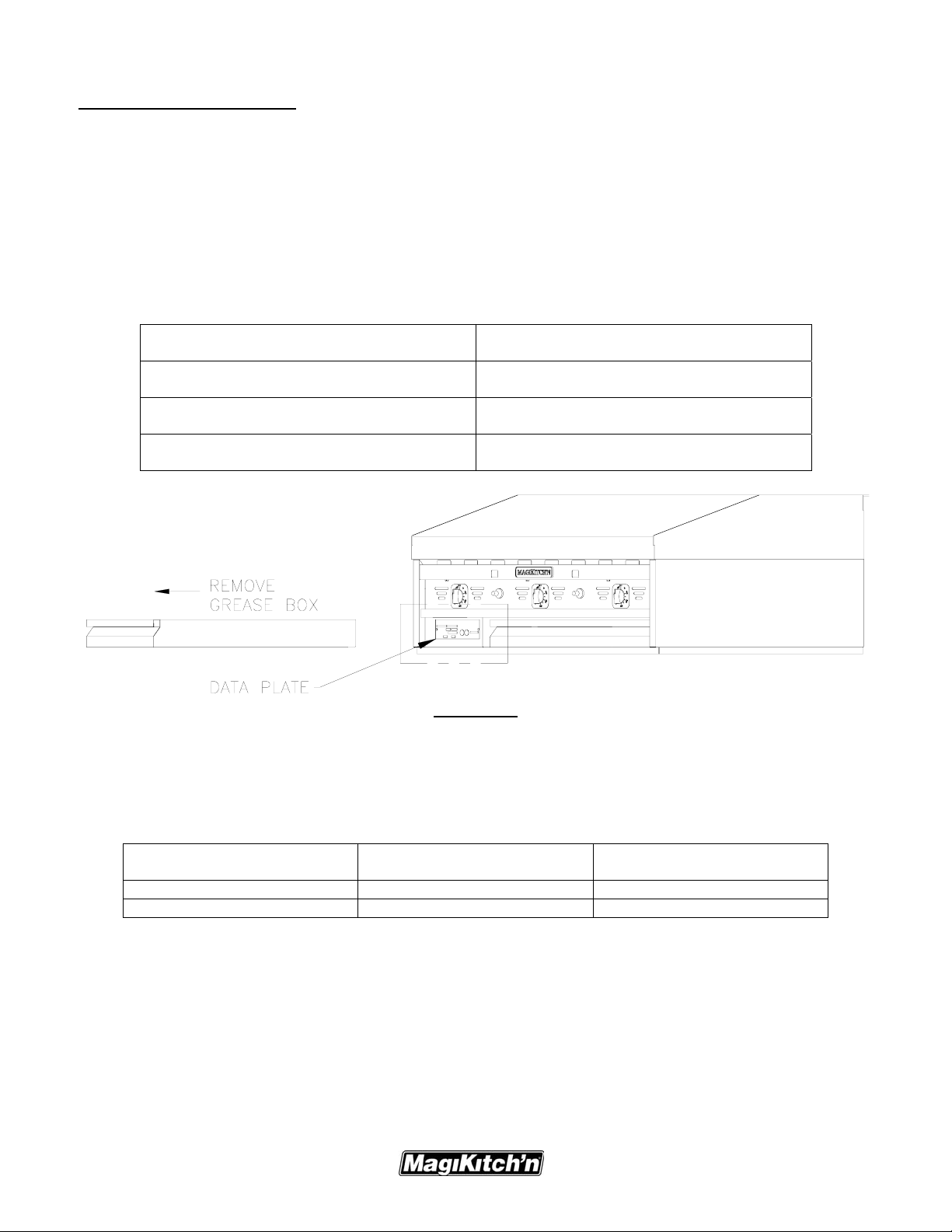
In the provided spaces below fill in the Model No., Serial No. and the date the appliance was received. Remove the grease
box and you will find the Information on the Data plate on the inside cabinet wall either on the left or right side, see figure
1 below. Keep this information in a safe place so it can be referred to in the future.
Model Number
Serial Number
Date of Installation
Purchased from
FIGURE #1
1.2. INSTALLATION CLEARANCES:
Your new MagiKitch’n Griddle needs clearance around it for proper operation. Adequate clearances allow for servicing
and proper burner operation. The clearances shown below are for installation in combustible and non-combustible
construction.
Location Combustible Construction
Inches (Centimeters)
Non-Combustible Construction
Inches (Centimeters)
Cabinet Back 8.0 (20.4) 8.0 (20.4)
Cabinet Sides 2.0 (5.0) 0.0 (0.0)
1.3. GAS CONNECTION:
Your gas appliance will give you peak performance when the gas supply line is of sufficient size to provide the correct gas
pressure. The gas line must be installed to meet the local building codes or National Fuel Gas Code ANSI Z223.1 Latest
Edition. In Canada, install the appliance in accordance with CAN/CGA-B149.1 or .2 and local codes. Gas line sizing
requirements can be determined by your local gas company by referring to the National Fuel Gas Code, Appendix C,
Table C-4 (for natural gas) and Table C-16 (for propane). The gas line needs to be large enough to supply the necessary
amount of fuel to all appliances without losing pressure to any appliance.
1
Page 5

MKG SERIES GAS GRIDDLE INSTALLATION & OPERATION
WARNING
NEVER supply the appliance with a gas that is not indicated on the data plate. Using the incorrect gas type will cause
improper operation. If you need to convert the appliance to another type of fuel, contact your dealer.
1.3.1. Fuel Types:
Each appliance is equipped to work with one type of fuel. The type of fuel with which the appliance is intended to
operate is stamped on the data plate, see figure 1.
CAUTION
NEVER use an adapter to make a smaller gas supply line fit the cooker connection. This may not allow proper gas flow
for the optimum burner operation, resulting in poor cooking performance.
1.3.2. Quick Disconnect Connection:
Gas appliances equipped with casters must be installed with connectors that comply with the Standard for Connectors
for Movable Gas Appliances, ANSI Z21.69.CSA 6.16 Latest Edition. This connection should include a quick
disconnect device that complies with the Standard for Quick Disconnect Devices for Use With Gas Fuel ANSI
Z221.41.CSA 6.9 Latest Edition. When installing a quick disconnect you must also install a means for limiting the
movement of the appliance. This device will prevent the gas line or the quick disconnects from being strained. The
restraining device should be attached to the appliance at the back panel.
1.3.3. Fuel Supply Line and Leak Pressure Testing:
The fuel supply system must be tested before the appliance is used. If the fuel line is going to be tested at a pressure
greater than ½ PSIG (3.45 kPA), make sure that the appliance is disconnected from fuel line. If the fuel line is to be
tested at a pressure equal to or less than ½ PSIG (3.45 kPA), the appliance can be connected, but the unit’s gas valve
must be shut. Test all gas line connections for leaks with a solution of soap and water when pressure is applied.
1.4. VENTILATION AND FIRE SAFETY SYSTEMS:
Your new gas appliance must have proper ventilation to function safely and properly. Exhaust gas temperatures can reach
as high as 1000°F (538 °C). Therefore, it is very important to install a fire safety system. Your ventilation system should
be designed to allow for easy cleaning. Frequent cleaning of the ventilation system and the appliance will reduce the
chances of fire. Table 1-2 provides a list of reference documents that provide guidance on ventilation and fire safety
systems. This table is not necessarily complete. Additional information can be obtained from CSA International, 8501 East
Pleasant Valley Rd., Cleveland, OH 44131.
Excessive ventilation causes drafts, which will interfere with the proper operation of the pilot and the burner. Leave at
least 18 inches of open space between the appliance’s flue vent opening and the intake of the exhaust hood.
CAUTION
Ensure that your ventilation system does not cause a down draft at the appliance’s flue opening. Down drafts will not
allow the appliance to exhaust properly and will cause overheating which may cause permanent damage. Damage
caused by down drafts will not be covered under equipment warranty. NEVER allow anything to obstruct the flow of
combustibles or ventilation exiting the appliance flue. DO NOT put anything on the top of the flue area.
CAUTION
NEVER connect the blower directly to the flue opening(s). The direct flow of air will cause poor temperature recovery,
poor ignition, and inefficient operation of the appliance and could extinguish the pilot(s).
2
Page 6

MKG SERIES GAS GRIDDLE INSTALLATION & OPERATION
1.5. INSTALLATION, SET UP:
The installation of this appliance MUST conform to local codes. In the absence of local codes, the installation must
conform to the National Fuel Gas Code, ANSI Z223.1; Natural Gas Installation Code, CAN/CGA-B149.1; or Propane
Installation Code, CAN/CGA-B149.2 as applicable.
A. Uncrate appliance and locate installation accessories shipped with the appliance.
1.5.1. For Counter Use With Legs:
CAUTION
To prevent equipment damage, DO NOT tilt your MagiKitch'n
griddle on only two legs, or on its sides.
A. (See picture at right) A set of 4” legs is shipped with the
appliance (unless appliance was specifically ordered
without legs). A threaded receptacle is located near each
corner of the underside of the base of the appliance, on
appliances 48" and wider there are threaded receptacles
in the front and rear center of the base. Each leg has a
similar mating thread. Raise appliance sufficiently to
allow legs to be screwed tightly into receptacles. The
appliance can be leveled by adjusting the feet at the
bottom of the leg assembly. This can be done by turning
the foot in or out to lower or raise each corner as
needed.
NOTICE
4" Legs should not to be used with the optional Equipment Stand.
CAUTION
The appliance must be level to perform properly. Failure to level unit may result in improper combustion and performance of
the appliance.
1.5.2. For Counter Use Without Legs:
A. (See picture at right) The appliance must be sealed to the
counter to comply with applicable sanitation standards. A
bead of silicone sealant, approximately ½ inch wide, is to
be applied to the bottom of the unit approximately ¼” in
from the front, back and side edges. We suggest Dow
Corning ®, GE ® or Permatex ® silicone ‘RTV’ adhesive
sealant or equivalent. (See NSF Basic Criteria C-2 for
details).
3
Page 7

MKG SERIES GAS GRIDDLE INSTALLATION & OPERATION
1.5.3. For Use on Optional Equipment Stand:
ATTENTION
Rear mounting brackets should be installed
to the Equipment Stand prior to placing griddle on the stand.
CAUTION
Only two of the four supplied casters are equipped with a locking
feature. Install the griddle so that the two locking casters are at the
front of the unit. The casters should be LOCKED before the unit is
placed into operation.
(See pictures this page). To mount the griddle to the stand,
locate joining kit supplied with stand. The joining kit should
include (2) rear mounting brackets, and (4) 1/2" mounting bolts.
To mount the griddle to the equipment perform the following
steps:
NOTICE
The larger units have 6 threaded receiving holes, but require
only the four 1/2" bolts on each corner to mount the griddle.
Step 1- Remove (4) existing 1/4-20 nuts and bolts from
the rear corners of the equipment stand.
Step 2- Align the 2 bolt holes on the rear corners of the
stand with the 2 bolt holes on the rear mounting brackets.
Orient the brackets as shown in the pictures on this page.
Step 3- Install the provided rear mounting brackets (2) to
the rear corners by using the existing 1/4-20 hardware that
were removed in step 1, tighten securely.
Step 4- Carefully place the griddle on the equipment
stand.
Step 5- Once the griddle is on the stand position the
griddle on the stand so that the front edge of the base is
flush with the front of the equipment stand. If the griddle
is the only appliance to be mounted on the stand, then
both sides of the griddle should be flush with the sides of
the equipment stand.
Step 6- When positioned properly, the threaded receiving
holes in the griddle base should be aligned with mating
clearance holes at the front of the equipment stand, and
with the clearance holes in the rear mounting brackets.
Install the provided 1/2" bolts and tighten securely.
NOTICE
This appliance may only be installed with casters provided by
the manufacturer. When installed with casters, a gas
connection complying with ANSI Z21.69/CGA-6.16 and a
quick disconnect device complying with ANSI Z21.41/CAN 1-
6.9. It must also be installed with a restraining device to
guard against putting any strain on the gas connections when
the unit is moved.
4
Page 8

MKG SERIES GAS GRIDDLE INSTALLATION & OPERATION
1.6. FINAL GAS CONNECTION:
A properly installed gas supply system will deliver adequate pressure (7 to 8 inches w.c. for natural gas, 11 to 12 inches
w.c. for propane) to all appliances connected to the line, operating at full demand.
1.6.1. Regulator Assembly:
An adequate gas supply is important for the appliance to operate properly. Undersized lines or low-pressures will restrict the
volume of gas required for satisfactory performance. A steady supply pressure between 7” and 8” w.c. for natural gas or 11” to
12” for propane gas is required. With all gas appliances operating simultaneously, the manifold pressure on all gas appliances
should not show any appreciable drop. Fluctuations of more than 25% on natural and 10% on propane gas will create pilot
problems and affect burner operating characteristics. Contact your gas company for correct supply line sizes. After connection,
a certified gas service agent should check all newly installed equipment for correct gas pressure. The unit should be connected
ONLY to the type of gas for which it is equipped. Check the type of gas on the serial plate.
FIGURE #2
A. Attach regulator supplied with the appliance to the gas inlet supply pipe located at the rear of the unit.
Appliances equipped with Matchless Ignition controls are also supplied with a ¾” manual shut off valve. Be
sure regulator is connected so that gas flow is in the direction of the arrow on the bottom of the regulator. See
figure #2 for the correct installation of the regulator piping components. Using a regulator other than the one
supplied with the unit will void the warranty.
B. The manifold pressure must be maintained at the pressure marked on the Data plate. For appliances equipped
with Solid State or Electric Thermostat controls the pressure reading is taken at the pressure tap supplied on
the ¾” manual shut off valve, see figure #2. For all other griddles, a pressure tap is located behind the door
on the 1.0" square manifold, see figure #3.
C. Use pipe joint compound that is suitable for use with LP gas on all threaded connections.
D. Turn off all thermostats.
E. Turn on gas supply and check all connections for leaks using ONLY a leak checking fluid or soapy water.
NEVER use an open flame to check for gas leaks.
F. Provision must be made for adequate air supply for both the appliance and room occupants.
G. Keep area in front of unit free from obstruction that could block flow of combustion and/or ventilation air.
H. Be certain that adequate clearance is maintained so that air openings in front of the unit are not blocked and
any subsequent service can be performed. Ensure that rear and side clearances stated on the serial plate and in
the clearance section of this manual are strictly followed.
5
Page 9

MKG SERIES GAS GRIDDLE INSTALLATION & OPERATION
1.6.2. Gas Settings:
Orifices are sized to provide proper gas flow to the rated
BTU/hr for each model. Regulator pressure must be measured
and adjusted before the unit goes into service, following
installation and when operational performance is in question.
Gas Type BTU/hr(kW)
Per Burner
Natural 15,000(4.4) 4.0"(10.1cm) 4.5"(11.4cm)
Propane 15,000(4.4) 10.0"(25.4cm) 10.0"(25.4cm)
2. OPERATION SECTION:
Ensure that a proper installation has been performed on the appliance and that all warnings, cautions, and notices contained in
this manual have been read, understood and adhered to before proceeding.
2.1. LIGHTING INSTRUCTIONS:
2.1.1. Snap Action Thermostat Appliances:
A. Turn all thermostat knobs to the “OFF” position.
B. Open front door of the griddle, turn the manual gas
shut off valve to the “ON” position.
C. Press and hold the leftmost RED pilot button, see
detail Method A at right, and light the leftmost pilot
with a flame source, through the left pilot hole, or
depress the Piezo ignition control (If Provided). With
pilot burning, keep the RED pilot knob depressed for
45 seconds or until pilot remains lit automatically.
D. Repeat steps A, B, and C for all remaining pilots.
Manifold
Pressure
WC"
(Matchless)
Manifold
Pressure
WC"
(All Others)
FIGURE #3
E. Operate thermostats by turning knobs clockwise to the desired temperature and insure that burners light
properly by looking through the pilot holes provided in the front panel.
NOTICE:
If appliance contains more than one pilot, the leftmost pilot MUST be lit first or the other pilot WILL NOT LIGHT.
2.1.2. Solid State and Electric Thermostat Appliances:
A. Turn all thermostat knobs to the “OFF” position, or the
lowest possible temperature setting.
B. Turn the Manual gas shut off valve to the "ON" position,
this valve is located at the rear of the unit, see Figure #2.
C. Turn the RED "I/O" switch to the “I”(ON) position for
all desired Thermostats to be operated, See detail
Method B at right. When the Pilot ready (Amber) light
illuminates, the pilot(s) are ready to operate the main burners.
D. Repeat for all thermostat controls to be operated.
E. Operate thermostats by turning knobs clockwise to the desired temperature and insure that burners light
properly by looking through the pilot holes provided in the front panel.
The RED "I/O" switch will illuminate when the thermostat calls for heat.
CAUTION
If Pilot Ready light(s) does not illuminate, Turn all Thermostat "I/O" switches for that pilot to “O”(OFF), wait five
minutes before attempting to re-light.
If Pilot(s) extinguish or gas supply is interrupted, turn thermostat knobs and the gas shut off valve to the "OFF"
position and wait 5 minutes before attempting to re-light.
6
Page 10

MKG SERIES GAS GRIDDLE INSTALLATION & OPERATION
2.2. INITIAL STARTUP:
NOTICE:
New griddles should be carefully tempered and cared for in order to avoid possible damage. To break in a new griddle,
do the following:
Wipe the griddle surface clean. A mild soapy water solution may be used to clean the surface, if this solution is used be sure to
rinse thoroughly with fresh water to eliminate any soap residue. Also it is important to wipe the griddle surface and
surrounding areas to dry up any standing water. Never allow water on a hot griddle surface.
Seasoning is not required on a Chrome Plated Cooking surface, but the following procedure may be performed to improve the
non-stick qualities of the chrome plated cooking surface.
2.2.1. Griddle Surface Seasoning:
A. To season the griddle, light all the griddle burners and set the thermostats to 200°F. As the unit heats up to 200°F,
apply a light film of cooking oil or beef suet over the entire cooking surface, wiping off any excess build up. This
step may be repeated as necessary to apply an even coating on the griddle surface. Seasoning will help create and
maintain a non-stick surface on your griddle.
B. Allow the seasoned surface to idle for one hour at 200°F, Then set the thermostats to your desired cooking
temperature, once your griddle surface has reached temperature apply another coating of seasoning oil, wiping off
any excess that may cause build up.
2.2.2. Surface Temperature Check:
A. If available, place grill surface thermometer over each thermostat sensing probe 12" from the front edge of the
griddle surface. The first sensing probe is located 6" from the left side of the griddle, additional sensing probes
are every 12" to the right thereafter.
B. Heat the griddle up to the desired cooking temperature; check the surface temperature reading on the grill
thermometer. If necessary, adjust the thermostats that control any area of the surface that are not within +/- 15°F
of the thermostat setting. The procedure for adjusting the thermostats is in Section 3.
2.3. SHUTDOWN PROCEDURE:
2.3.1. Snap Action Thermostat Appliances:
A. Turn thermostat knobs to the “OFF” position.
B. Turn gas shut off valve to “OFF” position.
C. Allow griddle surface to cool normally.
2.3.2. Solid State and Electric Thermostat Appliances:
A. Turn thermostat knobs to the “OFF” position, or the lowest possible temperature setting.
B. Turn “I/O” Switch to “O” position. Close manual gas valve shut off.
C. Allow griddle surface to cool normally.
7
Page 11

MKG SERIES GAS GRIDDLE INSTALLATION & OPERATION
3. THERMOSTAT CALIBRATION SECTION:
Each control typically operates a pair of burners with a Snap action, Electric or Solid State. The controls were set at the
factory. However, if the griddle’s surface temperature varies greatly from the setting on the thermostat knob, adjust the
thermostat using the following procedure:
3.1. CALIBRATION PROCEDURES:
3.1.1. Snap Action and Electric Thermostats:
A. Light pilots per lighting
instructions.
B. Turn all the control knobs to the
desired temperature setting.
C. Wait 30 minutes (or 1 hour if
griddle was cold) for surface to
stabilize.
D. Place a reliable Griddle surface
thermometer,
or test instrument thermocouple, (able to register 300°F), in the location above the thermostat
being calibrated as described in section 2.3.2. Check the temperature every 5 minutes until the temperature
stabilizes and does not change by more than 30°F over a 15 minute time period.
NOTICE:
The adjustment screw in the thermostat is sealed at the factory to protect the calibration, it may be
necessary to remove this seal to be able to adjust the thermostat.
E. If the average temperature over any burner set is not within +/-15°F of the knob setting (300°F), adjust the
corresponding thermostat. This is done by removing the knob, holding the thermostat knob stem, see picture
this section, (do not allow the stem to turn or the temperature setting will not be accurate), then turn the
adjustment screw located within the center of the stem in small increments. Turn this screw counter
clockwise to increase the temperature, and clockwise to decrease the temperature.
F. Check the temperature after 15 minutes and repeat adjustment as needed until the correct temperature is
indication on the measuring instrument.
3.1.2. Solid State Thermostat:
A. Light pilots per lighting instructions.
B. Turn all the control knobs to the desired
temperature setting.
C. Wait 30 minutes (or 1 hour if griddle was
350
4
1
8
0
0
0
0
2
6
0
0
1
0
0
3
0
2
4
1
0
0
5
2
2
1
0
0
0
1
0
2
8
0
1
5
0
2
4
0
5
0
2
4
0
5
2
6
0
0
0
0
8
2
0
5
°
C
5
°F
350
4
1
8
0
0
0
0
2
6
0
0
1
0
0
3
0
2
4
1
0
0
5
2
2
1
0
0
0
1
0
2
8
0
1
5
0
2
4
0
5
0
2
4
0
5
2
6
0
0
0
0
8
2
0
5
°
C
5
°F
cold) for surface to stabilize.
D. Place a reliable Grill surface thermometer,
or test instrument thermocouple, (able to register 300°F), In the
location above the thermostat being calibrated described in the Surface Temperature Check section above.
Check the temperature every 5 minutes until the temperature stabilizes and does not change by more than
30°F over a 15 minute time period. You will need to remember the average temperature for the next step.
E. Carefully remove the cap on the thermostat knob with the white indicator line see picture this section. While
holding the knob, loosen the 5/16" nut on the thermostat shaft, (DO NOT REMOVE), once the nut is loose
the knob can be rotated so that the cap line marker is aligned with the actual temperature that the Grill
surface thermometer is indicating.
F. Re-tighten the 5/16" nut while holding the knob in position, (do not allow the stem to turn or the temperature
setting will not be accurate). Replace cap.
8
Page 12

MKG SERIES GAS GRIDDLE INSTALLATION & OPERATION
4. BASIC OPERATION:
4.1. OPERATIONAL HELPFUL HINTS:
A. Each thermostat controls 12" of griddle surface, whenever possible, use the leftmost or rightmost thermostats for the
lowest cooking temperatures. The adjacent thermostats set at higher temperatures will effect centrally located
thermostats.
B. For quicker thermostat response during heavy loading of the griddle, load product directly over the thermostat sensing
probe. For slow periods load product to one side of the sensing probe to limit possible overheating of unused griddle
surface.
C. Whenever possible, rotate the location of where product is cooked, this will keep the entire 12" of the controlled area
at a more even temperature.
D. If any product sticking occurs, apply a thin coat of cooking oil to the surface before loading product.
E. When using spatulas or scrapers, it is Highly Recommended that the corners of the tools never strike the griddle
surface with any force. This could cause damage to the surface that could collect food particles, and make it difficult
to clean.
4.2. SUGGESTED COOKING TIMES & TEMPERATURES:
NOTICE:
The times and temperatures in this chart are suggestions only. Your experience with your own menu
items will be your best guide to achieving the best food product.
Product Temperature °F Time
Breakfast Items
Pancakes 375° 2 Minutes
French Toast 400 4-5 Minutes
*Breakfast Potatoes 375-400° 15-20 Minutes
Eggs
Scrambled 300° 3-4 Minutes
Sunny Side Up 225-300° 3-4 Minutes
Over Easy 250-300° 2-3 Minutes
Over Hard 225-300° 3-4 Minutes
Breakfast Meats
Sausage, Link and Patty 350° 3 Minutes
Bacon 350° 2-3 Minutes
Canadian Bacon 350° 2-3 Minutes
Ham Steaks 375° 3-4 Minutes
Broiled Ham 375° 2 Minutes
Ham, Precooked 375° 2 Minutes
Fish
Salmon 350° 6-8 Minutes
Hamburgers
2 Patties per LB. 350° 6-8 Minutes
4 Patties per LB. 350° 4-6 Minutes
6 Patties per LB. 350° 3-4 Minutes
Steaks, etc.
1/2"-3/4"Thick,Medium 375° 5-7 Minutes
3/4"-1" Thick, Medium 375° 8-10 Minutes
Beef Tenderloin 400° 3-4 Minutes
Sandwiches, etc.
Grilled Cheese 375° 3-4 Minutes
Hot Dogs 325° 2-3 Minutes
*Based on cubed potatoes brought to a boil then cooled prior to finishing on griddle. To reduce burning and sticking of
the potatoes, coat the griddle surface with vegetable oil and turn potatoes frequently.
9
Page 13

MKG SERIES GAS GRIDDLE INSTALLATION & OPERATION
5. CLEANING & MAINTENANCE SECTION:
5.1. DAILY CLEANING:
A. Clean the griddle surface often to prevent sticking and poor quality of food product. Scrape the griddle plate regularly
with a scraper intended for your type of griddle surfaces to remove all surface grease and food debris.
NOTICE:
Do not use Grill Bricks, Grill Screens, or any other type of abrasive material on your
MagiKitch'n Chrome Griddle Surface. USING ABRASIVE MATERIALS WILL VOID YOUR WARRANTY.
B. Clean and wipe out grease chutes.
C. Wipe down the exterior, the sides and front of the griddle are stainless steel, any stainless steel cleaner can be used to
clean these surfaces.
D. Remove and empty grease box(es) of any and all debris, also wipe down the inside of the grease box compartment for
food particles that may have come free from the grease box.
NOTICE:
The grease box is designed to contain grease run off from the griddle surface. The grease box should NEVER be
allowed to overfill, and should be emptied daily and the grease disposed of properly.
5.2. GRIDDLE SURFACE CLEANING, END OF SHIFT:
5.2.1. Plain Steel Cooking Surface:
A. Scrape griddle surface completely with a scraper to remove grease and loose food debris.
B. Use a grill brick or grill screen to clean any heavy build up of carbon from the griddle surface. Never use
steel wool pads, small fibers may be left behind on the cooking surface.
C. When griddle surface is cool, Polish surface with Magi Kleans'r, or similar type non-abrasive, non-caustic
cleaners that are approved for stainless steel.
D. It may be necessary to season the grill again after this cleaning.
5.2.2. Chrome Plated Cooking Surface:
A. Scrape griddle surface completely with supplied scraper to remove grease and loose food debris.
NOTICE:
Do not use Grill Bricks, Grill Screens, or any other type of abrasive material on your
MagiKitch'n Chrome Griddle Surface. USING ABRASIVE MATERIALS WILL VOID YOUR WARRANTY.
B. When griddle surface is cool, Scrub the Chrome surface with the supplied palmetto cleaning brush and cool
water.
C. Shine the Chrome griddle cooking surface with Magi Kleans'r, water and a soft cloth.
D. Rinse with clean water and wipe away any residue with a dry cloth.
5.3. MONTHLY MAINTENANCE:
NOTICE:
Regular maintenance of your MagiKitch'n griddle is Recommended to keep the appliance operating properly.
5.3.1. Monthly Checks:
A. Use a grill surface thermometer to make sure thermostats are operating properly.
B. Through the pilot holes in the front panel, visually check that the pilot(s) flame(s) are strong and light the
main burners properly.
C. Through the pilot holes in the front panel, visually check the appearance of the main burners, all burners
should have a nice blue flame.
D. Make sure that all gas connections have not been tampered with or damaged, check for leaks with a soapy
water solution. Never use an open flame to check for leaks.
E. Check to see that the flue exhaust area has no food debris, or blocked in any way. Never allow the flue to
become excessively dirty. The flue being free of obstruction is imperative to proper burner operation.
10
Page 14

MKG SERIES GAS GRIDDLE INSTALLATION & OPERATION
F. Check to see that the ventilation hood and make up air systems are working properly. Any make up air
system should not be directed as to impede the flow of combustion air to the griddle, or flue exhaust from the
griddle.
G. Inspect griddle surface for proper cleanliness.
5.4. TROUBLESHOOTING CHART:
The following chart may help to eliminate any basic operational problems that you may be experiencing with your
appliance. Locate the problem on the left side of the chart, and cross-reference the problem with the possible cause. Once
the problem has been identified take the appropriate action to rectify the problem.
NOTICE:
All parts and service for your MagiKitch'n griddle should be ordered and installed by a MagiKitch'n Authorized
Service and Parts (ASAP) dealer. Failure to do so might result in the warranty being voided.
POSSIBLE CAUSE
PROBLEM
Excessive
Smoke
From Fat
Product
Sticking
Heat
Set
Too
High
XX
XXX
Moisture
in Food
Turning
Into
Steam
Griddle
Surface
Dirty or
Un-
seasoned
Cooking
Times
Not Long
Enough
Product
Shelf Life
Expired
Product
Stored
In-
correctly
Excessive
Oil or
Fat used
on
Griddle
Surface
Heat Set
Too Low
Product
Edges
Burning
Product
Centers
Underdone
Greasy or
Undesirable
Flavor
Grease
Build up on
Griddle
Surface
5.5. ACCESSORIES:
5.5.1. Standard:
Standard accessories that are shipped with your MKG griddle, all griddles are shipped with a set of 4" legs, black iron
piping(for gas connections), 3/4" 1/2 PSIG gas regulator, and a 3/4" shut off valve on Matchless ignition units.
Each MKG Chrome Surfaced Griddle is equipped with a Chrome Kit which includes a Cleaning Brush, Cleaning
Powder, Spatula, Scraper, and scrape blade replacements. See below table for re-order Part Nos.
XXX
XX
XXX
XX X
CHROME GRIDDLE ACCESSORIES
Magi Kleans'r Part No. 9825-1525101
Palmetto Brush Part No. 9825-1524901
Spatula(Chrome Surface) Part No. 9825-1525001
Scraper, w/ blade and cover Part No. 9825-1528001
Replacement blades Part No. 9825-1528002
11
Page 15

MKG SERIES GAS GRIDDLE INSTALLATION & OPERATION
Using MagiKitch'n chrome griddle accessories are important to
maintaining the life of the griddle's chrome surface.
5.5.2. Optional:
To order accessories for your griddle, call your local MagiKitch’n dealer for prices and availability.
Accessories by Model MKG24 MKG36 MKG48 MKG60 MKG72
Service Shelf 8" 5125-1511601-C 5125-1511602-C 5125-1511603-C 5125-1511610-C 5125-1511611-C
Service Shelf 10" 5125-1511604-C 5125-1511605-C 5125-1511606-C 5125-1511612-C 5125-1511613-C
Service Shelf 12" 5125-1511607-C 5125-1511608-C 5125-1511609-C 5125-1511614-C 5125-1511615-C
Service Shelf 8" with Towel Bar 5225-1511701-C 5225-1511702-C 5225-1511703-C 5225-1511710-C 5225-1511711-C
*Service Shelf 10" with Towel Bar 5225-1511704-C 5225-1511705-C 5225-1511706-C 5225-1511712-C 5225-1511713-C
*Service Shelf 12" with Towel Bar 5225-1511707-C 5225-1511708-C 5225-1511709-C 5225-1511714-C 5225-1511715-C
Towel Bar Only 5225-1511801-C 5225-1511802-C 5225-1511803-C 5225-1511804-C 5225-1511805-C
**Griddle Stand with Legs 5225-1512001-C 5225-1512005-C 5225-1512007-C 5225-1512009-C 5225-1512011-C
**Griddle Stand with Casters 5225-1512002-C 5225-1512006-C 5225-1512008-C 5225-1512010-C 5225-1512012-C
*10" & 12" service shelves are also available with cutting boards and/or pan cutouts. Consult factory for availability.
**Also include part number 7225-1512101 (mounting kit) with any griddle stand order.
12
Page 16

MAILING ADDRESS - P.O. BOX 501, CONCORD, NH 03302-0501
SHIPPING ADDRESS - 10 FERRY ST. CONCORD, NH 03301
PHONE- 800-258-3708 • 603-225-6684 • FAX: 603-225-8497
www.magikitchn.com
 Loading...