

Page 1
IMPORTANT FOR FUTURE REFERENCE
Please complete this information and retain this manual
for the life of the equipment:
Model #: __________________________
Serial #: __________________________
Date Purchased: ___________________
Exploded Parts Manual
MKE: MagiKitch’n Electric Griddle
March 2011
L22-333, rev. 0 (3/11)
Page 2

TABLE OF CONTENTS MKE PARTS MANUAL
WARNING
DO NOT store or use gasoline or other flammable
vapors and liquids in the vicinity of this or any
other appliance.
WARNING
Improper installation, alteration, service or
maintenance can cause property damage, injury
or death. Read the installation, operating and
maintenance instructions thoroughly before
installing or servicing this appliance.
WARNING
Installation, maintenance and repairs should be
performed by a MagiKitch’n Authorized Service
and Parts (ASAP) company technician or other
qualified personnel. Installation, maintenance or
repairs by an unauthorized and unqualified
personnel will void the warranty.
WARNING
Installation and all connections must be made
according to national and local regulations and
codes in force.
WARNING
A country approved all pole circuit breaker with a
minimum open contact gap of 3mm must be used
for proper installation. (CE countries)
WARNING
During the warranty period if a customer elects to
use a non-original part or modifies an original part
purchased from MagiKitch’n and/or its Authorized
Service and Parts (ASAP) companies, this
warranty will be void. In addition, MagiKitch’n
and its affiliates will not be liable for any claims,
damages or expenses incurred by the customer
which arises directly or indirectly, in whole or in
part, due to the installation of any modified part
and/or received from an unauthorized service
center.
WARNING
This appliance, when installed, must be
electrically grounded in accordance with local
codes, or in the absence of local codes, with the
National Electrical Code, ANSI/NFPA 70, or the
Canadian Electrical Code, CSA C22.2, as
applicable.
WARNING
Adequate means must be provided to LIMIT the
movement or this appliance without depending on
the electrical cord connection. Single appliances
equipped with legs must be stabilized by
installing anchor straps. All appliances equipped
with casters must be stabilized by installing
restraining chains.
WARNING
DO NOT alter or remove structural material on the
appliance to accommodate placement under a
ventilation hood.
WARNING
This appliance is intended for professional use
only and should be operated by fully trained and
qualified personnel.
WARNING
If the supplied power cord is damaged, it must be
replaced by a MagiKitch’n Authorized Service and
Parts (ASAP) company technician, or a similarly
qualified person in order to avoid a hazard.
WARNING
The power supply must be disconnected before
servicing, maintaining or cleaning this appliance.
WARNING
The appliance is NOT jet stream approved. DO
NOT clean the appliance with a water jet.
WARNING
DO NOT attempt to move this appliance or
transfer hot liquids from one container to another
when the unit is at operating temperature or filled
with hot liquids. Serious personal injury could
result if skin comes in contact with the hot
surfaces or liquids.
WARNING
DO NOT sit or stand on this appliance. The appliance’s
front panel, cook plate, splash back, side, workshelf not
a step. Serious injury could result from slipping, falling
or contact with hot surfaces or liquids.
WARNING
NEVER use the appliance as a step for cleaning or
accessing the ventilation hood. Serious injury could
result from slips, trips or from contacting hot surfaces
or liquids.
WARNING
DO NOT use the appliance unless it is properly secured
to a table, stand or freezer / refrigerated base suited to
handle the weight of the entire appliance.
WARNING
DO NOT operate appliance unless all panels and
access covers are attached correctly.
WARNING
It is recommended that this appliance be
inspected by a qualified service technician for
proper performance and operation on a yearly
basis.
L22-333, rev. 0 (3/11)
Page 3

MKE EXPLODED......................................................................................3
MKE Exploded Parts List ....................................................................................................................3
MKE Exploded Drawing ......................................................................................................................4
SECTION B: COMPONENT PANEL ........................................................5
Component Panel Drawing B Parts List............................................................................................5
Component Panel Drawing B .............................................................................................................6
SECTION C: COMPONENT HEAT SHIELD ............................................7
Component Heat Shield Drawing C Parts List..................................................................................7
Component Heat Shield Drawing C ...................................................................................................8
SECTION D: SWITCH PANEL .................................................................9
Switch Panel Drawing D Parts List ....................................................................................................9
Switch / Control Panel Drawing D....................................................................................................10
SECTION E: CABINET...........................................................................11
Cabinet Parts list E............................................................................................................................11
Cabinet Drawing E.............................................................................................................................12
SECTION F: ELEMENTS, UPPER HEAT SHIELD, AND CABINET
BACKS....................................................................................................13
Elements, Upper Heat Shield, and Cabinet Backs Drawing F Parts List .....................................13
Elements, Upper Heat Shield, and Cabinet Backs Drawing F.......................................................14
L22-333, rev. 0 (3/11)
Page 4
MKE Exploded
MKE Exploded Parts List
QUANTITY
P/N DESC.
MKE24
MKE36
MKE48
MKE60
ITEM #
5125-1557801-C TOP WELDMENT MKE24 1
5125-1557802-C TOP WELDMENT MKE36 1
1
5125-1557803-C TOP WELDMENT MKE48 1
1
5125-1557804-C TOP WELDMENT MKE60 1
5125-1557805-C TOP WELDMENT MKE72 1
5125-1557806-C TOP WELDMENT MKE24 CHROME 1
5125-1557807-C TOP WELDMENT MKE36 CHROME 1
1
5125-1557808-C TOP WELDMENT MKE48 CHROME 1
2
5125-1557809-C TOP WELDMENT MKE60 CHROME 1
5125-1557810-C TOP WELDMENT MKE72 CHROME 1
5125-1557902-C TOP WELDMENT 36 CHROME LH TRH 1
1
5125-1557903-C TOP WELDMENT48 CHROME LH TRH 1
3
5125-1557904-C TOP WELDMENT60 CHROME LH TRH 1
B
1
B
2
C
SEE
SECTION B
SEE SECTION C: COMPONENT HEAT SHIELD
D
E
SEE SECTION F: ELEMENTS, UPPER HS AND CAB BACKS
F
CONTACTOR ASS'Y 2 ZONE SOLID STATE 1 2 1 2 1
CONTACTOR ASS'Y 3 ZONE SOLID STATE 1 1 2 1 1
CONTACTOR ASS'Y 2 ZONE ELEC. TSTAT 1 2 1
CONTACTOR ASS'Y 3 ZONE ELEC. TSTAT 1 1 2
ONE PER UNIT
SEE SECTION D: FRONT PANELS
SEE SECTION E: CABINET
ONE PER UNIT
ONE PER UNIT
ONE PER UNIT
MKE72
FG-MKE36
FG-MKE48
FG-MKE60
L22-333, rev. 0 (3/11)
Page 5
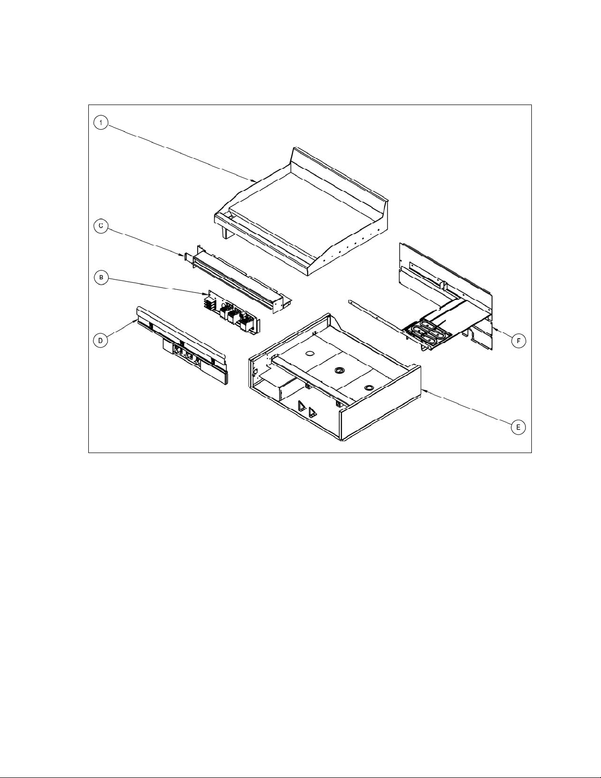
MKE Exploded Drawing
L22-333, rev. 0 (3/11)
Page 6

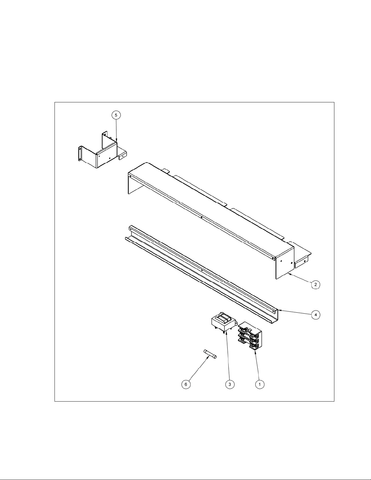
SECTION B: Component Panel
Component Panel Drawing B Parts List
P/N DESCRIPTION
ITEM #
5425-1554801-C CONTACTOR BRACKET 3ZONE 1 1
1
5425-1554803-C CONTACTOR BRACKET 2ZONE 1 1
2 P5047301 BLOCK, TERMINAL 3 POST 1111
3 60145301 LUG, GROUND ALUMINUM 1111
4 60157202 CONTACTOR, DP 3P 50A 600V 24V 3232
5 P6071228 GROMMET, 1.703ID, 2.000 GROOVE 2121
6 P5046686 RELAY, 24VAC DPDT W/ TABS 3 2
7 PP11222 SCREW, 10-24X .500 RH PH ZN 4444
8 PP10693 SCREW, 10-24X .375 TH PH ZN 6464
9 P0075400 SCREW, 10-24X .500 SELF TAP 1111
10 P0092300 NUT, HEX KEP 10-24 ZN 1111
11 PP10686 SCREW, 6-32X .25 RH PH ZN 6 4
QUANTITY
3 ZONE SST
2 ZONE SST
3 ZONE E TSTAT
2 ZONE E TSTAT
L22-333, rev. 0 (3/11)
Page 7

Component Panel Drawing B
L22-333, rev. 0 (3/11)
Page 8

SECTION C: Component Heat Shield
Component Heat Shield Drawing C Parts List
QUANTITY
# P/N DESCRIPTION
MKE24
MKE36
MKE48
MKE60
MKE72
FG-MKE36
1 P5045792 FUSEBLOCK, 3 POST 300V 60A 22444244
5425-1554202-C HEAT SHIELD COMPONENT 24 1
5425-1554204-C HEAT SHIELD COMPONENT 36 1 1
2
5425-1554206-C HEAT SHIELD COMPONENT 48 1 1
5425-1554208-C HEAT SHIELD COMPONENT 60 1 1
5425-1554210-C HEAT SHIELD COMPONENT 72 1
3 PP10210 TRANSFORMER, 40VA 120-208-240 TO 24 23456345
5425-1555801-C HEAT SHIELD, SWITCH PANEL BRACKET 24 1
5425-1555803-C HEAT SHIELD, SWITCH PANEL BRACKET 36 1 1
4
5425-1555805-C HEAT SHIELD, SWITCH PANEL BRACKET 48 1 1
5425-1555807-C HEAT SHIELD, SWITCH PANEL BRACKET 60 1 1
5425-1555809-C HEAT SHIELD, SWITCH PANEL BRACKET 72 1
5425-1556201-C HEAT SHIELD, END LEFT 11111111
5
5425-1556203-C HEAT SHIELD, END RIGHT 1
6 P5045701 FUSE, 40A SLOW BLOW 6 6 12 12 12 6 12 12
FG-MKE48
FG-MKE60
L22-333, rev. 0 (3/11)
Page 9
Component Heat Shield Drawing C
L22-333, rev. 0 (3/11)
Page 10
SECTION D: Switch Panel
Switch Panel Drawing D Parts List
QUANTITY
# PART NUMBER DESCRIPTION
MKE24
MKE36
MKE48
MKE60
MKE72
FG-MKE36
FG-MKE48
FG-MKE60
MKE24 E-TSTAT
1 60129403 KNOB,COLLET .25" W/PNTR&CAP 23456345
5425-1554202-C SWITCH PANEL MKE24 1 1
5425-1554204-C SWITCH PANEL MKE36 1 1
5425-1554206-C SWITCH PANEL MKE48 1 1
5425-1554208-C SWITCH PANEL MKE60 1 1
2
5425-1554210-C SWITCH PANEL MKE72 1 1
5425-1554214-C SWITCH PANEL FG-MKE36 1
5425-1554216-C SWITCH PANEL FG-MKE48 1
5425-1554218-C SWITCH PANEL FG-MKE60 1
3 60172301 SWITCH, 24VDC DPDT 2345634523456
5425-1548401-C CONTROL MOUNTING BRACKET 24 1 1
5425-1548402-C CONTROL MOUNTING BRACKET 36 1 1 1
4
5425-1548403-C CONTROL MOUNTING BRACKET 48 1 1 1
5425-1548404-C CONTROL MOUNTING BRACKET 60 1 1 1
5425-1548405-C CONTROL MOUNTING BRACKET 72 1 1
5425-1519102-C LOWER FRONT PANEL RIGHT 1 1
5425-1519104-C LOWER FRONT PANEL RIGHT 1 1 1
5
5425-1519106-C LOWER FRONT PANEL RIGHT 1 1 1
5425-1519108-C LOWER FRONT PANEL RIGHT 1 1 1
5425-1519101-C LOWER FRONT PANEL LEFT 1 1
5425-1519103-C LOWER FRONT PANEL LEFT 1 1 1
6
5425-1519105-C LOWER FRONT PANEL LEFT 1 1 1
5425-1519107-C LOWER FRONT PANEL LEFT 1 1 1
5425-1519109-C LOWER FRONT PANEL 72 2 2
7
8 A6087302 LABEL, TEMP 150-550 23456345
60142502 CONTROLLER SOLID STATE 24VAC 23456345
60142801 CONTROLLER ELECTRIC 24VAC* 23456
MKE36 E-TSTAT
MKE48 E-TSTAT
MKE60 E-TSTAT
MKE72 E-TSTAT
L22-333, rev. 0 (3/11)
Page 11

Switch / Control Panel Drawing D
L22-333, rev. 0 (3/11)
Page 12
SECTION E: Cabinet
Cabinet Parts list E
QUANTITY
P/N DESC.
MKE24
MKE36
MKE48
MKE60
ITEM #
5225-1532601-C CABINET SIDE, MKG RH 11111
1
5225-1539301-C CABINET SIDE RH MKG 5 GUYS 1 1 1
5225-1532602-C CABINET SIDE, MKG LH 11111
2
5225-1539302-C CABINET SIDE LH MKG 5 GUYS 1 1 1
5425-1519101-C CABINET BOTTOM OUTER 24 1
5425-1519102-C CABINET BOTTOM OUTER 36 1 1
3
5425-1519103-C CABINET BOTTOM OUTER 48 1 1
5425-1519104-C CABINET BOTTOM OUTER 60 1 1
5425-1519105-C CABINET BOTTOM OUTER 72 1
5125-1519201-C CABINET FRONT AND REAR 24 1
5125-1519202-C CABINET FRONT AND REAR 36 1 1
4
5125-1519203-C CABINET FRONT AND REAR 48 1 1
5125-1519204-C CABINET FRONT AND REAR 60 1 1
5125-1519205-C CABINET FRONT AND REAR 72 1
5425-1519006-C CABINET SUPORT MID 24 1
5425-1519007-C CABINET SUPORT MID 36 1 1
5
5425-1519008-C CABINET SUPORT MID 48 1 1
5425-1519009-C CABINET SUPORT MID 60 1 1
5425-1519010-C CABINET SUPORT MID 72 1
5425-1530501-C GREASE BOX, ENCLOSURE LH 11111
6
5425-1530502-C GREASE BOX, ENCLOSURE RH 1
5425-1530503-C GREASE BOX, ENCLOSURE SD TRH 1 1 1
7 P6071228 GROMMET, 1.703ID, 2.000 GROOVE 12345234
8 P6071448 PLUG, 2.000 SHEET METAL 11111
5425-1539902-C GREASE BOX, FLOOR LH 11111111
9
5425-1539904-C GREASE BOX, FLOOR RH 1
10 5425-1530601-C LOWER FRONT PANEL CLIP RH 1111 111
11
5425-1555901-C SUPPORT, CONTROLLER PANEL 12222222
12
5425-1553401-C CABINET, INNER UPRIGHT SUPPORT 12345234
5425-1554001-C CABINET INNER FRONT 24 1
5425-1554003-C CABINET INNER FRONT 36 1 1
13
5425-1554005-C CABINET INNER FRONT 48 1 1
5425-1554007-C CABINET INNER FRONT 60 1 1
5425-1554009-C CABINET INNER FRONT 72 1
5425-1530901-C CABINET, REAR SUPPORT 24 1
5425-1530902-C CABINET, REAR SUPPORT 36 1 1
14
5425-1530903-C CABINET, REAR SUPPORT 48 1 1
5425-1530904-C CABINET, REAR SUPPORT 60 1 1
5425-1530905-C CABINET, REAR SUPPORT 72 1
15 5425-1549402-C SWITCH PANEL, RH RETAINER 11111111
16 5425-1549401-C SWITCH PANEL, LH RETAINER 11111111
17 5425-1555401-C CABLE STAY, MKE CORD 11222122
5425-1555703-C CABINET BACK, LOWER BRACKET RH 11111111
18
5425-1555701-C CABINET BACK, LOWER BRACKET 72 1
5425-1554101-C HEAT SHIELD, MID OUTER 22222111
19
5425-1554103-C HEAT SHIELD, MID CENTER 1234
5425-1554105-C HEAT SHIELD, MID LH TROUGH 1 1 1
MKE72
FG-MKE36
FG-MKE48
FG-MKE60
L22-333, rev. 0 (3/11)
Page 13
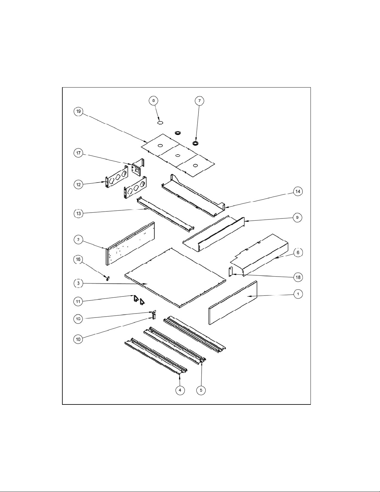
Cabinet Drawing E
L22-333, rev. 0 (3/11)
Page 14

SECTION F: Elements, Upper Heat Shield, and Cabinet Backs
Elements, Upper Heat Shield, and Cabinet Backs Drawing F Parts List
QUANTITY
P/N DESCRIPTION
MKE24
MKE36
MKE48
MKE60
ITEM #
5125-1555101-C ELEMENT, CLAMP FRONT E-TSTAT 10" 23456
1 5125-1555102-C ELEMENT, CLAMP PLATE FRONT 10" 23456 234
5125-1555103-C ELEMENT, CLAMP PLATE 10" 4 6 8 10 12 4 6 8 10 12 4 6 8
5125-1554604-C ELEMENT, CLAMP PLATE FRONT 7" 1 1 1
5125-1554608-C ELEMENT, CLAMP PLATE 7" 2 2 2
50007601 ELEMENT, FB MKE 208V 10" 1900W 6 9 12 15 18 6 9 12 15 18 6 9 12
50007602 ELEMENT, FB MKE 240V 10" 1900W 6 9 12 15 18 6 9 12 15 18 6 9 12
2
50007701 ELEMENT, FB MKE 208V 7" 1425W 3 3 3
50007702 ELEMENT, FB MKE 240V " 1425W 3 3 3
5425-1554701-C ELEMENT, CLAMP STRAP 10" 12 18 24 30 36 12 18 24 30 36 12 18 24
3
5425-1554703-C ELEMENT, CLAMP STRAP 7" 6 6 6
5425-1555201-C HEAT SHIELD, UPPER STANDARD 2345623456123
4
5425-1555203-C HEAT SHIELD, UPPER LH TROUGH 1 1 1
5425-1555301-C HEAT SHIELD, UPPER GAP STANDARD 1234 1234123
5
5425-1555303-C HEAT SHIELD, UPPER GAP LH 1111111111
5425-1555305-C HEAT SHIELD, UPPER GAP LH TRH 1 1 1
6 60141102 PROBE, RTD 1K DIN 13" MKE 23456 345
7 A1847501 CABINET, BRACKET POWER CORD 2244422444244
5425-1554901-C HEAT SHIELD, UPPER SUPPORT FRONT 24 1 1
5425-1554903-C HEAT SHIELD, UPPER SUPPORT FRONT 36 1 1 1
8
5425-1554905-C HEAT SHIELD, UPPER SUPPORT FRONT 48 1 1 1
5425-1554907-C HEAT SHIELD, UPPER SUPPORT FRONT 60 1 1 1
5425-1554909-C HEAT SHIELD, UPPER SUPPORT FRONT 72 1 1
5425-1554911-C HEAT SHIELD, UPPER SUPPORT REAR 24 1 1
5425-1554913-C HEAT SHIELD, UPPER SUPPORT REAR 36 1 1 1
9
5425-1554915-C HEAT SHIELD, UPPER SUPPORT REAR 48 1 1 1
5425-1554917-C HEAT SHIELD, UPPER SUPPORT REAR 60 1 1 1
5425-1554919-C HEAT SHIELD, UPPER SUPPORT REAR 72 1 1
5425-1553901-C CABINET BACK, UPPER 24 1 1
5425-1553903-C CABINET BACK, UPPER 36 1 1 1
10
5425-1553905-C CABINET BACK, UPPER 48 1 1 1
5425-1553907-C CABINET BACK, UPPER 60 1 1 1
5425-1553909-C CABINET BACK, UPPER 72 1 1
5425-1555501-C CABINET BACK, LOWER 24 1 1
5425-1555503-C CABINET BACK, LOWER 36 1 1 1
11
5425-1555505-C CABINET BACK, LOWER 48 1 1 1
5425-1555507-C CABINET BACK, LOWER 60 1 1 1
5425-1555509-C CABINET BACK, LOWER 72 1 1
5425-1555601-C CABINET BACK, MIDDLE 24 1 1
5425-1555603-C CABINET BACK, MIDDLE 36 1 1 1
12
5425-1555605-C CABINET BACK, MIDDLE 48 1 1 1
5425-1555607-C CABINET BACK, MIDDLE 60 1 1 1
5425-1555609-C CABINET BACK, MIDDLE 72 1 1
13 5425-1556301-C CABINET BACK, UPPER SPACER 1111111111111
MKE72
MKE24 E-TSTAT
MKE36 E-TSTAT
MKE48 E-TSTAT
MKE60 E-TSTAT
FG-MKE36
MKE72 E-TSTAT
FG-MKE48
FG-MKE60
L22-333, rev. 0 (3/11)
Page 15

Elements, Upper Heat Shield, and Cabinet Backs Drawing F
L22-333, rev. 0 (3/11)
Page 16

In the event of problems with or questions
about your order, please contact the
MagiKitch’n factory at:
(800) 258-3708 US and Canada only
(603) 225-6684 World Wide
www.magikitchn.com
MAILING ADDRESS – P.O. BOX 501, CONCORD, NH 03302-0501
SHIPPING ADDRESS – 10 FERRY ST., CONCORD, NH 03301
L22-333, rev. 0 (3/11)
In the event of problems with or questions
about your equipment, please contact the
MagiKitch’n Authorized Service and Parts
representative (ASAP) covering your area,
or contact MagiKitch’n at the numbers
listed to the left.
 Loading...