

Page 1
IMPORTANT FOR FUTURE REFERENCE
Please complete this information and retain this manual
for the life of the equipment:
Model #: __________________________
Serial #: __________________________
Date Purchased: ___________________
Service Manual
MKE: MagiKitch’n Electric Griddle
March 2011
L22-334, rev. 0 (3/11)
Page 2

MKE SERVICE MANUAL
WARNING
DO NOT store or use gasoline or other flammable
vapors and liquids in the vicinity of this or any
other appliance.
WARNING
Improper installation, alteration, service or
maintenance can cause property damage, injury
or death. Read the installation, operating and
maintenance instructions thoroughly before
installing or servicing this appliance.
WARNING
Installation, maintenance and repairs should be
performed by a MagiKitch’n Authorized Service
and Parts (ASAP) company technician or other
qualified personnel. Installation, maintenance or
repairs by an unauthorized and unqualified
personnel will void the warranty.
WARNING
Installation and all connections must be made
according to national and local regulations and
codes in force.
WARNING
A country approved all pole circuit breaker with a
minimum open contact gap of 3mm must be used
for proper installation. (CE countries)
WARNING
During the warranty period if a customer elects to
use a non-original part or modifies an original part
purchased from MagiKitch’n and/or its Authorized
Service and Parts (ASAP) companies, this
warranty will be void. In addition, MagiKitch’n
and its affiliates will not be liable for any claims,
damages or expenses incurred by the customer
which arises directly or indirectly, in whole or in
part, due to the installation of any modified part
and/or received from an unauthorized service
center.
WARNING
This appliance, when installed, must be
electrically grounded in accordance with local
codes, or in the absence of local codes, with the
National Electrical Code, ANSI/NFPA 70, or the
Canadian Electrical Code, CSA C22.2, as
applicable.
WARNING
Adequate means must be provided to LIMIT the
movement or this appliance without depending on
the electrical cord connection. Single appliances
equipped with legs must be stabilized by
installing anchor straps. All appliances equipped
with casters must be stabilized by installing
restraining chains.
WARNING
DO NOT alter or remove structural material on the
appliance to accommodate placement under a
ventilation hood.
WARNING
This appliance is intended for professional use
only and should be operated by fully trained and
qualified personnel.
WARNING
If the supplied power cord is damaged, it must be
replaced by a MagiKitch’n Authorized Service and
Parts (ASAP) company technician, or a similarly
qualified person in order to avoid a hazard.
WARNING
The power supply must be disconnected before
servicing, maintaining or cleaning this appliance.
WARNING
The appliance is NOT jet stream approved. DO
NOT clean the appliance with a water jet.
WARNING
DO NOT attempt to move this appliance or
transfer hot liquids from one container to another
when the unit is at operating temperature or filled
with hot liquids. Serious personal injury could
result if skin comes in contact with the hot
surfaces or liquids.
WARNING
DO NOT sit or stand on this appliance. The appliance’s
front panel, cook plate, splash back, side, workshelf not
a step. Serious injury could result from slipping, falling
or contact with hot surfaces or liquids.
WARNING
NEVER use the appliance as a step for cleaning or
accessing the ventilation hood. Serious injury could
result from slips, trips or from contacting hot surfaces
or liquids.
WARNING
DO NOT use the appliance unless it is properly secured
to a table, stand or freezer / refrigerated base suited to
handle the weight of the entire appliance.
WARNING
DO NOT operate appliance unless all panels and
access covers are attached correctly.
WARNING
It is recommended that this appliance be
inspected by a qualified service technician for
proper performance and operation on a yearly
basis.
L22-334, rev. 0 (3/11)
Page 3

MKE SERVICE MANUAL
TROUBLE SHOOTING.............................................................................3
Problems and Possible Causes .........................................................................................................3
Normal Operating Component Properties ........................................................................................4
FRONT AND REAR PANELS...................................................................4
Removal of Front Panels and Access to Component Panels.........................................................4
Assembly of Front Panels...................................................................................................................5
Rear Panels ..........................................................................................................................................6
COMPONENT PANELS............................................................................7
Component Location...........................................................................................................................7
Component Replacement ...................................................................................................................7
1. Contactors ................................................................................................................................................7
2. Cord and Plug Sets..................................................................................................................................8
3. Fuses.........................................................................................................................................................8
4. Relays (Electric Thermostats Only)........................................................................................................8
5. Switches....................................................................................................................................................8
6. Thermostats.............................................................................................................................................. 8
7. Transformers............................................................................................................................................9
ELEMENTS AND PROBES....................................................................10
Location and Numbering ..................................................................................................................10
Replacing an Element .......................................................................................................................11
Replacing a Probe .............................................................................................................................12
THERMOSTAT CALIBRATION..............................................................14
Electric Thermostat ...........................................................................................................................14
Solid State Thermostat......................................................................................................................14
L22-334, rev. 0 (3/11)
Page 4
Trouble Shooting
r
MKE SERVICE MANUAL
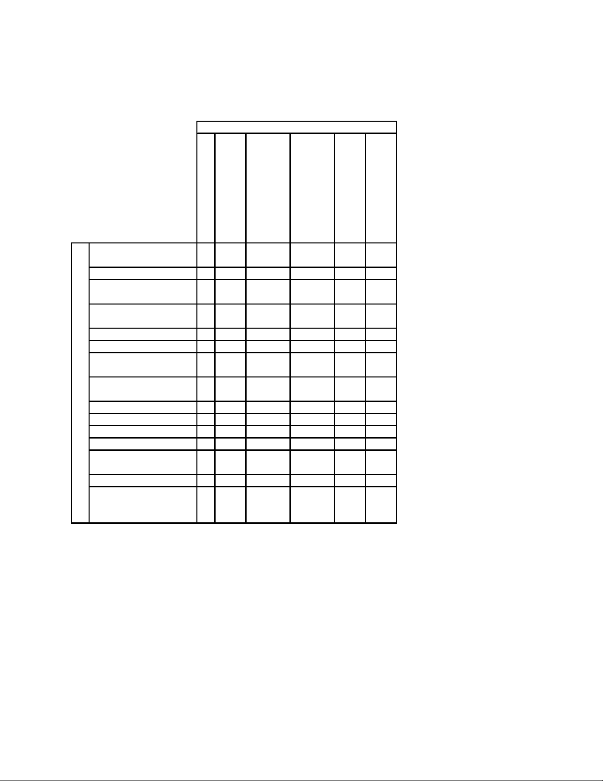
Problems and Possible Causes
PROBLEM
turn on
Zone is not heating
Switch light does not
Griddle is not plugged
in (if so equipped)
Power switch is off X X
Thermostat is set to
"OFF"
Thermostat is not
calibrated
Thermostat failure X X X
Transformer failure X X
Wire harness is
disconnected
Relay failure
(if equipped)
Probe Failure X X X X
Element Failure X X X
POSSIBLE CAUSE
Switch failure X X
Contactor failure X X
Wrong voltage tab on
transforme
Snubber failure X
Diode in Switch Circuit
has been Wired
Backwards
XX
X
XX X
XX
X
to zone
Plate temperature is
inconsistent from zone
XX
Griddle temperature is
inconsistent in one zone
overheats
Griddle stays hot or
Contactor is chattering
X
L22-334, rev. 0 (3/11)
Page 5
MKE SERVICE MANUAL
Normal Operating Component Properties
Property
Normal Re sistance
(OH MS)(A p p ro x im ate)
Relay Coil Check for Continuity
Contactor Coil 5.8 - 7.0
10" Element Check for Continuity
7" Element Check for Continuity
Solid State Relay C oil Che ck fo r Contin u ity
Component
Solid State Probe
Electric Ts ta t c o il Ch e ck fo r C ontinu ity
Transformer Check for Continuity
Fuse Check for Continuity
1466 at 250F
1680 at 250F
1894 at 250F
Front and Rear Panels
Removal of Front Panels and Access to Component Panels
Always use caution when removing any of the front panels as live contacts are inside at 24VAC
as well as the line voltage. It is highly recommended to turn off power to the unit at the circuit breaker or
unplug the unit before removing any of the front panels.
The first step to removing any of the front panels is to remove the grease drawer(s). Always
check the grease level in the drawer by slowly pulling the drawer forward. If the Unit has been in
operation recently this grease may be hot. Set aside.
The two lower front panels will be next.
There are two types of lower front panels: those
next to the cabinet wall and those next to a
grease drawer enclosure. Both types require
the removal of two phillips head screws next to
the controller panel. Once the screws are
removed the panels may spring forward on the
controller panel side. The lower front panel next
to a grease drawer enclosure is removed by
pulling the controller panel side toward you then
moved toward the grease drawer to remove it’s
tab from a slot in the grease drawer enclosure.
Set aside.
2
The lower front panel next to the
cabinet wall is very similar except the tab / slot
is reversed. After removing the two retaining screws at the controller panel, pull the lower front panel
toward you, then move it towards the controller panel. This removes a tab attached to the cabinet wall
from a slot in the lower front panel. Set aside.
L22-334, rev. 0 (3/11)
Page 6

MKE SERVICE MANUAL
At this point, wires may be visible in the two openings where the lower front panels once were. It
is recommended that servicing the unit is not attempted through these openings as visibility is poor.
Remove at least the switch panel.
Remove the switch
panel by first removing the
screws above the switches.
The screws will have 5/16 hex
heads. Once the screws are
removed the may drop so
support the panel as the last
screws are removed. The
panel can then be pulled
down and toward you. The
panel is still connected to the
controller circuit. There will
be one Molex connector per
switch. Remaining on the panel will be the switches, and small harnesses terminating in the pin side of
the Molex connectors. This harness contains the diode for the LED light in each of the switches. The
Diode will be covered in heat shrink tubing. If this is not the subject of service, set aside.
The majority of the electrical components can now be seen inside this cavity. Further access
space to the top of the cavity can be made by removing the switch panel retention bracket, which runs the
width of the unit near the top of the unit. To remove, support the bracket and remove a series of screws
whose heads now face you down the length of the bracket. When the screws are removed the bracket
will fall if not supported. Set Aside.
SCREWS
Assembly of Front Panels
Be sure that all components are in place and wires have been properly dressed and are out of the
way. If the controls panel is not in place, do so now.
Place the switch panel retention bracket at the top, front of the component heat shield and align
the mount holes. Secure with screws starting from the center and working out from there.
Reconnect the switch panel to its mating Molex connectors in each control circuit. Be sure that
the zone 1 controller is connected to the zone 1 switch and so on. Also be sure that the wire number,
configuration, and colors match from one side of the Molex union to the other.
The lower left and right corners of the switch panel hook around mounting brackets on the insid e
of the cabinet walls. Check for wires around the controls panel and above the grease drawer
enclosure(s). Grooves in the bottom edge of the switch panel match up with the grease drawer
enclosure(s) and the two sides of the controls panel. The switch panel then tips forward until it contacts
the retention bracket. Secure with screws.
The lower front panels install just as they are removed. The tab of the lower panel hooks into the
slot of the grease drawer enclosure(s) and swings into place. The slot of the other lower front panel
mates to a tab mounted to the inside of the cabinet side. Then it swings into place. Both lower front
panels have flanges that lap over one side of the controls panel and is secured with two screws.
Slide the grease drawer(s) into its enclosure.
L22-334, rev. 0 (3/11)
Page 7

MKE SERVICE MANUAL
Rear Panels
The rear panels are broken up into three sections: Upper, Middle, and Lower. To rem ove the
Upper or Middle panels, remove the screws or bolts securing them. The panel will then come free, set
aside. The lower panel contains removable brackets around the power cord(s). By loosening the upper
screw(s) and removing the lower screw(s)
the lower bracket may be swung out of
the way. Then remove the screws
securing the panel to the griddle and the
panel will come free.
To put a panel back on the
griddle, reposition it on the griddle and
secure with the screws or bolts previously
removed. The Middle and Lower panels
have a top edge that sits on the inside of
the mating edge of the panel above it.
When securing the Lower panel, swing
the lower cord bracket around the cord
and tighten both screws.
LOWER PANEL
UPPER PANEL
MIDDLE PANEL
LOOSEN
REMOVE
L22-334, rev. 0 (3/11)
Page 8

MKE SERVICE MANUAL
Component Panels
Component Location
To gain access to the component panels remove front panels, see FRONT AND REAR PANELS
section.
MKE36 with Solid State Controls
ZONE 1 ZONE 2 ZONE 3
ZONE1 ZONE 2 ZONE 3
ZONE 1 ZONE 2 ZONE 3
1. Transformers: one for each 12” zone of griddle. The left most transformer will power the 24 volt AC
control circuit for the left most 12” zone of griddle, “Zone 1”, and so on.
2. Terminal Block: one per cord. This will power 2 or 3 zones of griddle. There will be one or two
terminal blocks per griddle depending on the size (MKE24-36: one terminal block, MKE48-72 two terminal
blocks).
3. Controller panel: mounting panel for the griddle’s temperature controllers. The panel is held in
place with four screws.
4. Fuse Blocks and Fuses: Six fuses are used for each cord/ terminal block.
5. Contactors: one for each 12” zone of griddle. The left most contactor will operate three elements in
the left most 12” zone of griddle, “Zone 1”, and so on.
Component Replacement
1. Contactors
Each contactor will be connected to 6 wires,
three upper wires and three lower wires. The top
wires are from the fuse block. The lower wires are the
second of two leads from that zone’s three elements.
Each of the wires should be labeled according to what
they attach to. For example: on the contactor all of the
way to the left will be for zone 1. The lower wires will
be labeled 1 L-2, 2 L-2, and 3 L-2 from left to right.
These are leg 2 of element 1, 2, and 3. The upper
wires will be labeled by what fuse they go to. The best
practice is to transfer one wire at a time from the
contactor to be removed to the same location on the
contactor to be installed. Then remove the two screws
securing the old contactor to the component panel and
replace it with the fully wired new contactor.
SCREWS
L22-334, rev. 0 (3/11)
Page 9

MKE SERVICE MANUAL
2. Cord and Plug Sets
Each cord is secured to the griddle at two points: the terminal block in the front of the griddle and
the strain relief in the rear. Both front and rear panels
need to be removed to install, change, or remove a
cord. See the Front and Rear panel section for proper
removal. In the front of the unit, disconnect the cord
from the terminal block with the appropriate allen
wrench and from the ground lug with a flat tip
screwdriver. From the rear of the griddle the griddle
the strain relief may be loosened or the assembly can
be freed as a whole by removing four screws near the
cord. The cord is removed from the strain relief by
unthreading two retaining collars.
To install a cord, thread it through the strain
relief, the sheet metal retainer, then the plastic
retainer. Tighten both retainers. Reinstall the cord
into the terminal block and the ground wire to the
ground lug below the terminal block at the front of the
unit.
3. Fuses
Fuses are item #4 the component location diagram. To remove, pull the fuse away from the
block. To install a new fuse, place on contacts of the fuse block and press the metallic ends firmly into
place. Fuse will snap into place when correctly installed.
4. Relays (Electric Thermostats Only)
Relays are located above and/or below the grommets in the component panel(s). The best
practice is to transfer one wire at a time from the old relay to the new one. The relay can then be
removed by removing two screws. Replace new relay with screws.
5. Switches
All switches are located in the Switch panel. See the Front and Rear Panels section for removal
instructions. Once the panel is removed and the Molex connectors are disconnected the switch and a
small wire harness are all that remain on the panel. The wire harness must be removed from the switch
first as it cannot fit through the cutout in the panel. The switched circuits are between tabs 2 and 3, and 5
and 6. In this application only one set is used. The leads going to the other tabs are to power the LED
lamp in the switch. It is important to note that tab 8 is the positive tab and tab 7 is the negative tab. Tab
8 will be connected to the red lead with the heat shrink tubing on it. This tubing contains a diode to keep
the lamp from flickering.
To remove a switch press the thin plastic flaps at the top and bottom of the switch in toward each
other. While holding the flaps, the switch can be passed through the opening in the panel toward the
rocker side of the switch.
To install a new switch, first orient the switch so that the lamp lens and “I” marking are at the top
relative to the switch panel. Then pass the switch through the cut out in the switch panel and press it
firmly into place. Thin plastic flaps at the top and bottom of the switch should spring away from the switch
locking it in place. Reconnect the harness to the switch as described above.
6. Thermostats
Thermostats are located in the Controls Panel at the lower front of the griddle. A solid state
thermostats is connected by quick disconnect to a probe mounted with the front row of elements. This
type may be replaced independent of the probe. Electric thermostats are directly connected to a sensory
bulb by a capillary, which must all be replaced as a unit. If replacing an electric thermostat see the
Elements and Probes section for probe removal instructions.
The Controls panel may be removed from the griddle before preceding. The first step to
changing a thermostat is to remove the knob. To remove the knob of an electronic thermostat, pull it
towards you and it should slip off a central shaft. The solid state thermostat knob is held in place by a
collet. Start by removing the knob face, which is a round disk with a white line on it. This can be done
with a fingernail or a thin screwdriver. A brass collet inside the knob is now visible. Loosen the nut to
release the knob from its shaft. Do not completely remove the nut from the collet. Then pull the knob
towards you to remove.
RETAINERS
SCREWS
L22-334, rev. 0 (3/11)
Page 10

MKE SERVICE MANUAL
Both types to thermostats are secured to the Controls Panel with two small screws. Remove the
thermostat and transfer the leads to the new one. Secure the new thermostat to the Controls Panel using
the screws and reattach the knobs.
See the Calibration section to calibrate all new thermostats.
7. Transformers
Transformers are located in the upper section of the component cavity. The one powering zone 1
control circuit is on the left, then there is zone 2 to right of that and so on.
To change a transformer, remove the two screws securing it to the component heat shi eld.
Transfer the leads from the old one to the new one, and secure the new one in the old one’s pl ace using
the two screws.
L22-334, rev. 0 (3/11)
Page 11

MKE SERVICE MANUAL
Elements and Probes
Location and Numbering
Shown is the element layout of an MKE36 as seen from under the plate. The elements are numbered
from front to rear and left to right as seen below. For larger units the numbering pattern continues in the
same way. Each element is contained by an element pan. Each element pan is held in place by two
straps. The strap pairs are actually two of the same strap with one reversed. Each strap is secured with
two Grade 8 ¼-20 x 5/8 bolts through two washers. Do not replace the supplied bolts with lesser or nonrated bolts. The elements have two lead wires. The wires are labeled with the element number and the
leg number, leg one or leg two. The difference is that leg one is wired to the fuse block and leg two is
wired to a contactor.
LEFT
PAN
PROBE
1
2
3
FRONT
4
5
6
REAR
STRAP
7
RIGHT
8
9
L22-334, rev. 0 (3/11)
Page 12

MKE SERVICE MANUAL
Replacing an Element
See the Front and Rear panel section to remove all front panels. If replacing a rear element also
remove all of the rear panels.
If removing a front or middle row element then the heat shield that the transformers and fuse
blocks are attached to must now be removed.
The individual components can be removed from
the heat shield to avoid unwiring them, or they
can all be unwired, left on the panel and removed
as one.
The component heat shield attaches to a
bracket on the grease trough side and the cabinet
wall on the side without grease trough where
applicable. Support the heat shield as you
remove the screws retaining it. The assembly
can now be removed from the griddle.
The element to be replaced will need to
be unwired at two points: the Fuse Block (leg 1)
and the contactor (leg 2) for the zone the element
is in. Refer to the photograph in the previous
section to determine the element number. The leads of the element will be labeled with this number as
well as a leg number.
At least one side of the upper heat shield,
front or rear needs to be lowered to access the
elements. Remove all of the screws along the
support to be lowered being sure to prevent the
heat shields from dropping. The heat shield
panels associated with the element to be
changed need to be removed to properly route
the wires. Each heat shield panel to be removed
can be pulled toward you and out of the griddle.
Note: the panel will drop off of the support on the
other side of the griddle when it is pulled out. Use
caution not to rub a sheet metal edge on an
element lead wire when the panel is being
removed.
The element will be secured with 4 bolts
or 6 bolts if it is zone 1 of a Left-Hand Trough
griddle. You will most likely need a 7/16 socket
and ratchet to remove the bolts. Note: as you
remove all of the bolts supporting a strap it will
come free. As you remove the last bolt, support
the element pan to prevent it from dropping on
your arm. The element and pan can now be
removed from the griddle. If removing an element
in the first row, in the front of the griddle, see the
Replacing a Probe section. Note: Solid state
probes may be left in place when replacing the
associated element. The element leads will need
to be pulled through the grommet in the contactor
panel and the grommet in the middle heat shield.
Remove the element from the pan.
To install a new element, first place the
new element into the element pan by threading
the leads through the appropriate cutout (there
may be more than one). Use caution not to rub
PANELS
SCREWS
SUPPORT
L22-334, rev. 0 (3/11)
Page 13

MKE SERVICE MANUAL
the element leads on the edge of the cutout. Seat
the element in the pan. Some manipulation of the
element may be necessary to get to sit flat in the
pan. Route the leads through the middle heat
shield grommet and the contactor panel grommet
where the old element was removed. The
contactor panel may need to be pivoted to do this.
To pivot the contactor panel, remove all of the
screws along to top edge. Pull on the right side to
let the panel pivot on the cord connection to the
terminal block. Reconnect the leads and secure
the contactor panel with its screws.
Place the element and pan in its position
on the underside of the griddle plate. If replacing
a front element, be sure that the grooved tab in
the element pan supports the probe sheath or the
capillary. While holding it in place secure a strap
to the pan with a bolt and washer. Thread and tighten the remainder of the bolts with washers. Note:
only tighten each bolt to 35 inch-pounds or 3 footpounds torque. Always verify that the element is
sitting flush with the griddle plate. There should
be a .020 to .040 gap between the underside of
the griddle plate and the element pan. A mirror
may be necessary to observe this. It is possible
for an element pane to be too close to the
perimeter of the griddle and get hung up on the
weld bead in this area. If this occurs, loosen the
four bolts for the affected element and slide it off
of the weld bead and retighten the bolts.
The upper heat shield must now be put
back in place. The notch in the upper heat shield
is positioned toward the front side of the griddle.
Then slide the panel into the griddle below the
elements and above the middle heat shield. The
first edge into the griddle must be lifted onto the
ledge of the opposite support bracket. Note: as each panel is slid into position, do not rub any wires on
the sheet metal edges. Now the panel should have its far edge supported by the opposite support
bracket and the near edge resting on the support bracket that was previously removed. The probe
sheath or capillary should be positioned to pass through the notch in the panel on the front side of the
griddle. The smaller panels fit between the larger panels next to the vertical legs of the elements. It may
be necessary to insert them with their short edge vertical and twist them flat once in position. As always,
be careful not to rub the sheet metal edges on any wires when inserting a heat shield panel into the
griddle. They are supported on the support brackets the same way the larger panels are. Once all panels
are in place, there will not be any open spaces in the heat shield layer, lift the support bracket and all of
the heat shield panels into place. Be careful not to catch the small vertical flanges of the panels on the
element legs or the cabinet sides. Secure the bracket with the center screw first, then secure the others.
The component heat shield must now be lifted back into position and secured on the left and right
sides with screws. If removed, all components must be secured to the panel and any disconnected
connectors reconnected.
PROBE
NOTCH
Replacing a Probe
Remove the front element associated with the probe from the griddle plate per instructions listed
in the previous section. Keep the element in the pan and do not unwire it.
Solid State Probe: Disconnect the probe from the thermostat. Pull the probe toward you until it
reached the metal plate as shown. Then tip the metal sheath to one side or the other until it is parallel
with the floor. The probe will want to move in the opposite direction that you are tipping it. Now the probe
can be pulled down at the bend to clear the sheet metal edge. Pull the probe straight toward you and out
L22-334, rev. 0 (3/11)
Page 14

MKE SERVICE MANUAL
of the griddle. Remove the leads from the cutout in the element pan. Thread the new element leads
through the cutout being careful not to rub the leads on the edge of the cutout. Insert the tip of the new
probe into the slot in the griddle plate where the old probe came out of. At the end of the slot there is a
drilled whole for the probe. Insert the probe into the
hole with the last leg of the probe sheath parallel to
the floor. Rotate the leg to be perpendicular to the
floor and push it forward into the griddle plate until
it stops. Reattach the element.
Electric Thermostat Probe: Once the
element has been dropped, the bulb can be fed
through the cutout on the element pan and
removed. Thread the new bulb through the cutout
and place in the center of the cradle. While
reattaching the element to the griddle, use caution
to keep the bulb in the center of the cradle and not
to damage the capillary.
L22-334, rev. 0 (3/11)
Page 15

MKE SERVICE MANUAL
Thermostat Calibration
Each control operates a set of three elements. The controls were set at the factory. However, if the
griddle’s surface temperature varies greatly from the setting on the thermostat knob, adjust the thermostat
using the following procedure:
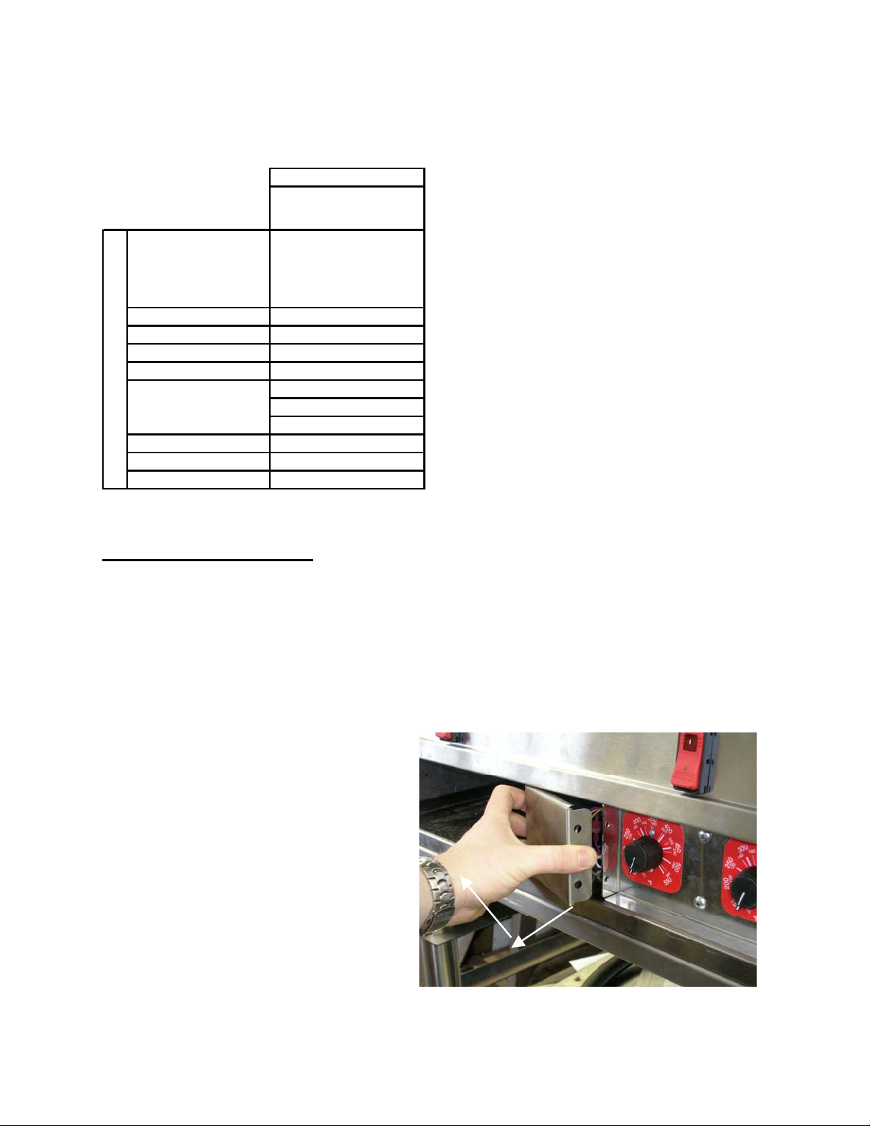
Electric Thermostat
1. Turn all the control knobs to the
desired temperature setting.
2. Wait 30 minutes (or 1 hour if
griddle was cold) for surface to
stabilize.
3. Place a reliable Griddle surface
thermometer,
or test instrument
thermocouple, (able to register
300°F), in the location above the
REMOVED, SNAP ACTION
thermostat being calibrated as
described in section 2.2.2. Check
the temperature every 5 minutes
until the temperature stabilizes
and does not change by more
than 30°F over a 15 minute span.
4. If the average temperature over
any burner set is not within +/-15°F of the knob setting (300°F), adjust the corresponding
thermostat. This is done by removing the knob, holding the thermostat knob stem, see picture
above, (do not allow the stem to turn or the temperature setting will not be accurate), then
turn the adjustment screw located within the center of the stem in small increments. Turn this
screw counter clockwise to increase the temperature, and clockwise to decrease the temperature.
5. Check the temperature after 15 minutes and repeat adjustment as needed until the correct
temperature is indication on the measuring instrument.
THERMOSTAT ADJUSTMENT SCREW
TURN CW TO DECREASE TEMPERATURE
TURN CCW TO INCREASE TEMPERATURE
THERMOSTAT KNOB
THERMOSTAT STEM
ELECTRIC THERMOSTATS SHOWN FOR REFERENCE
Figure 1
NOTICE
The adjustment screw on the thermostat is sealed by the Manufacturer to protect the calibration. It
may be necessary to remove this seal to be able to adjust the thermostat.
Solid State Thermostat
1. Turn all the control knobs to the
desired temperature setting.
2. Wait 30 minutes (or 1 hour if griddle
was cold) for surface to stabilize.
ALIGNED WITH ACTUAL TEMP.
THIS CAP SNAPS
ON AND OFF
ROTATE KNOB UNTIL
TEMP. INDICATOR IS
5/16" NUT
3. Place a reliable Grill surface
thermometer,
or test instrument
thermocouple, (able to register
300°F), In the location above the
thermostat being calibrated
described in section 2.2.2. Check
the temperature every 5 minutes
until the temperature stabilizes and
350
4
1
8
0
0
0
0
2
6
0
3
0
4
1
0
0
5
2
2
1
0
0
0
1
0
2
8
0
1
5
0
0
1
0
0
2
2
4
0
5
0
2
4
0
5
2
6
0
0
0
0
8
2
0
5
°
C
5
°F
Figure 2
350
4
1
8
0
0
0
0
2
6
0
3
0
4
1
0
0
5
2
2
1
0
0
0
1
0
2
8
0
1
5
0
0
1
0
0
2
2
4
0
5
0
2
4
0
CAP LINE
5
2
6
0
0
0
0
8
2
0
5
°
C
5
°F
does not change by more than 30°F
over a 15 minute time period. You will need to remember the average temperature for the next
step.
4. Carefully remove the cap on the thermostat knob with the white indicator line see picture this
section. While holding the knob, loosen the 5/16" nut on the thermostat shaft, (DO NOT
REMOVE), once the nut is loose the knob can be rotated so that the cap line marker is aligned
with the actual temperature that the Grill surface thermometer is indicating.
Re-tighten the 5/16" nut while holding the knob in position, (do not allow the stem to turn or the
temperature setting will not be accurate). Replace cap
L22-334, rev. 0 (3/11)
Page 16

MKE SERVICE MANUAL
In the event of problems with or questions
about your order, please contact the
MagiKitch’n factory at:
(800) 258-3708 US and Canada only
(603) 225-6684 World Wide
www.magikitchn.com
MAILING ADDRESS – P.O. BOX 501, CONCORD, NH 03302-0501
SHIPPING ADDRESS – 10 FERRY ST., CONCORD, NH 03301
L22-334, rev. 0 (3/11)
In the event of problems with or questions
about your equipment, please contact the
MagiKitch’n Authorized Service and Parts
representative (ASAP) covering your area,
or contact MagiKitch’n at the numbers
listed to the left.
 Loading...