

Page 1
Cater
T
WARNING
Cater Thermocouple
Service Quick Reference Card
MagiCater Model LPCE
Thermocouple Replacement Instruction
Technical Service Replacement & Set Up Instructions
Please read complete instructions prior to starting.
RETAIN THESE INSTRUCTIONS FOR FUTURE REFERENCE
WARNING
This procedure should be performed by a qualified service agency in
accordance with the manufacturer's instructions and all applicable codes
and requirements of the authority having jurisdiction. If the information in
these instructions is not followed exactly, property damage, personal
injury or loss of life may result. The qualified service agency is
responsible for the proper installation of the parts and assembly. This
replacement procedure is not proper and complete until the operation of
the appliance is checked as specified in the manufacturer's instructions.
Ensure that the gas supply to this appliance is turned off and
disconnected before performing this procedure.
WARNING
Use only parts supplied with the parts kit, or existing parts on the
appliance as directed. Use of any parts other than those supplied will
void the warranty and could cause unsafe conditions or improper
operation of your appliance.
WARNING
Ensure that appliance has cooled to room temperature before performing
this procedure. DO NOT work on a hot appliance; serious personal injury
may occur.
WARNING
Adequate means must be provided to limit the movement of this
appliance without depending on the gas line connection. If any
restraining devices are disconnected during this procedure, ensure that
they are reconnected before putting the appliance into service. Failure to
do so could result in a dangerous and unsafe condition.
1 L80-108 Rev 1, (11/12)
Page 2
Cater Thermocouple
Service Quick Reference Card
NOTE: If you have any questions about this procedure please call
Pitco at (603) 225-6684 and ask for the Technical Service department.
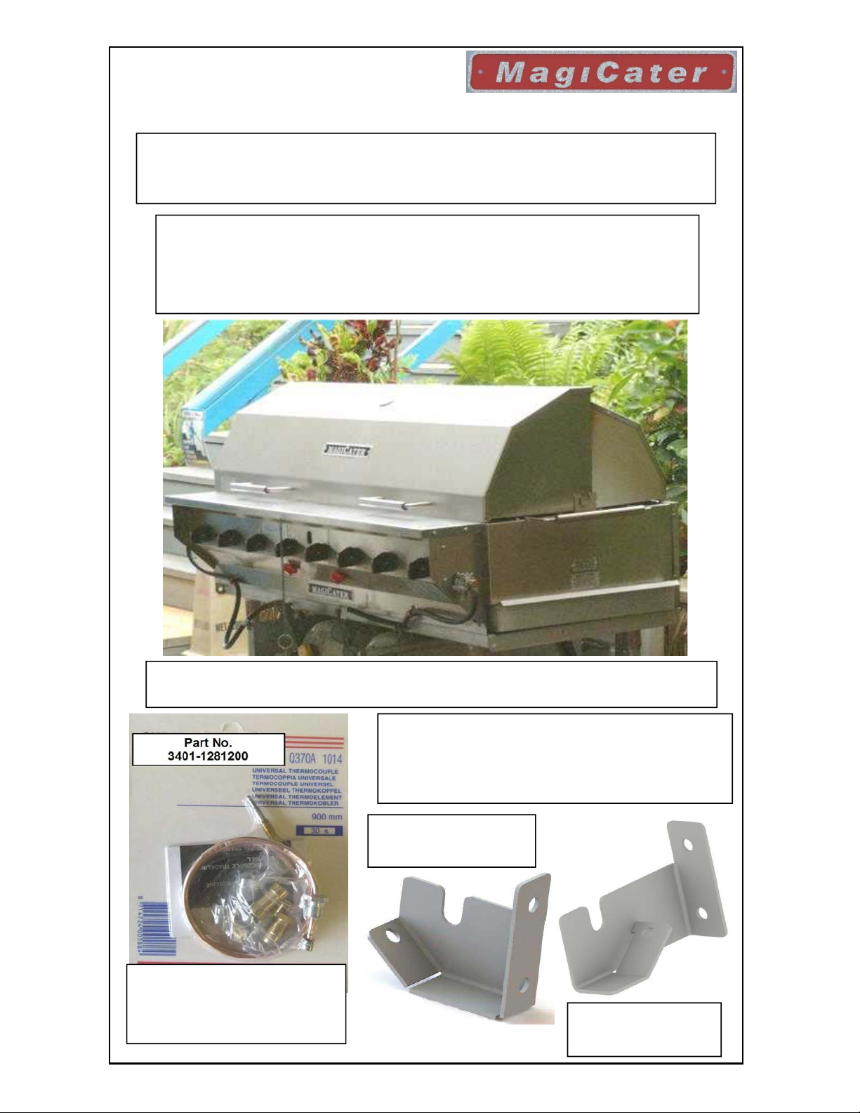
Follow these steps to replace the Safety Pilot Thermocouple, Part
No. 3401-0996200 with 3401-1281200.This procedure should be
performed by an Authorized Service Agency.
MODEL SHOWN ABOVE MAY INCLUDE OPTIONS OR
ACCESSORIES NOT INCLUDED ON ALL MODELS.
1- Part No.
3401-1281200
Packaging m ay Vary
Upgrade Parts Included
1- Thermocouple, CE Cater
2- Bracket, Left Hand Thermocouple
3- Bracket, Right hand Thermocouple
2- Part No.
5125-1562701
3- Part No.
5125-1562702
2 L80-108 Rev 1, (11/12)
Page 3
Cater Thermocouple
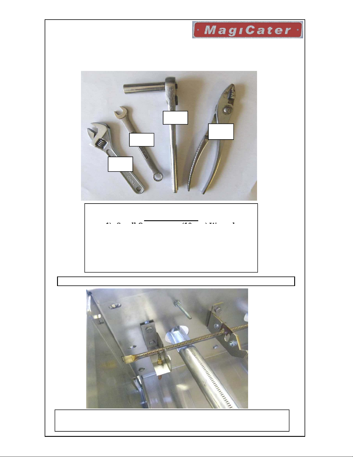
1)-Small
C
(10
h
Service Quick Reference Card
Tools Required for this Upgrade
2
1
3
4
Tool Legend
rescent or
2)- 7/16" (12mm)Wrench
3)- 7/16" (12mm) Deep Well Socket
4)- Small Pair of Universal Pliers
5)- Fluropolymer ThreadTape,(NotShown)
Thermocouple Upgrade replacement Instructions
mm) Wrenc
Step 1- Remove Top grids, Panels, Radiants or Coal Screens to gain
access to the Thermocouple to be replaced.
3 L80-108 Rev 1, (11/12)
Page 4

Cater Thermocouple
removed from the
Service Quick Reference Card
Step 3 -
With the thermocouple
bracket, locate and
remove the two (2) 7/16"
(12mm) nuts and bolts
that mount the bracket to
the cabinet frame.
Step 2-
Locate the retaining nut
at the base of the
thermocouple. Using the
universal pair of pliers
loosen and remove the
nut to free the
thermocouple from the
existing bracket.
4 L80-108 Rev 1, (11/12)
Step 3a -
Remove remaining nut
and bolt, one bolt shown
removed for reference.
Remove old bracket(s)
and discard, The nuts and
bolts removed will be
reused to install the new
bracket(s).
Page 5

Cater Thermocouple
Service Quick Reference Card
Step 4 -
Locate the gas safety
valve and loosen and
remove the thermocouple
lead from the valve using
the small crescent, or
10mm wrench.
Step 5 -
Mount the new
thermocouple bracket in
the same mounting holes,
using the same nuts and
bolts from the old
bracket. There is a left
and right bracket, see step
6 for bracket to runner
tube orientation.
Step 6 -
The new bracket is
installed correctly if the
thermocouple mounting
hole (A), is facing the
ports (B) of the existing
runner tube. See photo at
right.
5 L80-108 Rev 1, (11/12)
Page 6

Cater Thermocouple
Slide the spacer (C)
Service Quick Reference Card
Step 7 NOTE -
Some Safety Valves may appear
different from the one shown above.
Step 7 -
Unwrap the new
thermocouple and attach
the lead to the safety
valve. Use the small
crescent wrench or
10mm wrench to tighten
the nut into the valve.
Route the thermocouple
tip through the cabinet to
the mounting bracket.
Step 8 -
included in the
thermocouple package
over the thermocouple
prior to routing the
thermocouple into the
mounting bracket.
Step 8a -
The spacer should fit
onto the thermocouple
as shown to the left if it
is installed correctly.
6 L80-108 Rev 1, (11/12)
Page 7

Cater Thermocouple
(E), in place with a
Service Quick Reference Card
Step 9 -
Slide the thermocouple
through the mounting
hole of the bracket. Then
place the retaining nut
(E), onto the
thermocouple as shown.
Step 10 -
Tighten the retaining
nut finger tight, then
secure the retaining nut
small set of pliers 1-2
turns past finger tight.
7 L80-108 Rev 1, (11/12)
Step 11 -
After the thermocouple is
secure it should look like
the pictures shown at
right. The orientation of
the thermocouple depends
on if it is on the right or
left of the appliance.
After the replacement procedure is complete, reconnect the gas supply
and put the appliance back into service in accordance with the
manufacturer's instructions. Insure that all restraining devices are
reconnected in their original condition.
Page 8

8 L80-108 Rev 1, (11/12)
 Loading...