

Page 1
IMPORTANT FOR FUTURE REFERENCE
Please complete this information and retain this manual
for the life of the equipment:
Model #: ___________________________
Serial #: ___________________________
Date Purchased: ____________________
Exploded Parts Manual
MKG24, MKG36, MKG48, MKG60, MKG72
Gas Griddle Models with All Options
Built after 08/1/2005
L22-288 Rev 0 (04/06)
Page 2

Exploded Parts-MKG Griddle Gas Models (All Options)
Post in a prominent location the instructions to be
followed in the event that an operator smells gas.
Obtain this information from your local gas
supplier.
WARNING
DO NOT store or use gasoline or other flammable vapors and
liquids in the vicinity of this or any other appliance.
WARNING
Improper installation, alteration, service or maintenance can
cause property damage, injury or death. Read the installation,
operating and maintenance instructions thoroughly before
installing or servicing this appliance.
WARNING
Installation, maintenance and repairs should be performed by a
MagiKitch’n Authorized Service and Parts (ASAP) company
technician or other qualified personnel. Installation,
maintenance or repairs by an unauthorized and unqualified
personnel will void the warranty.
WARNING
Installation and all connections must be made according to
national and local regulations and codes in force.
WARNING
During the warranty period if a customer elects to use a nonoriginal part or modifies an original part purchased from
MagiKitch’n and/or its Authorized Service and Parts (ASAP)
companies, this warranty will be void. In addition, MagiKitch’n
and its affiliates will not be liable for any claims, damages or
expenses incurred by the customer which arises directly or
indirectly, in whole or in part, due to the installation of any
modified part and/or received from an unauthorized service
center.
WARNING
This appliance, when installed, must be electrically grounded in
accordance with local codes, or in the absence of local codes,
with the National Electrical Code, ANSI/NFPA 70, or the Canadian
Electrical Code, CSA C22.2, as applicable.
WARNING
Adequate means must be provided to LIMIT the movement or this
appliance without depending on the gas or electrical cord
connection. Single appliances equipped with legs must be
stabilized by installing anchor straps. All appliances equipped
with casters must be stabilized by installing restraining chains.
WARNING
An appliance equipped with casters and a flexible gas line must
be connected to the gas supply with a quick disconnect device.
This quick disconnect must comply with ANSI Z24.41.
Parts (ASAP) company technician, or a similarly qualified person
in order to avoid a hazard.
WARNING
The power supply must be disconnected before servicing,
maintaining or cleaning this appliance.
WARNING
The appliance is NOT jet stream approved. DO NOT clean the
appliance with a water jet.
WARNING
DO NOT attempt to move this appliance or transfer hot liquids
from grease box to another container when the unit is at
operating temperature or filled with hot liquids. Serious personal
injury could result if skin comes in contact with the hot surfaces
or liquids.
WARNING
DO NOT sit or stand on this appliance. The appliance’s front
panel, cook plate, splash back, sides, workshelf is not a step.
Serious injury could result from slipping, falling or contact with
hot surfaces or hot liquids.
WARNING
NEVER use the appliance as a step for cleaning or accessing the
ventilation hood. Serious injury could result from slips, trips or
from contacting hot surfaces or liquids.
WARNING
This appliance is intended for indoor use only.
WARNING
DO NOT operate appliance unless all panels and access covers
are attached correctly.
WARNING
It is recommended that this appliance be inspected by a qualified
service technician for proper performance and operation on a
yearly basis.
WARNING
There is an open flame inside this appliance. The unit may get
hot enough to set nearby materials on fire. Keep the area around
the appliance free from combustibles.
WARNING
DO NOT supply the appliance with a gas that is not indicated on
the data plate. If you need to convert the appliance to another
type of fuel, contact your equipment dealer or a MagiKitch’n
Authorized Service and Parts (ASAP) Company.
WARNING
DO NOT use an open flame to check for gas leaks!
WARNING
DO NOT alter or remove structural material on the appliance to
accommodate placement under a ventilation hood.
WARNING
This appliance is intended for professional use only and should
be operated by fully trained and qualified personnel.
WARNING
If the appliance is equipped with a power cord and it is damaged,
it must be replaced by a MagiKitch’n Authorized Service and
2
L22-288 Rev 0 (04/06)
WARNING
If gas flow to appliance is interrupted, or pilots extinguish, wait 5
minutes before attempting to relight the pilot to allow any
residual gas in appliance to dissipate.
WARNING
Ensure that the appliance can get enough air to keep the flame
burning correctly. If the flame is starved for air, it can give off a
dangerous carbon monoxide gas. Carbon monoxide is a clear
odorless gas that can cause suffocation.
Page 3

Exploded Parts-MKG Griddle Gas Models (All Options)
TABLE OF CONTENTS
A) GRIDDLE ASSEMBLY ................................................................................................................ 4
GRIDDLE ASSEMBLY EXPLODED VIEW A PARTS LIST ............................................................................. 4
GRIDDLE ASSEMBLY EXPLODED VIEW A ............................................................................................... 5
GRIDDLE ASSEMBLY EXPLODED VIEW A1 PARTS LIST ........................................................................... 6
GRIDDLE ASSEMBLY EXPLODED VIEW A1 ............................................................................................. 7
B) CONTROLS ................................................................................................................................. 8
SNAP ACTION WITH PIEZO IGNITION CONTROLS EXPLODED VIEW B PARTS LIST ...................................... 8
SNAP ACTION WITH PIEZO IGNITION CONTROLS EXPLODED VIEW B ........................................................ 9
MATCHLESS IGNITION CONTROLS EXPLODED VIEW B1 PARTS LIST ...................................................... 10
MATCHLESS IGNITION CONTROLS EXPLODED VIEW B1 ........................................................................ 11
C) CABINET ................................................................................................................................... 12
CABINET FRAME EXPLODED VIEW C PARTS LIST................................................................................. 12
CABINET FRAME EXPLODED VIEW C................................................................................................... 13
D) GAS CONTROL PIPING............................................................................................................ 14
SNAP ACTION WITH PIEZO IGNITION GAS ASSEMBLY EXPLODED VIEW D PARTS LIST ............................. 14
SNAP ACTION WITH PIEZO IGNITION GAS ASSEMBLY EXPLODED VIEW D ............................................... 15
MATCHLESS IGNITION GAS ASSEMBLY EXPLODED VIEW D1 PARTS LIST ............................................... 16
MATCHLESS IGNITION GAS ASSEMBLY EXPLODED VIEW D1 ................................................................. 17
PILOT ASSEMBLY EXPLODED VIEW D2 PARTS LIST ............................................................................. 18
PILOT ASSEMBLY EXPLODED VIEW D2 ............................................................................................... 19
E) ELECTRICAL INFORMATION................................................................................................... 20
SOLID STATE CONTROL SCHEMATIC VIEW E ....................................................................................... 20
ELECTRIC THERMOSTAT SCHEMATIC VIEW E1 .................................................................................... 21
SOLID STATE CONTROL TEMPERATURE PROBE RESISTANCE CHART .................................................... 22
NOTES PAGE................................................................................................................................. 23
L22-288 Rev 0 (04/06)
3
Page 4

Exploded Parts-MKG Griddle Gas Models (All Options)
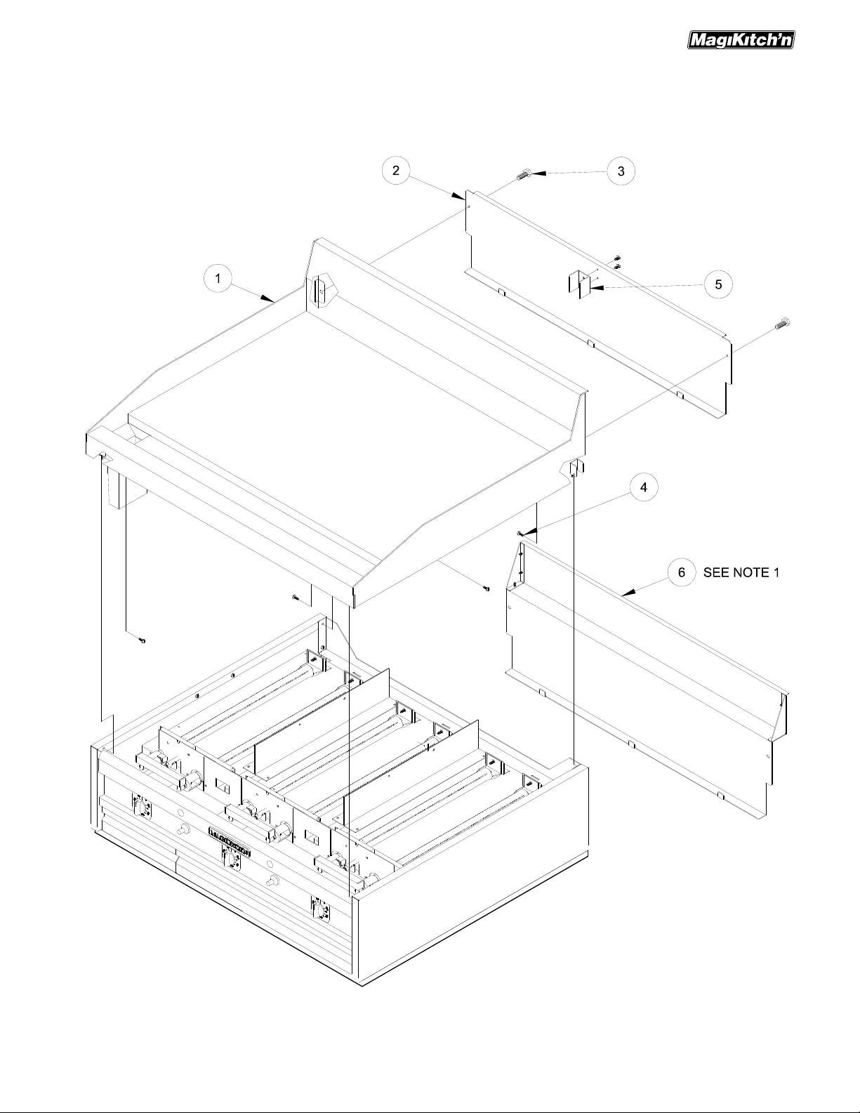
A) GRIDDLE ASSEMBLY
Griddle Assembly Exploded View A Parts List
ITEM # PART # PART DESCRIPTION
5125-1536701 Weld Assembly, MKG24 Plain Steel Griddle Top
5125-1536702 Weld Assembly, MKG36 Plain Steel Griddle Top
5125-1536703 Weld Assembly, MKG48 Plain Steel Griddle Top
5125-1536704 Weld Assembly, MKG60 Plain Steel Griddle Top
5125-1536705 Weld Assembly, MKG72 Plain Steel Griddle Top
5125-1536706 Weld Assembly, MKG24 Chrome Plated Griddle Top
5125-1536707 Weld Assembly, MKG36 Chrome Plated Griddle Top
5125-1536708 Weld Assembly, MKG48 Chrome Plated Griddle Top
5125-1536709 Weld Assembly, MKG60 Chrome Plated Griddle Top
5125-1536710 Weld Assembly, MKG72 Chrome Plated Griddle Top
5125-1516601 Weld Assembly, MKG24 Plain Steel Griddle Top, LH Trough
5125-1516602 Weld Assembly, MKG36 Plain Steel Griddle Top, LH Trough
5125-1516603 Weld Assembly, MKG48 Plain Steel Griddle Top, LH Trough
5125-1516604 Weld Assembly, MKG60 Plain Steel Griddle Top, LH Trough
1
5125-1516605 Weld Assembly, MKG72 Plain Steel Griddle Top, LH Trough
5125-1516606 Weld Assembly, MKG24 Chrome Plated Griddle Top, LH Trough
5125-1516607 Weld Assembly, MKG36 Chrome Plated Griddle Top, LH Trough
5125-1516608 Weld Assembly, MKG48 Chrome Plated Griddle Top, LH Trough
5125-1516609 Weld Assembly, MKG60 Chrome Plated Griddle Top, LH Trough
5125-1516610 Weld Assembly, MKG72 Chrome Plated Griddle Top, LH Trough
5125-1537101 Weld Assembly, MKG24 Plain Steel Griddle Top, RR Trough
5125-1537102 Weld Assembly, MKG36 Plain Steel Griddle Top, RR Trough
5125-1537103 Weld Assembly, MKG48 Plain Steel Griddle Top, RR Trough
5125-1537104 Weld Assembly, MKG60 Plain Steel Griddle Top, RR Trough
5125-1537105 Weld Assembly, MKG72 Plain Steel Griddle Top, RR Trough
5125-1537106 Weld Assembly, MKG24 Chrome Plated Griddle Top, RR Trough
5125-1537107 Weld Assembly, MKG36 Chrome Plated Griddle Top, RR Trough
5125-1537108 Weld Assembly, MKG48 Chrome Plated Griddle Top, RR Trough
5125-1537109 Weld Assembly, MKG60 Chrome Plated Griddle Top, RR Trough
5125-1537110 Weld Assembly, MKG72 Chrome Plated Griddle Top, RR Trough
5425-1531001 Cabinet Back, Removable MKG24
5425-1531002 Cabinet Back, Removable MKG36
2
5425-1531003 Cabinet Back, Removable MKG48
5425-1531004 Cabinet Back, Removable MKG60
5425-1531005 Cabinet Back, Removable MKG72
3 P0020600 Bolt, ¼-20 UNC x ½” Thread
4 P0075400 Screw, 10-24 x ½” Self Tap
5 5425-1540301 Cabinet, Back Spacer Bracket MKG
5425-1529701 Cabinet Back, Removable W/Flue MKG24
5425-1529702 Cabinet Back, Removable W/Flue MKG36
6
5425-1529703 Cabinet Back, Removable W/Flue MKG48
5425-1529704 Cabinet Back, Removable W/Flue MKG60
5425-1529705 Cabinet Back, Removable W/Flue MKG72
4
L22-288 Rev 0 (04/06)
Page 5
Exploded Parts-MKG Griddle Gas Models (All Options)
Griddle Assembly Exploded View A
NOTE 1: Item 2 can be replaced with item 6, this allows flue to vent upwards.
L22-288 Rev 0 (04/06)
5
Page 6

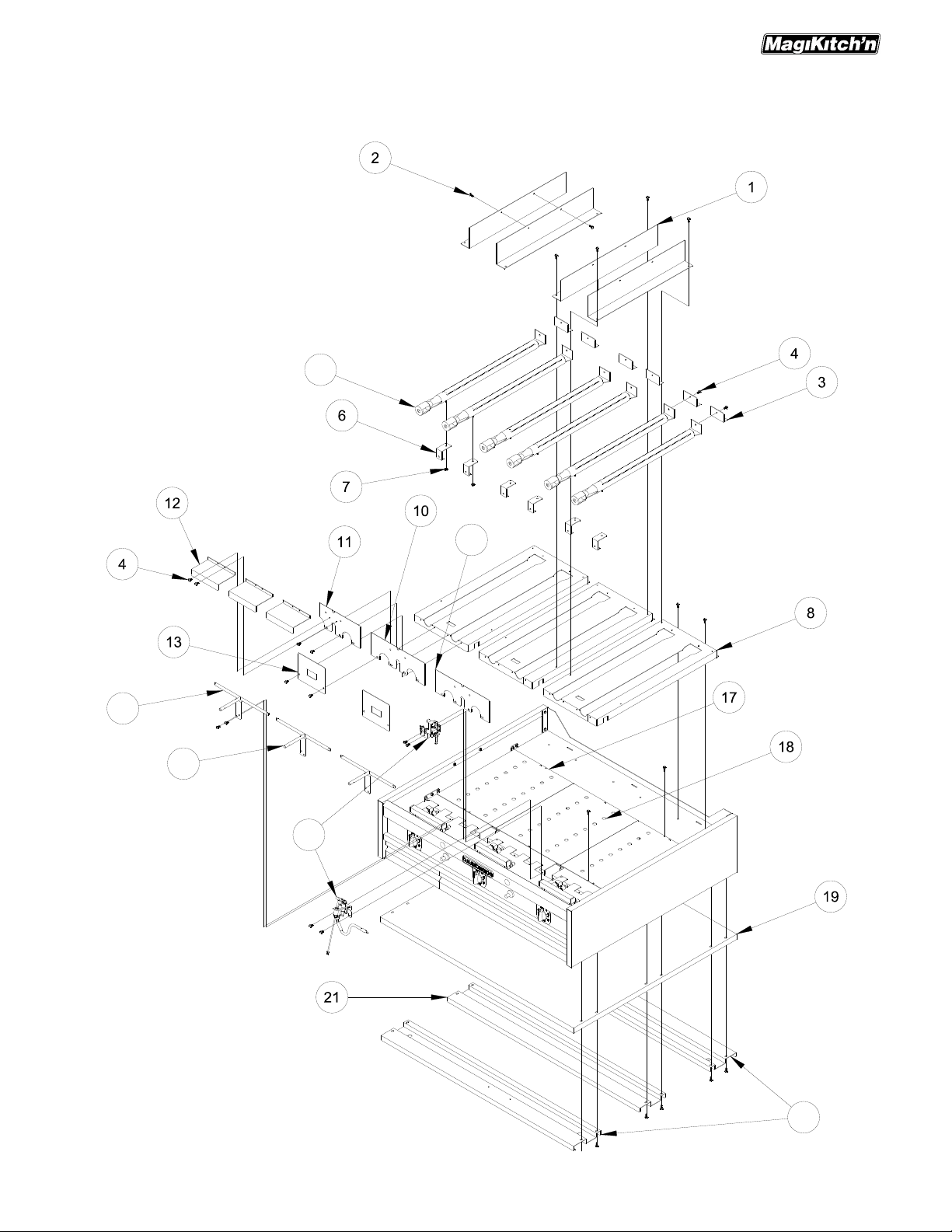
Exploded Parts-MKG Griddle Gas Models (All Options)
Griddle Assembly Exploded View A1 Parts List
ITEM # PART # PART DESCRIPTION
1
2
3
4
5
6
7
8
9
10
11
12
13
14
15
5425-1529301 Cabinet, Burner Upright Divider MKG
P0075400 Screw, 10-24 x ½” Self Tap
5425-1531301 Cabinet, Burner Mounting Bracket
P0076100 Screw, 10-24 x3/4” Self Tap
60138901 Burner, 1.25” Diameter
5425-1522301 Burner, Mounting Bracket front MKG
PP10196 Nut, 8-32 UNC
5425-1531201 Cabinet, Burner Mounting Plate MKG
5425-1531202 Cabinet, Burner Mounting Plate MKG LH Trough
5425-1530303 Cabinet, Burner Seal Plate MKG L/R Pilot
5425-1530302 Cabinet, Burner Seal Plate MKG Mid Pilot
5425-1530301 Cabinet, Burner Seal Plate MKG Mid
5425-1533201 Burner, Manifold Retainer Bracket MKG EI
5425-1529201 Pilot, Cover Plate MKG
5125-1509401 W/A, Runner Tube LH MKG
5125-1532801 W/A, Runner Tube LH with Side Chute MKG
5125-1509402 W/A, Runner Tube RH MKG
5225-1521801 C/A, Pilot Assy. MKG with Piezo Ignition
16
5225-1521802 C/A, Pilot Assy. MKG Nat with Matchless Ignition
5225-1521803 C/A, Pilot Assy. MKG LP with Matchless Ignition
17
18
5425-1530401 Cabinet, Shelf Seal Plate MKG Outer
5425-1530404 Cabinet, Shelf Seal Plate MKG Side Trough
5425-1530403 Cabinet, Shelf Seal Plate MKG Center
5425-1519101 Cabinet, Bottom Outer MKG24
5425-1519102 Cabinet, Bottom Outer MKG36
19
5425-1519103 Cabinet, Bottom Outer MKG48
5425-1519104 Cabinet, Bottom Outer MKG60
5425-1519105 Cabinet, Bottom Outer MKG72
5125-1519201 W/A, Cabinet Bottom Front and Rear MKG24
5125-1519202 W/A, Cabinet Bottom Front and Rear MKG36
20
5125-1519203 W/A, Cabinet Bottom Front and Rear MKG48
5125-1519204 W/A, Cabinet Bottom Front and Rear MKG60
5125-1519205 W/A, Cabinet Bottom Front and Rear MKG72
5425-1519001 Cabinet, Bottom Support MKG24
5425-1519002 Cabinet, Bottom Support MKG36
21
5425-1519003 Cabinet, Bottom Support MKG48
5425-1519004 Cabinet, Bottom Support MKG60
5425-1519005 Cabinet, Bottom Support MKG72
6
L22-288 Rev 0 (04/06)
Page 7
Exploded Parts-MKG Griddle Gas Models (All Options)
Griddle Assembly Exploded View A1
5
14
9
15
16
L22-288 Rev 0 (04/06)
20
7
Page 8

Exploded Parts-MKG Griddle Gas Models (All Options)
B) CONTROLS
Snap Action with Piezo Ignition Controls Exploded View B Parts List
ITEM # PART # PART DESCRIPTION
1
2
3
4
5
5425-1522802 Cabinet, Support Plate MKG Piezo
60119006 Tubing, Flexible .375” OD w.o Fitting 18”
60119007 Tubing, Flexible .375” OD w.o Fitting 30”
60119008 Tubing, Flexible .375” OD w.o Fitting 8”
60141301 Wrg, Ignition Angle X .093 Dia. Female
60138801 Themostat, Snap Action 200°-450°F
5425-1534601 Cabinet, Front Support Snap Action MKG24
5425-1534602 Cabinet, Front Support Snap Action MKG36
6
5425-1534603 Cabinet, Front Support Snap Action MKG48
5425-1534604 Cabinet, Front Support Snap Action MKG60
5425-1534605 Cabinet, Front Support Snap Action MKG72
7
8
9
10
5425-1508701 PG, Tstat Holder Bracket MKG
P0075400 Screw, 10-24 x ½” Self Tap
60092102 Nutsert, ¼-20 UNC THD
PP10687 Screw, 6-35 x 5/16” UNC Tr HD
5425-1540111 W/A, Front Panel Snap Action MKG24
5425-1540112 W/A, Front Panel Snap Action MKG36
11
5425-1540113 W/A, Front Panel Snap Action MKG48
5425-1540114 W/A, Front Panel Snap Action MKG60
5425-1540115 W/A, Front Panel Snap Action MKG72
12
13
14
A6087301 Label, Snap Action Thermostat
PP10944 Knob, Snap Action Thermostat
PP10023 Screw, 10-24 x3/8” Self Tap
5225-1534901 Door, Snap Action with Hinge MKG24
5225-1534902 Door, Snap Action with Hinge MKG36
15
5225-1534903 Door, Snap Action with Hinge MKG48
5225-1534904 Door, Snap Action with Hinge MKG60
5225-1534905 Door, Snap Action with Hinge MKG72
16
17
18
60141501 Ignitor, Piezo with Mounting Nut
P6071300 Magnet, Door
5125-1532401 W/A, Grease Box 3.7 Gal.
8
L22-288 Rev 0 (04/06)
Page 9

Exploded Parts-MKG Griddle Gas Models (All Options)
Snap Action with Piezo Ignition Controls Exploded View B
L22-288 Rev 0 (04/06)
9
Page 10

Exploded Parts-MKG Griddle Gas Models (All Options)
Matchless Ignition Controls Exploded View B1 Parts List
ITEM # PART # PART DESCRIPTION
5425-1530801 Heat Shield, Mid MKG24
5425-1530802 Heat Shield, Mid MKG36
1
5425-1530803 Heat Shield, Mid MKG48
5425-1530804 Heat Shield, Mid MKG60
5425-1530805 Heat Shield, Mid MKG72
2
P0075400 Screw, 10-24 x ½” Self Tap
5425-1540101 W/A, Front Panel Upper MKG24
5425-1540102 W/A, Front Panel Upper MKG36
3
5425-1540103 W/A, Front Panel Upper MKG48
5425-1540104 W/A, Front Panel Upper MKG60
5425-1540105 W/A, Front Panel Upper MKG72
4
5
6
7
601424101 Switch, Rocker DPDT 120V W/ Red Lamp
60142301 Lamp, Neon 120V Amber
5425-1529601 Bracket, Mounting Tstat Box MKG EI
60142801 Thermostat, 200-550°F Electric KX-458-36
60142501 Control, Temp 150-550°F Solid State
5425-1529701 Bracket, Thermostat Mounting Plate MKG24 EI
5425-1529702 Bracket, Thermostat Mounting Plate MKG36 EI
8
5425-1529703 Bracket, Thermostat Mounting Plate MKG48 EI
5425-1529704 Bracket, Thermostat Mounting Plate MKG60 EI
5425-1529705 Bracket, Thermostat Mounting Plate MKG72 EI
9
10
11
12
60129403 Knob, ¼” Collet SSTC Thermostat
PP10023 Screw, 10-24 x3/8” Self Tap
PP10693 Screw, 10-24 x 3/8” Trs Hd
PP10687 Screw, 6-32 x 5/16” Trs Hd
5125-1530701 W/A, Front Panel Lower MKG24 EI
5125-1530702 W/A, Front Panel Lower MKG36 EI
13
5125-1530703 W/A, Front Panel Lower MKG48 EI
5125-1530704 W/A, Front Panel Lower MKG60 EI
5125-1530705 W/A, Front Panel Lower MKG72 EI
14
15
16
17
18
19
20
21
22
23
24
25
5425-1508701 PG, Tstat Holder Bracket MKG
60092102 Nutset, ¼-20 UNC THD
60141101 Probe, RTD 1K DIN 13” MKG
5425-1523001 Probe, Retainer Bracket MKG EI
5125-1532401 W/A, Grease Box 3.7 Gal.
A6087302 Label, SSTC Thermostat
B6780901 Wrg, Dual Control Panel MKG EI, (Harness Not Shown)
B6781001 Wrg, Single Control Panel MKG EI, (Harness Not Shown)
B6781101 Wrg, Dual Valve MKG EI, (Harness Not Shown)
B6781201 Wrg, Single Valve MKG EI, (Harness Not Shown)
700342-1 Schematic, Label MKG EI W/ SSTC, (Not Shown)
700342-2 Schematic, Label MKG EI W/ ESTAT, (Not Shown)
10
L22-288 Rev 0 (04/06)
Page 11

Exploded Parts-MKG Griddle Gas Models (All Options)
Matchless Ignition Controls Exploded View B1
10
7
L22-288 Rev 0 (04/06)
11
Page 12

Exploded Parts-MKG Griddle Gas Models (All Options)
C) CABINET
Cabinet Frame Exploded View C Parts List
ITEM # PART # PART DESCRIPTION
1
2
5225-1532601 Cabinet, Left Hand Side MKG
5225-1532602 Cabinet, Right Hand Side MKG
5425-1530901 Cabinet, Back Support MKG24
5425-1530902 Cabinet, Back Support MKG36
5425-1530903 Cabinet, Back Support MKG48
5425-1530904 Cabinet, Back Support MKG60
3
5425-1530905 Cabinet, Back Support MKG72
5425-1530906 Cabinet, Back Support MKG24 Rear Trough
5425-1530907 Cabinet, Back Support MKG36 Rear Trough
5425-1530908 Cabinet, Back Support MKG48 Rear Trough
5425-1530909 Cabinet, Back Support MKG60 Rear Trough
5425-1530910 Cabinet, Back Support MKG72 Rear Trough
5425-1530501 Cabinet, Grease Box Enclosure MKG LH Matchless
5425-1530502 Cabinet, Grease Box Enclosure MKG RH Matchless
5425-1530503 Cabinet, Grease Box Enclosure MKG LH Side Chute Matchless
5425-1530504 Cabinet, Grease Box Enclosure MKG RH Side Chute Matchless
5425-1530505 Cabinet, Grease Box Enclosure MKG LH Rear Chute Matchless
4
5425-1530506 Cabinet, Grease Box Enclosure MKG RH Rear Chute Matchless
5425-1530507 Cabinet, Grease Box Enclosure MKG LH Snap Action
5425-1530508 Cabinet, Grease Box Enclosure MKG RH Snap Action
5425-1530509 Cabinet, Grease Box Enclosure MKG LH Side Chute Snap Action
5425-1530510 Cabinet, Grease Box Enclosure MKG RH Side Chute Snap Action
5425-1530511 Cabinet, Grease Box Enclosure MKG LH Rear Chute Snap Action
5425-1530512 Cabinet, Grease Box Enclosure MKG RH Rear Chute Snap Action
5
6
5425-1531401 Cabinet, Gas Supply Pipe Bracket MKG
5425-1520302 Cabinet, Inner Upright Support MKG
5425-1521901 Cabinet, Inner Front Support MKG24
5425-1521902 Cabinet, Inner Front Support MKG36
7
5425-1521903 Cabinet, Inner Front Support MKG48
5425-1521904 Cabinet, Inner Front Support MKG60
5425-1521905 Cabinet, Inner Front Support MKG72
8
P0075400 Screw, 10-24 x ½” Self Tap
5425-1539902 Grease Box, Enclosure Floor LH MKG Matchless
9
5425-1539904 Grease Box, Enclosure Floor RH MKG Matchless
5425-1539906 Grease Box, Enclosure Floor LH MKG Snap Action
5425-1539908 Grease Box, Enclosure Floor RH MKG Snap Action
12
L22-288 Rev 0 (04/06)
Page 13

Exploded Parts-MKG Griddle Gas Models (All Options)
Cabinet Frame Exploded View C
SEE NOTE 1
5
NOTE 1: See following tables and drawing for these assembly diagrams and part number information.
L22-288 Rev 0 (04/06)
13
Page 14

Exploded Parts-MKG Griddle Gas Models (All Options)
D) GAS CONTROL PIPING
Snap Action with Piezo Ignition Gas Assembly Exploded View D Parts List
ITEM # PART # PART DESCRIPTION
1
2
3
4
5
6
7
8
9
10
11
12
13
14
15
16
17
18
19
20
21
22
23
P6071767 Valve, Manual Shut Off, ½” NPT
P70366605 Coupling, ½” NPT Mild Steel
60148201 Nipple, ½” x 12” NPT Blk Iron
60127601 Fitting, Brass ½” MNPT x Fem Swivel
60139101 Valve, Gas Safety Single T-Couple
P7037090 Nipple, ½” Close NPT Blk Iron
A8033101 Piping, Tee ½” FNPT x 15/16” Flare
A8029105 Coupling, Gas Supply, SG MKG
P7037750 Elbow, ½” Street NPT
60139401 Fitting, Straight Compression 1/4” NPT x 3/8” Tube
P7036855 Tee, ½” NPT Blk Iron
PP11056 Bushing, Reducer Hex ½” NPT x ¼” NPT
PP11134 Fitting, Elbow Compression ¼” NPT x 3/8” Tube
60129902 Fitting, Adapter Male Flare 45 x ½” MNPT (MKG60 & 72 Only)
60128001 Tube, Flexible w/ Fittings 16”(MKG60 & 72 Only)
60129301 Screw, 10-24 x 5/8” Mach HH ZN w/ Loc Tite
2701-0028200 Regulator, Natural Gas 3.0”-5.0”
2701-0028300 Regulator, Propane Gas 5.0”-12.0”
5225-1520001 Manifold, Main Burner MKG
5225-1520002 Manifold, Main Burner MKG Left Hand Trough
2908-1318207 Orifice, Natural Gas 5/64”
2908-1318208 Orifice, Propane Gas 1.15 MM
5425-1537701 Piping, Gas Bracket Stiffener Retainer
5425-1537801 Piping, Gas Bracket Stiffener
P0075400 Screw, 10-24 x ½” Self Tap
5425-1531401 Bracket, Gas Supply Pipe Inlet
14
L22-288 Rev 0 (04/06)
Page 15

Exploded Parts-MKG Griddle Gas Models (All Options)
Snap Action with Piezo Ignition Gas Assembly Exploded View D
23
SEE NOTE 1
11
6
9
5
3
7
2
21
10
OR
MKG24
L22-288 Rev 0 (04/06)
15
Page 16

Exploded Parts-MKG Griddle Gas Models (All Options)
Matchless Ignition Gas Assembly Exploded View D1 Parts List
ITEM # PART # PART DESCRIPTION
1
2
3
4
5
6
7
8
9
10
11
12
13
14
15
16
17
18
19
20
21
22
23
24
25
26
27
28
29
30
60141901 Control, Ignition Spark/Sense 120V w/o Cover
60141902 Control, Ignition Spark/Sense 120V w/ Cover
P0091400 Nutsert, 6-32 UNC THD
P0075400 Screw, 10-24 x ½” Self Tap
5425-1523302 Bracket, Ignition Control Module L/R
5425-1529501 Bracket, Component MKG EI
60086401 Fitting, Brass Compression 3/8” TU x 3/8” NPT
PP10690 Screw, 6-32 x ½” UNC THD
5425-1523801 Bracket, Piping Solenoid
P7036727 Plug, 3/8” NPT Steel
60142001 Valve, Dual Port 120 VAC
P7037301 Nipple, 3/8” Close NPT Blk Iron Pipe
60142101 Valve, Single Port 120 VAC
P7037797 Elbow, Brass Compression 1/8” TU x1/4” NPT
P7037675 Elbow, 90° 3/8” Blk Iron Pipe
P7037313 Nipple, 3/8” x 6-1/2” NPT Blk Iron Pipe
P7036901 Union, 3/8” NPT Blk Iron Pipe
P7036854 Tee, 3/8” NPT Blk Iron Pipe
60122902 Fitting, Male Adapter Flare 45 x ½”
P7036860 Tee, 3/4” NPT Blk Iron Pipe
60127601 Fitting, Brass ½” MNPT x Fem Swivel
60128001 Tube, Flexible w/ Fittings 16”(MKG60 & 72 Only)
2701-0028200 Regulator, Natural Gas 3.0”-5.0”
2701-0028300 Regulator, Propane Gas 5.0”-12.0”
P7037350 Nipple, 3/4” Close NPT Blk Iron Pipe
PP11095 Valve, Manual Shut Off,3/4” NPT
P7037679 Elbow, 90° 3/4” Blk Iron Pipe
60129301 Screw, 10-24 x 5/8” Mach HH ZN w/ Loc Tite
5425-1531401 Bracket, Gas Supply Pipe Inlet
A8029105 Coupling, Gas Supply, SG MKG
5225-1520001 Manifold, Main Burner MKG
5225-1520002 Manifold, Main Burner MKG Left Hand Trough
2908-1318207 Orifice, Natural Gas 5/64”
2908-1318208 Orifice, Propane Gas 1.15 MM
16
L22-288 Rev 0 (04/06)
Page 17

Exploded Parts-MKG Griddle Gas Models (All Options)
Matchless Ignition Gas Assembly Exploded View D1
SEE NOTE 1
19
21
18
17
2
6
13
L22-288 Rev 0 (04/06)
17
Page 18

Exploded Parts-MKG Griddle Gas Models (All Options)
Pilot Assembly Exploded View D2 Parts List
ITEM # PART # PART DESCRIPTION
1
2
3
4
PP11296 Pilot, Center Ignitor w/ Rajah Terminal
5425-1521201 Pilot, Bracket MKG Piezo
60088001 Screw, 10-32 x1/4” HHD SST
P6071331 Orifice, EI Pilot Natural Gas
P6071332 Orifice, EI Pilot Propane Gas
5
6
7
60141301 Wire, Ignition Piezo MKG
P5047540 Thermocouple, T46 24
60128801 Pilot Reverse standing SG Natural Gas
60128802 Pilot Reverse standing SG Propane Gas
8
9
10
11
5425-1526101 Pilot, Bracket MKG Matchless
A8036404 Electrode, Ignition/Flame Sense MKG EI
A8037001 Piping, Bracket Electrode Alignment
PP10023 Screw, 10-24 x3/8” Self Tap
18
L22-288 Rev 0 (04/06)
Page 19

Exploded Parts-MKG Griddle Gas Models (All Options)
Pilot Assembly Exploded View D2
4
3
L22-288 Rev 0 (04/06)
19
Page 20

E) ELECTRICAL INFORMATION
Solid State Control Schematic View E
115V, 50-60Hz
4A
BRN
BLK
Exploded Parts-MKG Griddle Gas Models (All Options)
PP10439
NEMA 5-15P
L N G
FRAME
WHT
BRN
BRN
LEFT
ON/OFF
S1A
1
S2A
1
RIGHT
ON/OFF
GRN/Y
WHT
MV1 LEFT
MAIN VALVE
WHT
PV1
PILOT VALVE
TYPICAL LAST BURNER
WHT
MV1
J/P1-2
3
RED
J/P1-4
L2
V2
L2
YEL
PV1
BGND
HV
LEFT
ON/OFF
LT1
120(9)
COM (8)
240(10)
NO (7)
HEAT
COM (6)
5
TC1
TEMP
CONTROL
1 3CW2
SET POINT
2
2
BLU
TP1
4
A
PILOT OK
GRY
ORG
J/P1-1
J/P1-3
R
4
S1B
ORG
L1
K3
K1
IM1
IGNITION
MODULE
5
TYPICAL TWO BURNER SET
RIGHT
120(9)
COM (8)
240(10)
HEAT
TC2
TEMP
CONTROL
1 3 2
NO (7)
COM (6)
ON/OFF
ORG
VIOL
5
TP2
4
WHT
5
W/RED
4
R
S2B
3
J/P1-5
MV1 RIGHT
MAIN VALVE
20
NEXT BRN
SET POINT
CW
NEXT WHT
L22-288 Rev 0 (04/06)
Page 21

Exploded Parts-MKG Griddle Gas Models (All Options)
Electric Thermostat Schematic View E1
PP10439
115V, 50-60Hz
NEMA 5-15P
L N G
4A
BRN
BLK
FRAME
WHT
BRN
BRN
LEFT
ON/OFF
S1A
1
S2A
1
RIGHT
ON/OFF
GRN/Y
WHT
MV1 LEFT
MAIN VALVE
WHT
PV1
PILOT VALVE
TYPICAL LAST BURNER
WHT
3
MV1
RED
PV1
BGND
HV
J/P1-2
J/P1-4
L2
V2
L2
YEL
LEFT
ON/OFF
LT1
A
PILOT OK
GRY
HEAT
TC1
TEMP
CONTROL
2
2
BLU
ORG
J/P1-1
J/P1-3
R
4
S1B
ORG
L1
K3
K1
IM1
IGNITION
MODULE
5
TYPICAL TWO BURNER SET
RIGHT
HEAT
TC2
TEMP
CONTROL
VIOL
ORG
WHT
ON/OFF
4
R
3
5
S2B
W/RED
J/P1-5
MV1 RIGHT
MAIN VALVE
NEXT BRN
L22-288 Rev 0 (04/06)
NEXT WHT
21
Page 22

Exploded Parts-MKG Griddle Gas Models (All Options)
Degrees
Degrees
Resistance
Solid State Control Temperature Probe Resistance Chart
Celsius (°C)
10 50 1039
20 68 1078
30 86 1117
40 104 1155
50 122 1194
60 140 1232
70 158 1271
80 176 1309
90 194 1347
100 212 1385
110 230 1423
120 248 1461
130 266 1498
Fahrenheit (°F)
In (Ohms)
0 32 1000
140 284 1536
150 302 1573
160 320 1610
170 338 1648
180 356 1685
190 374 1722
200 392 1758
210 410 1795
220 428 1832
230 446 1868
240 464 1905
250 482 1941
22
L22-288 Rev 0 (04/06)
Page 23

Exploded Parts-MKG Griddle Gas Models (All Options)
NOTES PAGE
L22-288 Rev 0 (04/06)
23
Page 24

www.magikitchn.com
In the event of problems with or questions
about your order, please contact the
MagiKitch’n factory at :
(800)258-3708 US and Canada only
(603)225-6684 World Wide
MAILING ADDRESS – P.O. BOX 501, CONCORD, NH 03302-0501
SHIPPING ADDRESS – 10 FERRY ST., CONCORD, NH 03301
L22-288 Rev 0 (04/06)
In the event of problems with or questions
about your equipment, please contact the
MagiKitch’n Authorized Service and Parts
representative (ASAP) covering your area,
or contact MagiKitch’n at the numbers
listed to the left.
 Loading...