

Page 1
600 CE SERIES
GAS BROILER
INSTALLATION – OPERATION - MAINTENANCE
MAGIKITCH’N
BOX 501
P.O.
CONCORD NH 03302-0501
TEL:603-225-6684
FAX 603-225-8497
WWW.MAGIKITCHN.com
L25-004 R3 (2/15)
1
Page 2

TO THE PURCHASER, OWNER AND STORE MANAGER
Please review these warnings prior to posting them in a prominent location for reference.
TO THE PURCHASER
Post in a prominent location the instructions to be followed in
the event that an operator smells gas. Obtain this
information from your local gas supplier.
FOR YOUR PROTECTION
DO NOT store or use gasoline or other flammable vapors
and liquids in the vicinity of this or any other appliance. Do
not spray aerosols in the vicinity of this appliance when it is
in operation.
WARNING
Improper installation, adjustment, operation, alteration,
service or maintenance can cause property damage, injury
or death. Read the installation, operating and maintenance
instructions thoroughly before installing, operation, servicing
this appliance.
WARNING
Installation, maintenance and repairs should be performed
by a Pitco Authorized Service and Parts (ASAP) company
technician or other qualified personnel. Installation,
maintenance or repairs by an unauthorized and unqualified
personnel will void the warranty.
WARNING
Installation and all connections must be made according to
local codes in force. In the absence of local codes in North
America, the installation must conform with the National
Fuel Gas Code, ANSI Z223.1/NFPA 54 or the Natural Gas
and Propane Installation Code CSA B149.1 as applicable.
In Australia, the appliance must installed in compliance
with AS/NZS 5601.
WARNING
During the warranty period if a customer elects to use a nonoriginal part or modifies an original part purchased from
Pitco and/or its Authorized Service and Parts (ASAP)
companies, this warranty will be void. In addition, Pitco and
its affiliates will not be liable for any claims, damages or
expenses incurred by the customer which arises directly or
indirectly, in whole or in part, due to the installation of any
modified part and/or received from an unauthorized service
center.
WARNING
Adequate means must be provided to LIMIT the movement
or this appliance without depending on the gas or electrical
cord connection. Single appliances equipped with legs must
be stabilized by installing anchor straps. All appliances
equipped with casters must be stabilized by installing
restraining chains.
WARNING
An appliance equipped with casters and a flexible gas line
must be connected to the gas supply with a quick disconnect
device. In North America this quick disconnect must comply
with ANSI Z24.41. In Australia, the quick disconnect must
comply with AS 4627.
WARNING
DO NOT alter or remove structural material on the appliance
to accommodate placement under a ventilation hood.
WARNING
The appliance is NOT jet stream approved. DO NOT clean
the appliance with a water jet.
WARNING
DO NOT use an open flame to check for gas leaks!
L25-004 R3 (2/15)
DO NOT sit or stand on this appliance. The appliance’s front
panel, tank, splash back, tank cover, workshelf, drain board
is not a step. Serious injury could result from slipping, falling
or contact with hot surface.
NEVER use the appliance as a step for cleaning or
accessing the ventilation hood. Serious injury could result
from slips, trips or from contacting hot surface.
This appliance is intended for indoor use only.
DO NOT operate appliance unless all panels and access
covers are attached correctly.
It is recommended that this appliance be inspected by a
qualified service technician for proper performance and
operation on a yearly basis.
There is an open flame inside this appliance. The unit may
get hot enough to set nearby materials on fire. Keep the area
around the appliance free from combustibles.
DO NOT supply the appliance with a gas that is not indicated
on the data plate. If you need to convert the appliance to
another type of fuel, contact your dealer.
If gas flow to appliance is interrupted, or pilots extinguish,
wait 5 minutes before attempting to relight the pilot to allow
any residual gas in appliance to dissipate.
Ensure that the appliance can get enough air to keep the
flame burning correctly. If the flame is starved for air, it can
give off a dangerous carbon monoxide gas. Carbon
monoxide is a clear odorless gas that can cause suffocation.
This appliance is intended for professional use only and
should be operated by fully trained and qualified personnel.
In North America, gas appliances equipped with casters
must be installed with connectors that comply with the
Standard for Connectors for Movable Gas Appliances,
ANSI Z21.69.CSA 6.16 Latest Edition. This connection
should include a quick disconnect device that complies
with the Standard for Quick Disconnect Devices for Use
With Gas Fuel ANSI Z21.41.CSA 6.9 Latest Edition. In
Australia, an appliance equipped with casters and a
flexible gas line must be connected to the gas supply with
a quick disconnect device that complies with AS 4627 and
a restraining cable. The restraining cable must not exceed
80% of the length of the flexible gas line.
This appliance is not intended for use by person (including
children) with reduced physical, sensory or mental
capabilities, or lack of experience and knowledge, unless
they have been given supervision or instruction concerning
use of the appliance by a person responsible for their safety.
Children should be supervised to ensure that they do not
play with the appliance.
2
WARNING
WARNING
WARNING
WARNING
WARNING
WARNING
WARNING
WARNING
WARNING
WARNING
WARNING
Warning
Page 3

TableofContents
Installation
Delivery and Location
Broiler Assembly
Gas Conversion
Gas Connection
Operation
Gas Connection and Conversion Information for 600-CE Model Broilers
Broiler Set Up
Lighting Instructions
General Charbroiling Tips
Maintenance
Cleaning and Preventative Maintenance
Accessory and Replacement Parts List
SMB ................................................................................................................................................................................................. 15
600 SERI ES-C E ............................................................................................................................................................................... 15
1. Lighting Instructions
2. Initial Set-Up
3
.
4
.
ORIGINAL EQUIPMENT WARRANTY ....................................................................................................................................... 19
.......................................................................................................................................................................................... 4
................................................................................................................................................................... 4
........................................................................................................................................................................... 5
............................................................................................................................................................................... 6
............................................................................................................................................................................... 6
............................................................................................................................................................................. 7
................................................................................ 7
................................................................................................................................................................................ 8
..................................................................................................................................................................... 9
........................................................................................................................................................... 10
......................................................................................................................................................................... 12
.................................................................................................................................... 12
....................................................................................................................................... 13
............................................................................................................................................................ 15
......................................................................................................................................................................... 16
Typical SMB 600 Series Illustration
Accessory / Parts List For SMB 600 Series Models
(Model SMB 636 shown) .................................................................................. 17
..................................................................................................... 18
L25-004 R3 (2/15)
3
Page 4

b
t
N
Delivery and Location
DELIVERY
Each broiler was carefully inspected and packaged
being tendered to the carrier. Upon delivery of your new
broiler:
• Uncrate the broiler and check for damage. Mos
carriers will accept claims for damage if they are
notified within seven days of delivery and the sh ipp ing
container is retained for inspection.
OTE: The broiler top grid is shipped underneath the
unit.
packing crate.
MagiKitch’n cannot assume responsibility fo r loss or
damage suffered in transit. The carrier assumed full
responsibility for delivery in good order when the
shipment was accepted.
For installation or maintenance, contact your local dealer or authorized service
by other than MagiKitch’n authorized service agencies or personnel may void warranty coverage.
Call Pitco Frialator Technical Support at 603-225-6684 who will put you in touch with the proper local service
organization or make service arrangements for you.
Installation
efore
Be sure to remove it before disposing of the
LOCATION
• Place the unit in a properly ventilated area.
• Keep the area free and clear of all combustibles such
as paper, cardboard, and flammable liquids
solvents.
• This unit requires 0cm minimum clearance to non–
combustible construction. The unit is not approved for
installation in areas with combustible construction.
• Provisions must be made for an adequate air supply to
the broiler.
the
• Keep
obstructions that could block the flow of combustion
and ventilation air.
• Be sure there is sufficient clearance at the rear of the
unit for gas connections, regulator and any master
shutoff valve(s) to be installed.
• The location must provide adequate clearance for
servicing.
Before making any gas connections to this broiler, check
that the available gas supply meets the requirements for
supply pressure and gas type shown on the rating plate on
the front of the unit.
area in
front
of the unit free
agent
. Installation or service
from
and
4
L25-004 R3 (2/15)
Page 5
r
d
Installation
Broiler Assembly
NOTE: This appliance shall be installed in accordance
with current regulations and used only in a well–
.
ventilated space
installing and using this appliance.
NOTE: Installation and connection must be performed by
a qualified installer only.
COUNTERTOP MODELS
Countertop models must be sealed to the counter surface in
compliance with National and Local Sanitation standards.
1
. Apply a 13mm bead of silicone to the bottom of the
broiler. The silicone should run approximately 6mm
from the front, back and side edges of the unit.
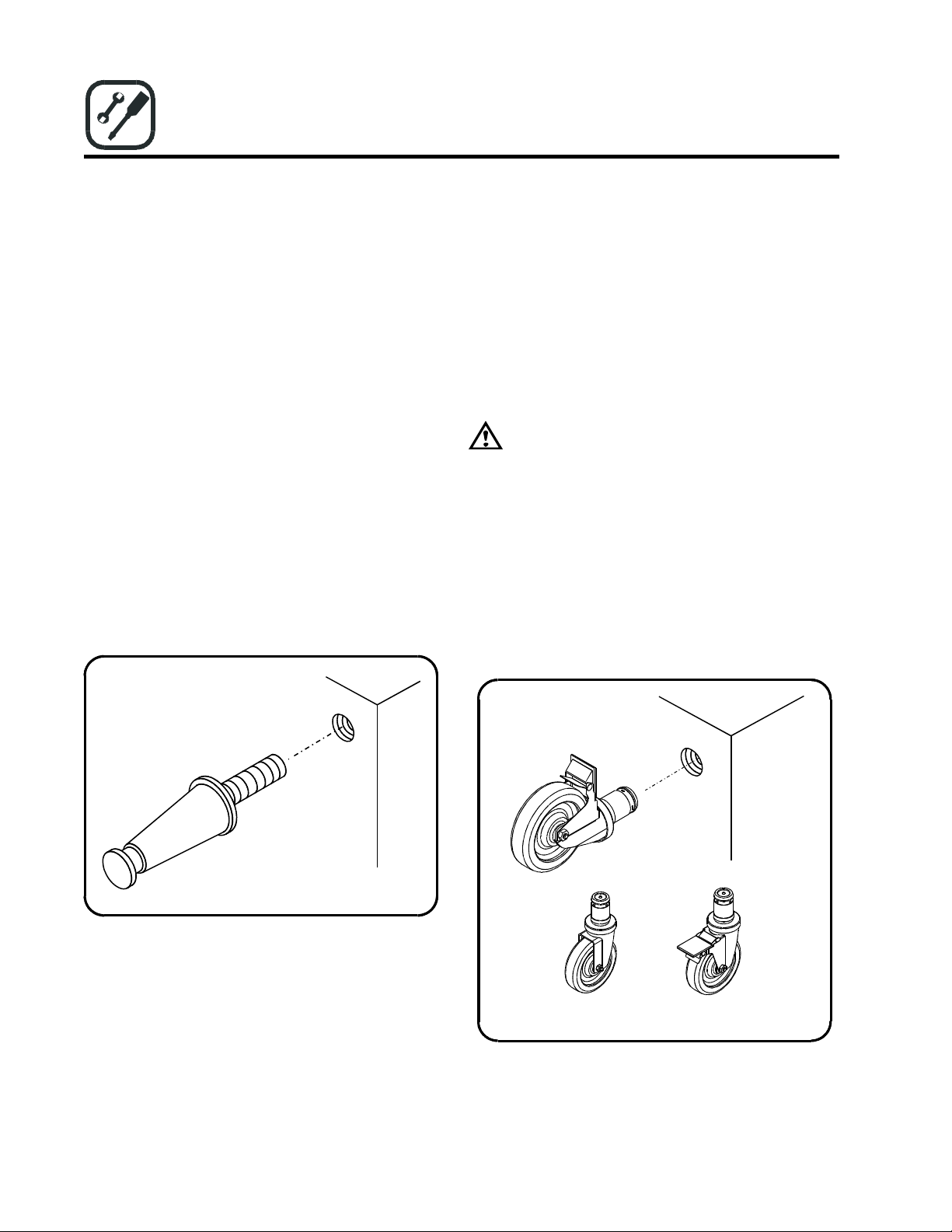
LEG ATTACHMENT
The 15 cm legs are packed in the top section of the broiler.
1
. Screw the legs into the threaded holes in the corners
on the bottom of the broiler.
2
. Place the broiler onto the legs.
3
. Turn the adjustable leg feet to level the oven.
Refer to these instructions before
Figure 1
CASTER INSTALLATION
A flexible hose/connector must be used on any broile
installed on casters. The connector must meet National an
Local codes.
A restraint must be used to limit the movement of the
appliance. Limited movement cannot depend on the
flexible connector. DO NOT attach the restraint to gas
piping or electrical conduit!
WARNING!!
If the restraint is disconnected for any reason it
must be reconnected when the unit is returned to
its original position.
1. Screw the casters into the threaded ho les in the corners
on the bottom of the broiler.
NOTE: The locking casters must be installed on the
front of the broiler.
2. Place the broiler onto the casters.
Figure 2
5
L25-004 R3 (2/15)
Non-locking
Caster
Locking
Caster
Page 6

d
t
t
r
a
t
r
N
r
N
s
d
h
w
t
a
r
Gas Connection
An adequate gas supply is required for proper broiler
performance. With all burners on “HIGH”, the manifold
pressure should not show any appreciable drop.
Fluctuations of more than 25% will create pilot problems
and affect burner operation.
WARNING!!
This unit must be connected ONLY to the type
of gas specified on the rating plate.
1. Remove the hairpin clips securing the burners. This
will allow for removal of the burners for inspection,
cleaning and servicing.
2. Attach the regulator supplied with the unit. The
regulator must be installed at the entry end of th e gas
manifold.
NOTE: Be sure the regu lator is installed so that the
gas flows in the same direction as the
arrow on the bottom of the regu lator.
the supplied regulator only. Use of any
will
other regulator
warranty.
3. Adju st the regulator to the burner pressure listed on
the rating plate. Refer to the table on the follo wing
page for proper pressure settings.
NOTE: A pressure regulator is not required for all
countries.
4. Use pipe joint compound suitable for use with LP
gas on all threaded connections.
5. Turn off all burner valves.
6. Turn on the gas supply. Check all connections for
gas leaks using soap and water. Never use an open
flame to check for gas leaks!
invalidate
Use
the
Installation
Gas Conversion
All units are shipped with the appropriate orifices an
components required for the gas requested. If the uni
does not perform well or has unsatisfactory flame
characteristics (too high, yellow tips, lifting), check tha
the supply pressure and orifice size are appropriate fo
the gas used before making any adjustments.
Use the following directions to convert the unit to
different type of gas if necessary. Each conversion ki
contains all the orifice sizes and markings required fo
converting any size unit to any gas type in all countries.
ote that in Belgium units may not be converted.
some conversions it may also be necessary to replace the
regulator or restrictor orifice.
OTE: Refer to the table on the following page to
determine gas requirements, pressure
and orifice sizes.
1.
Shut off the gas supply to the unit.
Disconnect the unit from the gas supply.
2.
3.
Remove the top grids, radiants, runner tubes an
burners.
Remove the brass runner tube orifice. Replace wit
4.
the new orifice.
Remove all burner orifices. Replace with the ne
5.
orifices.
Adjust the air shutters on all the burners to the
6.
correct opening. Mark the air shutter at the correc
setting. Re-install the burners.
Re-install the runner tubes, radiants, and top grids.
7.
8.
Adjust the regulator to the correct gas pressure. If
restrictor orifice is required in place of the regulato
to meet your countries specific codes, remove the
old restrictor orifice and replace it with a new one
correctly
specified for the gas type being used.
Adhere the appropriate conversion sticker to the
front of the unit, near the rating plate.
sized to provide the burner pressure
Fo
ettings
6
L25-004 R3 (2/15)
Page 7

Operation
Gas Connection and Conversion Information for 600-CE Model Broilers
Appliance Gas
Country Category Category Type
NL
II2L3B/P
II2L3P
BE
I2E+
I3+
FR
II2E+3+
DE
II2ELL3B/P 2ELL G20/25
GB
II2H3P
IT
ES
PT
SE
DK
FI
AT
NO
IE
GR
LU
II2H3+
II2H3+
II2H3+
II2H3B/P
II2H3B/P
II2H3B/P
II2H3B/P
I3B/P
II2H3P
II2H3B/P
II2E3B/P
Gas
2L G25
3B/P G30
3P G31
2E+ G20/25
3+ G30/31
2E+ G20/25
3+ G30/31
3B/P G30
2H G20
3P G31
2H G20
3+ G30/31 30-37
2H G20
3+ G30/31
2H G20
3+ G30/31
2H G20
3B/P G30
2H G20
3B/P G30
2H G20
3B/P G30
2H G20
3B/P G30
3B/P G30
2H G20
3P G31
2H G20
3B/P G30
2E G20
3B/P G30
Supply Burner
Pressure Pressure Burner Shutter
(mb)
25
30
50
20/25
30-37
20/25
30-37
20
50
20
50
20
20
30-37
20
30-37
20
30
20
30
20
30
20
50
30
20
50
20
50
20
50
10.7
29.5
36.5
16.6/20.6 1.5
29.5-36.5 1.02
16.6/20.6 1.5
29.5-36.5 1.02
16.6-10.7 1.5-1.85 9.O-open
29.5
16.6
36.5
16.6
29.5-36.5 1.02
16.6
29.5-36.5
16.6
29.5-36.5 1.02
16.6
29.5
16.6
29.5
16.6
29.5
16.6
29.5
29.5
16.6
36.5
16.6
29.5
16.6
29.5
(mb)
Main
(mm)
1.85
1.02
1.02
1.02
1.5
1.02
1.5
1.5
1.02
1.5
1.5
1.02
1.5
1.02
1.5
1.02
1.5
1.02
1.02
1.5
1.02
1.5
1.02
1.5
1.02
Air
(mm)
open
open
open
9.0
open
9.0
open
open
9.0
open
9.0
open
9.0
open
9.0
open
9.0
open
9.0
open
9.0
open
9.0
open
open
9.0
open
9.0
open
9.0
open
Runner Tube Orifice (mm)
Gas
Type
G20
G25
G30
G31
Heat Input (kW)
Hs
Hi
L25-004 R3 (2/15)
624/648 630/660 636/672
624
16.5
14.9
0.87
0.87
0.52
0.52
0.98
1.065
0.98
1.065
0.58
0.63
0.58
0.63
630
25.2
22.7
636
29.3
26.4
648
660
41.1
50.1
37.1
45.2
7
Page 8

a
d
¾
t
Operation
Broiler Set Up
NOTE: After
Top Cooking Grid
The cooking grid has two positions, flat or tilted.
• To place the grid in the tilted position, push down on
the grid handle and pull forward to engage the grid
hook.
• To place the grid in the flat position, pull up on the
grid handle and push back to disengage the grid hook.
When broiling, the grid must be in the tilted position.
This allows some of the grease to drain into the front
trough, reducing both smoke and flare–up. The flat
position should only be used to heat soups, sauces, etc.
DO NOT use the flat position for broiling.
initial
installation, the unit must be
thoroughly cleaned prior to operation. Refer to
the Maintenance section of this manual for
cleaning instructions.
Radiant
Top Grid
Right Water Tub
Left Water T ub
Figure 3
Radiants and Grease Shield
The radiants must be in place prior to operating the unit.
The radiants provide protection for the burners, create
surface for the flare–up required for charbroiling an
provide radiant heat to the product.
Water Tubs
The tubs are designed to reduce flare–up and eliminate
flash back. Any flaming grease that drips down is
extinguished when it hits the water. The tubs should be
full of water. NEVER allow the water tubs to run dry.
Grease Box
The majority of the grease will travel down the fron
trough and into the grease box. The grease bo x must be
in place while operating the unit
.
Grid Hook
Top Cooking Grid
Tilt Block
Side View of Top Grid
In tilt p osit ion
Grease Box
8
L25-004 R3 (2/15)
Page 9

fter
f
Operation
1
. Turn all burners to OFF.
2
. Remove the top grid.
3
. Remove the last radiant on the right.
4
. Turn the shut off valve to ON.
5
. Press and hold the reset (blue) button on the safety
pilot valve. Wait 15–30 seconds. Light the runner
tube
. DO NOT release the reset button.
NOTE: If the runner tube does not ligh t, wait a few
seconds, then try again.
NOTE: When lighting the runner tub e for the first
time after connecting the unit to the gas
source, the light time will probably increase
to 1–2 minutes.
Top Grid
Radiant
Safety Pilot Valve
(located under
shelf)
Thermocouple
(located on far
end of runner tube)
Lighting Instructions
6. Wait an additional 15–30 seconds. Release the reset
button. The runner tube should remain lit.
NOTE: If the runner tube fails to ignite, repeat step
5. If the runner tube fails to ignite a
three attempts,
MagiKitch’n service agent.
7
. Replace the radiant and top grid.
8. Push and turn the burner valves to operate the
individual burners as needed.
Broiler Shut Down
1. Turn the shut off valve to OFF.
2. Turn all burners to OFF.
Off
On
Shut-of
Valve
Reset Button
Safety Pilot Valve
contact
an authorized
Figure 4
9
L25-004 R3 (2/15)
Page 10

–
t
peak
t
r
d
Operation
General Charbroiling Tips
PREHEATING
The broiler must be preheated before cooking. We
recommend a preheat time of 10-15 minutes. After
preheating, the broiler will be hot enough to cook on
without sticking and will produce the proper searing
effect.
COOK ZONES
There are three separate cooking zones
MagiKitch’n charbroiler:
• The front 1/3 of the broiler is the coolest section.
• The center 1/3 of the broiler has medium heat.
• The rear 1/3 of the broiler is th e hottest. (even though
it is the farthest from the burner in the tilt position)
The three cook zones enable more efficient cooking
without flame adjustment. It is possible to cook a rare,
medium and well done steak in the same amount of time
simply by placing the product in different cook zones.
The cooking process can also be slowed or increased by
moving product between zones.
on your
FLARE–UP
In charbroiling, a certain amount of flare–up is desirable
in order to flavor the product. However, excess flare–up
burns product and leaves a bitter taste. Generally, flare
up increases with the heat of the broiler and the fa
content of the product.
Heat Product Fat Content
High
Low
The cook zones can be used to advantage during
periods. High fat product can be cooked in the cool fron
section, while lean product is placed on the hotter rea
section. This allows for better control of flare–up an
product quality.
High
High Flare–up
Moderate Low Flare–up
Low
Moderate
10
L25-004 R3 (2/15)
Page 11

d
h
d
N
N
F
Operation
MARKING PRODUCT
1
. Place the product diagonally on the back 1/3 of a
clean broiler grid.
NOTE: For white fleshed product (chicken, fish) be
sure Marking product to baste the product
and brush the grid with pure vegetable oi l .
2
. When the product is marked, rotate it ¼ turn to
provide the diamond pattern.
NOTE: This step can be eliminated if only one lin e
is desired.
Rear of Broiler
ront of Broiler
Step 1
Rear of Broiler
Hot
Medium
Cool
Front of Broiler
3. When the diamond mark is achieved, turn the foo
over and move to the middle cook zone to finis
broiling. DO NOT turn the food over to the marke
side or the pattern will be marred.
OTE: For thicker and well done products, move
the product to the front cook zone.
OTE: Check the internal product temperature on
the unmarked side.
4.
Serve the food with the pattern facing up.
Rear of Broiler
Hot
Medium
Cool
Front of Broiler
Step 2
Step 3
Figure 5
11
L25-004 R3 (2/15)
Page 12

r
N
Maintenance
Cleaning and Preventative Maintenance
Proper maintenance of your broiler will prolong the life
of the appliance and ensure proper performance.
DAILY CLEANING
Top Grid
1
. Remove the grid.
2
. Use the MagiKitch’n scraper to remove any cooking
debris from the rods, especially the underside.
3
. Clean the frame including the tubes and angles on
the sides, front and back with steel wool.
Cabinet, Shelves, Water Tubs, and Grease Boxes
These parts are stainless steel and can be cleaned with
any non–toxic industrial stainless steel cleaner.
1
. Apply cleaners when the broiler is cold. Always rub
with the grain of the metal.
Water Tubs
Empty the excess grease and water. Wipe the tubs clean.
Grease Box
The grease box should be emptied daily.
ANNUAL MAINTENANCE AND INSPECTION
Disconnect all gas sources before you perform
this procedure. .The unit should be in spected
annually by a qualified gas appliance service personnel.
The main burner valves should be greased annually, or as
necessary, to maintain smooth operation and prevent gas
leakage.
1. Remove the knobs from the front of the unit.
2. Remove the outer front panel.
3. Loosen the two screws securing the collar to each
valve.
4. Carefully disassembly the valves. See Figure 6.
5
. Clean all parts.
6. Apply high temperature valve grease to the roto
assembly.
OTE: The valve grease must be suitable for all
gas types.
7.
Reassemble the valves and broiler.
WEEKLY CLEANING
Soak the top grid in a degreasing solution. The grid will
need to be re–seasoned after soaking.
Orifice Body Rotor Spring Stem Collar
Figure 6
12
L25-004 R3 (2/15)
Page 13

Maintenance
Accessory and Replacement Parts List
NOTE: This is a partial parts list for parts not shown here, call MagiKitch’n or a MagiKitch’n service representative.
Always give the Model and Serial Numbers of your unit when ordering parts and accessories.
Item Description
Top grid
1
Radiant
2
Burner
3
Burner clip
4
Baffle, right side
5
Baffle, left side
6
Outer side
7
Inner side (right)
8
Inner side (left)
9
Drip cup
10
Outer back
11
Inner back
12
Rear support angle
13
Rear burner support
14
Water tub
15
Grease trough
16
Towel bar
17
Lower shelf
18
Upper shelf
19
Base assembly
20
Upper shelf
21
Inlet manifold
22
Runner tube
23
Inner front assembly
24
90
°
25
elbow with clip
Item
26
27
28
29
30
31
32
33
34
35
36
37
38
39
40
41
42
43
44
45
46
47
48
49
Description
Valve (push to turn)
Pressure tap orifice
Heat shield
Manifold, weld assembly
Outer front
Knob
Grease trough
Service shelf
Service shelf support
Thermocouple (not shown)
Thermocouple bracket (not shown)
½” NPT Jam nut
½” FNPT Shut off valve
½” NPT nipple
¾” MNPT x ½” FNPT adaptor
180° return elbow
¾” close nipple
Safety pilot valve
Runner supply tube
L25-004 R3 (2/15)
13
Page 14

Maintenance
Figure 7
L25-004 R3 (2/15)
14
Page 15

SMB
600 SERI ES-C E
1
.
Lighting Instructions
SMB 600 Series -CE Models with safety pilot
1. Turn all burners to OFF.
.
Remove the top grid.
2
.
Turn the shut off valve to ON.
3
4. Press and hold the reset (blue) button on the safety pilot valve. Wait 15–30 seconds. Light the runner tube.
DO NOT release the reset button.
NOTE: If the runner tube does not light, wait a few seconds , then try again.
NOTE: When lighting the runner tube for the first time after connecting the unit to the gas source, the light time
will probably increase to 1–2 minutes.
5
.
Wait an additional 15–30 seconds. Release the reset button. The runner tube should remain lit.
NOTE: If the runner tube fails to ignite, repeat step 5
contact an authorized MagiKitch’n service agent.
.
Replace the top grid.
5
.
Push and turn the burner valves to operate the individual burners as needed .
6
Broiler Shut Down
1. Turn the shut off valve to OFF.
2
.
Turn all burners to OFF.
L25-004 R3 (2/15)
. If the runner tube fails to ignite after three attempts,
15
Page 16

SMB 600 Series -CE Models with safety pilot
2. Initial Set-Up
SMB 600 Series-CE models
COAL SUPPORT - The coal support must be installed so that it is pushed against the back wall
of the unit
COALS - Use only Magicoals supplied by MagiKitch’n. Do not use lava rock or other replacement
coals.
application
This will cause excessive flare up, reduce ventilation, and cause overheating of the valves and
other components.
. This creates an air gap over the runner tube to allow proper ventilation.
They do not perform as well or last as long as the Magicoals that were designed for this
. Place the coals evenly across the surface of the coal support. Do not pile them up.
PREHEATING - It is necessary to preheat a cold broiler each time before cooking. The recommended time is 15-20 minutes for
coal style charbroilers, at which time the cooking grid should be hot enough to cook on without sticking, and will produce the
proper searing effect.
16
L25-004 R3 (2/15)
Page 17

3
.
Typical SMB 600 Series Illustration
Note: Your unit may vary from this typical diagram.
(Model SMB 636 shown)
L25-004 R3 (2/15)
17
Page 18

4
.
Accessory / Parts List For SMB 600 Series Models
Not all parts are illustrated, nor are all parts are listed. If you need a part that is not listed here, call MagiKitch’n for a quote. Always
have your model and unit serial numbers available when phoning or ordering.
THESE PARTS SOLD THRU OUR DEALER NETWORK ONLY.
Ref. No. Description
1
2
3
4
5
6
7
8
9
10
11
12
13
14
15
16
17
18
19
20
21
22
Top Grid, Standard
Radiant
Burner
Burner retaining clip (not shown)
Runner tube (not shown)
Water Tub, Left Hand
Water Tub, Right Hand
Grease Box
Leg, 6” (not shown)
Caster, 6” (not shown)
Knob, main burner
Knob, runner tube
Scraper (not shown)
Brush (not shown)
Regulator
Utility bar
Service shelf
Service shelf support (not shown)
LH Frame mtg brkt (not shown)
RH Frame mtg brkt (not shown)
Grease trough
Outer front
Ref. No. Description
23
24
25
26
27
28
29
30
31
32
33
34
35
36
Gas valve, main burner
Gas valve,runner tube (not shown)
Orifice, main burners (not shown)
Orifice, runner tube (not shown)
Manifold assembly (not shown)
Manifold heat shield
Inner heat shield (not shown)
Inner front (not shown)
Front burner support
Outer side
Inner side
Side baffle
Side baffle support (not shown)
Top grid center support (not shown)
(48/60/72 only)
37
38
39
40
41
42
43
44
45
46
Outer back (not shown)
Inner back
Back stiffener (not shown)
Back splash liner
Rear burner support
Shelf
Inner bottom (FM only, not shown)
Outer bottom (not shown)
Coal Rack
Coals
L25-004 R3 (2/15)
18
Page 19

ORIGINAL EQUIPMENT WARRANTY
INTERNATIONAL CE & NON CE
(Except U.S. and Canada)
MagiKitch’n warrants to each original Buyer that its gas-fired charbroilers / griddles / outdoor grills will be free from defects in
material and workmanship for the period specified below. MagiKitch’n’s obligation under this warra nty shall be limited to
replacing or repairing, at its option, any part found to be defective within the specified warranty period.
PRODUCT WARRANTY PERIOD
One (1) Year Limited Parts for Indoor Charbroilers and Griddles
60 Day Limited Parts for Outdoor grills
The warranty period begins upon the earlier of the date of installation or 90 days after shipment of the covered product. An y
labor expense or part failure incurred after the warranty period will be the responsibility of the end user. MagiKitch’n agrees to
pay any authorized Pitco Distributor, at MagiKitch’n’s option, any part which proves to be defective due to defects in material
or workmanship during the warranty period.
This warranty does not cover any defect due to, or resulting from, ordinary wear and tear, handling, abuse, misuse, improper
ventilation, or harsh chemical action, nor shall it extend to any unit from which the serial number has been removed or altered,
or modifications made by unauthorized service personnel or damage by flood, fire or other acts of God. Adjustments such as
calibrations, leveling, tightening of fasteners or plumbing connections normally associated with original installation are the
responsibility of the dealer or installer and not that of the MagiKitch’n. Briquettes, bottom grates & burner covers are
considered consumables and are not covered by warranty.
MagiKitch’n shall not be liable, directly or indirectly, under any circumstances for consequential or incidental damages,
including, but not limited to: (i) any loss of business or profits; and (ii) labor, material or other charges, claims losses or
damages incurred or suffered from, in connection with or in consequence of the working upon, alteration, or repair of any such
defective products or parts by persons or firms other than MagiKitch’n.
THIS WARRANTY AND THE OBLIGATIONS ASSUMED BY MAGIKITCH’N ARE EXCLUSIVE AND IN LIEU OF ALL OTHER
LIABILITIES AND WARRANTIES, EXPRESS OR IMPLIED. MAGIKITCH’N MAKES NO REPRESENTATION OR
WARRANTY OF ANY KIND, EXPRESS OR IMPLIED, AS TO MERCHANTABILITY, FITNESS FOR A PARTICULAR
PURPOSE, OR ANY OTHER MATTER WITH RESPECT TO THE PRODUCTS SOLD HEREUNDER, W HETHER USED
ALONE OR IN COMBINATION WITH OTHER EQUIPMENT. This warranty gives buyer specific legal rights, and buyer may
have other rights which vary from Country to Country.
L25-004 R3 (2/15)
19
Page 20

In the event of problems with or questions
about
your order, please contact the
MagiKitch'n factory at:
(603) 225-6684 World Wide
www.magikitchn.com
In the event of problems with or questions
about your equipment, please contact the
MagiKitch'n Authorized Service and Parts
representative (ASAP) covering your area,
or contact MagiKitch'n at the number listed
to the left.
L25-004 R3 (2/15)
MAILING ADDRESS - P.O. BOX 501, CONCORD, NH 03302-0501
20
 Loading...