

Page 1

600 SERIES
GAS BROILER
INSTALLATION – OPERATION - MAINTENANCE
MAGIKITCH’N
P.O. BOX 501
CONCORD NH 03302-0501
509 ROUTE 3A
BOW NH 03304
MAGIKITCH’N
800-258-3708
A MAYTAG COMPANY
180 Penn Am Drive Quakertown, Pennsylvania 18951-2435 USA
603-225-6684
FAX 603-225-8497
Telephone 800-441-1492 Fax: (215) 538-3644
www.pitco.com
WEBSITE: WWW. M AGI KI TCH N .C O M
PN 31-01-10374
© 2000– MagiKitch’n
L25-001 REV 1 (11/02)
Page 2

NOTICE:
r
THE INSTRUCTIONS TO BE FOLLOWED IN THE EVENT THE ODOR OF GAS
IS DETECTED ARE TO BE POSTED IN A PROMINENT LOCATION. THESE
INSTRUCTIONS SHALL BE OBTAINED FROM THE LOCAL GAS SUPPLIER.
FOR YOUR SAFETY
DO NOT STORE OR USE GASOLINE OR OTHER
FLAMMABLE VAPORS AND LIQUIDS IN THE VICINITY
OF THIS OR ANY OTHER APPLIANCE !
KEEP AREA AROUND APPLIANCES FREE AND CLEAR FROM
COMBUSTIBLES.
FOR INSTALLATION IN NONCOMBUSTIBLE LOCATIONS ONLY
WARNING: Improper installation, adjustment, alteration,
service or maintenance can cause property damage, injury o
death. Read the installation, operating and maintenance
instructions thoroughly before installing or servicing this
equipment.
For installation or maintenance, contact your local dealer or authorized service
agent. Installation or service by other than MagiKitch’n authorized service
agencies or personnel may void warranty coverage. Call Pitco Frialator
Technical Support at 800-258-3708 who will put you in touch with the proper
local service organization or make service arrangements for you.
L25-001 REV 1 (11/02)
Page 3

Table of Contents
1. Installation
2. Gas Hook Up
3. Gas Settings
4. Lighting Instructions
5. Initial Set Up
6. Cleaning and Maintenance
7. Important Instructions Recap
8. Parts Illustration
9. Parts List
10. Warranty
L25-001 REV 1 (11/02)
Page 4

1. INSTALLATION
Units are to be installed in non-combustible locations only to utilize a 0” minimum clearance to
non-combustible construction. Not approved for installations in combustible constructions. This
installation must conform to local codes. In the absence of local codes, the installation
must conform with the National Fuel Gas Code, ANSI Z223.1; Natural Gas Installation
Code, CAN/CGA-B149.1; or Propane Installation Code, CAN/CGA-B149.2 as applicable.
• The appliance and its individual shutoff valve must be disconnected from the gas supply
piping system during any pressure testing of that system at test pressures in excess of ½
psi (3.45 kPa).
• The appliance must be isolated from the gas supply piping system by closing its individual
manual shutoff valve during any pressure testing of the gas supply piping system at test
pressures equal to or less than ½ psi (3.45 kPa).
A. Uncrate unit and put into place. The hitch pins securing burners must be removed. This will
permit the burners to be readily removed for weekly inspection, cleaning and future service.
B. FOR INSTALLATION ON LEGS: A set of 6” legs is packed in the top section of the broiler
(unless unit is specifically ordered without). A threaded receptacle is located near each corner
base of the machine. Each leg has a similar mating thread. Raise unit sufficiently to allow legs
to be screwed tightly into receptacles. Level the unit by adjusting bottom feet of legs. Unit must
be level to perform properly.FOR INSTALLATION WITH CASTERS: This installation shall be
made with a connector that complies with the Standard for Connectors for Movable Gas
Appliances, ANSI Z21.69, or Connectors for Moveable Gas Appliances, CAN/CGA-6.16,
and with a quick-disconnect device that complies with the Standard for Quick-Disconnect
Devices for Use With Gas Fuel, ANSI Z21.41, or Quick-Disconnect Devices for Use With
Gas Fuel, CAN1-6.9.
• Provide an adequate means of restraint without depending on the gas connector, the quickdisconnect device or its associated piping to limit the appliance movement.
• The restraint (i.e. heavy gauge chain or cable) should be 1000# test load and should be
attached to the building structure by some substantial means, such as the use of anchor bolts
into concrete, or lag screws into studs in wooden structures. The opposite end of the restraint
should be affixed solidly to the base of the unit at the back where it will not become pulled out
or cause damage to the appliance.
If disconnection of this restraint becomes necessary at any time, make sure it is reinstalled after
the unit is placed in its original position and before the unit is placed in operation.
CAUTION !
Only two of the four casters supplied have brakes. Be sure to install the two casters with
brakes at the front of the unit. NOTE: Front brakes should be locked before unit is placed in
operation.
C. COUNTER MODELS: All counter equipment is to be sealed to the counter to comply with
applicable sanitation standards. A bead of silicone sealant, approximately ½” wide, is to be
applied to the bottom of the unit approximately ¼” in from the front, back and side edges. We
L25-001 REV 1 (11/02)
Page 5

suggest a Dow Corning®, GE® or Permatex® silicone ‘RTV’ adhesive sealant or equivalent.
(See NSF Basic Criteria C-2 for details).
2. GAS HOOK UP
An adequate gas supply is imperative. Undersized lines or low-pressures will restrict the
volume of gas required for satisfactory performance. A steady supply pressure between 7’’ and
8’’ w.c. for natural gas and 11’’ to 12” w.c. for propane gas is required. With all gas appliances
operating simultaneously, the manifold pressure on all gas appliances should not show any
appreciable drop. Fluctuations of more than 25% on natural and 10% on propane gas will
create pilot problems, and affect burner-operating characteristics. Contact your gas company
for correct supply line sizes. After connection, all newly installed equipment should be checked
for correct gas pressure by a certified gas serviceman. The unit should be connected ONLY to
the type of gas for which it is equipped. Check the type of gas on serial plate.
A. Attach regulator supplied with machine to inlet of the gas manifold. Be sure regulator is
connected so that gas flow is in the direction of the arrow on the bottom of the regulator.
Using a regulator other than the one supplied with the unit will void the warranty.
B. The manifold pressure must be maintained at the pressure marked on the serial plate: 4”
w.c. for natural gas and 10” w.c. for propane gas.
C. Use pipe joint compound that is suitable for use with LP gas on all threaded connections.
D. Turn off all burner valves.
E. Turn on gas supply and check all connections for leaks using ONLY a leak checking fluid or
soapy water. NEVER use an open flame to check for gas leaks.
F. Provision must be made for adequate air supply for both appliance and occupants.
G. Keep area in front of unit free from obstructions that could block flow of combustion and
ventilation air.
H. Be certain that adequate clearance is maintained so that air openings in front of unit are not
blocked and any subsequent service can be performed. No such clearance is required on
the sides. Sufficient clearance at rear is required for gas connections, regulator, and any
master shutoff valve(s) installed. Be sure there is no obstruction in front.
L25-001 REV 1 (11/02)
Page 6
3. GAS SETTINGS
Regulator pressure must be measured and adjusted before the unit goes into service,
following installation and when operational performance is in question. A soft blue flame,
just short of a yellow tip, gives the best results; combustion air can be adjusted by opening
or closing the air shutter slightly.
4.LIGHTING INSTRUCTIONS
RMB 600 Series Models
a.) Turn all burners to OFF. d.) Turn the runner tube valve to ON.
b.) Remove the top grid(s). e.) Light the runner tube.
c.) Remove the last radiant(s) closest to Note: If the runner tube does not light, wait a
the side(s) of the unit. few seconds, then try again.
f.) Replace the radiant(s) and top grid(s).
Push and turn the burner valves to operate the individual burners as needed.
g.) If any burner fails to light from the runner tube, shut off all the burners and the runner
tube. Do not attempt to re-light for five minutes after shutdown. Repeat steps a thru f.
If unit still fails to operate properly, contact authorized service personnel.
without safety pilot
Broiler Shut Down
Turn all burners to OFF.
Turn the runner tube valve to OFF.
L25-001 REV 1 (11/02)
Page 7

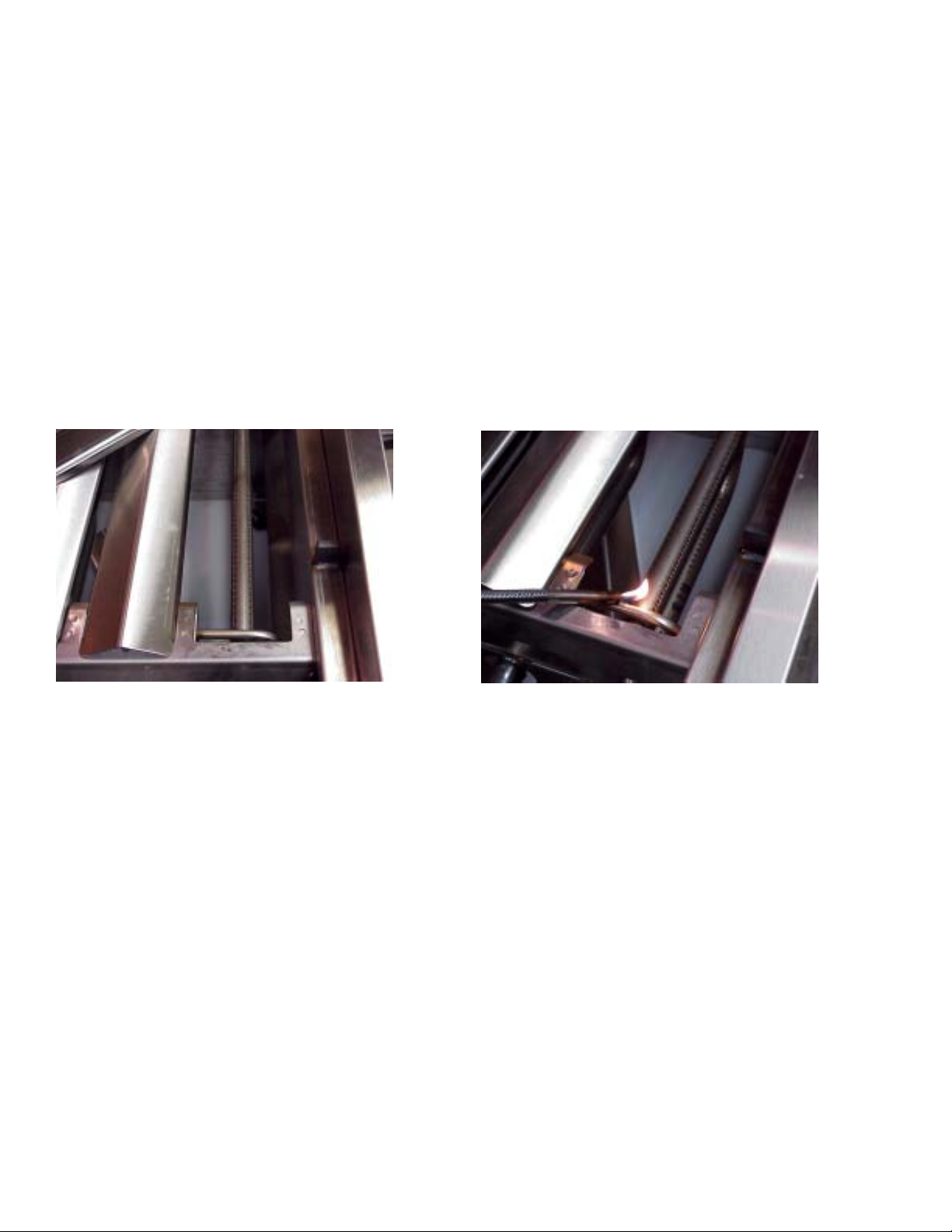
SMB 600 Series Models without safety pilot
a.) Turn all burners to OFF.
b.) Remove the top grid(s).
d.) Turn the runner tube valve to ON.
e.) Light the runner tube through the gap in the front of the coal support as shown.
Note: If the runner tube does not light, wait a few seconds, then try again.
f.) Replace the top grid(s).
Push and turn the burner valves to operate the individual burners as needed.
g.) If any burner fails to light from the runner tube, shut off all the burners and the runner
tube. Do not attempt to re-light for five minutes after shutdown. Repeat steps a thru f.
If unit still fails to operate properly, contact authorized service personnel.
Broiler Shut Down
Turn all burners to OFF.
Turn the runner tube valve to OFF.
L25-001 REV 1 (11/02)
Page 8

RMB 600 Series -S Models with safety pilot
1. Turn all burners to OFF.
2. Remove the top grid.
3. Remove a radiant.
4. Turn the shut off valve to ON.
5. Press and hold the reset (blue) button on the safety pilot valve. Wait 15–30 seconds. Light the runner
tube. DO NOT release the reset button.
NOTE: If the runner tube does not light, wait a few seconds, then try again.
NOTE: When lighting the runner tube for the first time after connecting the unit to the gas source, the light
time will probably increase to 1–2 minutes.
6. Wait an additional 15–30 seconds. Release the reset button. The runner tube should remain lit.
NOTE: If the runner tube fails to ignite, repeat step 5. If the runner tube fails to ignite after three
attempts, contact an authorized MagiKitch’n service agent.
7. Replace the radiant and top grid.
8. Push and turn the burner valves to operate the individual burners as needed.
Broiler Shut Down
1. Turn the shut off valve to OFF.
2. Turn all burners to OFF.
Top Grid
Radiant
Safety Pilot Valve
(located under
shelf)
Runner Tube
Thermocouple
(located on far
end of runner tube)
Off
On
Reset Button
Safety Pi lot Val ve
Shut-off
Valve
SMB 600 Series -S Models with safety pilot
Lighting and shut down of these models is identical to that of the RMB-S models except that there
are no radiants to be removed. Simply light the runner tube by inserting the ignition device through
the gap between the front burner support and the coal support as shown in the lighting instructions
for the SMB 600 Series Models without safety pilot.
L25-001 REV 1 (11/02)
Page 9

5. INITIAL SET-UP
All Models
PROPER SET UP OF THE BROILER - After the installation of the broiler by a qualified
technician, a thorough cleaning is necessary. After this cleaning, be sure the broiler is set up
properly.
TOP GRID - Your top cooking grid has two positions, either flat or tilted. Whenever you are
broiling, you must use the tilted position. This allows grease to drain into the front trough,
reducing both smoke and flare-up. Simply push down on the top grid handle and pull forward to
set the tilted position. The flat position should be used only to heat soups and sauces, etc. in
pots, and never to broil. For the flat position, just reverse the tilted grill procedure, by pushing
down and back.
L25-001 REV 1 (11/02)
Page 10

RMB 600 Series models
STAINLESS STEEL RADIANT - It is very important that the stainless steel radiants are placed
over the burners. This will provide radiant heat and protect the burners from dripping grease.
PREHEATING - It is necessary to preheat a cold broiler each time before cooking. The
recommended time is 3-5 minutes for radiant style charbroilers, at which time the cooking grid
should be hot enough to cook on without sticking, and will produce the proper searing effect.
SMB 600 Series models
COAL SUPPORT - The coal support must be installed so that it is pushed against the back wall
of the unit. This creates an air gap over the runner tube to allow proper ventilation.
L25-001 REV 1 (11/02)
Page 11

COALS - Use only Magicoals supplied by MagiKitch'n. Do not use lava rock or other
replacement coals. They do not perform as well or last as long as the Magicoals that were
designed for this application. Place the coals evenly across the surface of the coal support. Do
not pile them up. This will cause excessive flare up, reduce ventilation, and cause overheating
of the valves and other components.
PREHEATING - It is necessary to preheat a cold broiler each time before cooking. The
recommended time is 15-20 minutes for coal style charbroilers, at which time the cooking grid
should be hot enough to cook on without sticking, and will produce the proper searing effect.
All Models
FLARE-UP - A certain amount of flare-up is desirable when you are charbroiling in order to
flavor your products. However, excess flare-up will burn your products and leave a bitter taste.
With flare-up, one simple formula holds true. The hotter the broiler and the higher the fat
content of the food, the more flare-up you will have. Conversely, the lower the heat and lower
the fat content, the less flare-up you will have.
FLARE-UP PROBABILITY CHART
Heat Level High Fat Content Low Fat Content
High Heat High Moderate
Low Heat Moderate Low
L25-001 REV 1 (11/02)
Page 12

6. CLEANING AND MAINTENANCE
DAILY CLEANING AND MAINTENANCE
TOP GRID - The top grid can be cleaned in numerous ways. The recommended procedure is to
remove the grid and clean the frame, tubes and angles on front, sides and back with steel wool.
The rods need only be scraped free of all cooking debris, especially the underside of the rods,
using the MagiKitch’n scraper provided. The light oily sheen will aid in cooking, acting like a
seasoned iron skillet.
OUTER SIDES AND FRONT - The outer sides and front are stainless steel. Any reputable
cleaner can be used to clean these surfaces.
INNER COOKING AREA - These surfaces are also stainless steel. A paste type oven cleaner
will work best to clean them, but be sure to remove all residues before you resume cooking
operation. The grease collection pan should be emptied daily and the grease disposed of
properly.
WATER TUB – The water tub is designed to reduce flair-up and to eliminate flash back, which
is common on radiant style charbroilers. Flaming grease which drips down will extinguish as
soon as it hits the water. The water tub should never be allowed to run dry and should be
emptied daily and the grease disposed of properly.
Maintaining a clean, well-kept broiler will ensure long-lasting cooking performance and prolong
it’s life.
WEEKLY CLEANING MAINTENANCE
Generally, with this style broiler, you can follow the directions for daily cleaning. However, your
top grid can be soaked in a detergent degreasing solution weekly or monthly. After this
soaking, your grid will need to be thoroughly rinsed with fresh water and then re-seasoned.
7. IMPORTANT OPERATION INSTRUCTIONS RECAP
1. Always cook in a tilted position. This will allow excess grease to drain into the front grease
trough and reduce smoke and flare-up.
2. Keep the top cooking grids clean, especially the underside of the rods. This will unsure that
the grease will drain toward the front grease trough.
Remember the following formula for flare-up:
High Heat + High Fat Content = Maximum Flare-up
Low Heat + Low Fat Content = Minimum Flare-up
L25-001 REV 1 (11/02)
Page 13

8. TYPICAL 600 SERIES ILLUSTRATION ( Model RMB 636 shown )
Note: Your unit may vary from this typical diagram.
L25-001 REV 1 (11/02)
Page 14

8. TYPICAL SMB 600 SERIES ILLUSTRATION (Model SMB 636 shown)
Note: Your unit may vary from this typical diagram.
L25-001 REV 1 (11/02)
Page 15

9. ACCESSORY / PARTS LIST FOR RMB/SMB 600 SERIES MODELS
Not all parts are illustrated, nor are all parts are listed. If you need a part that is not listed here, call
MagiKitch'n for a quote. Always have your model and unit serial numbers available when phoning
or ordering.
THESE PARTS SOLD THRU OUR DEALER NETWORK ONLY.
Ref.
No.
1
2
3
4
5
6
7
8
9
10
11
12
13
Description Ref.
Top Grid, Standard
Radiant
Burner
Burner retaining clip (not shown)
Runner tube (not shown)
Water Tub, Left Hand
Water Tub, Right Hand
Grease Box
Leg, 6” (not shown)
Caster, 6” (not shown)
Knob, main burner
Knob, runner tube
Scraper (not shown)
No.
23
24
25
26
27
28
29
30
31
32
33
34
35
Description
Gas valve, main burner
Gas valve,runner tube (not shown)
Orifice, main burners (not shown)
Orifice, runner tube (not shown)
Manifold assembly (not shown)
Manifold heat shield
Inner heat shield (not shown)
Inner front (not shown)
Front burner support
Outer side
Inner side
Side baffle
Side baffle support (not shown)
14
15
16
17
18
19
20
21
22
L25-001 REV 1 (11/02)
Brush (not shown)
Regulator
Utility bar
Service shelf
Service shelf support (not shown)
LH Frame mtg brkt (not shown)
RH Frame mtg brkt (not shown)
Grease trough
Outer front
36
37
38
39
40
41
42
43
44
45
46
Top grid center support (not shown)
(48/60/72 only)
Outer back (not shown)
Inner back
Back stiffener (not shown)
Back splash liner
Rear burner support
Shelf
Inner bottom (FM only, not shown)
Outer bottom (not shown)
Coal support (see SMB illustration)
Coals (see SMB illustration)
Page 16

10. WARRANTY
ORIGINAL EQUIPMENT WARRANTY
(For U.S. and Canada)
MagiKich’n warrants to each original Buyer that its electrically-heated or gas-fired charbroilers /
outdoor grills will be free from defects in material and workmanship for the period specified below.
MagiKitch’n’s obligation under this warranty shall be limited to replacing or repairing, at its option, any
part found to be defective within the specified warranty period.
PRODUCT WARRANTY PERIOD
One (1) Year Limited Parts and Labor for Indoor Charbroilers
60 Day Limited Parts and Labor for Outdoor grills
The warranty period begins upon the earlier of the date of installation or 90 days after shipment of
the covered product. Any labor expense or part failure incurred after the warranty period will be the
responsibility of the end user. MagiKitch’n agrees to pay any authorized Blodgett service agency
within the United States or Canada for any labor required to repair or replace, at MagiKitch’n’s
option, any part which proves to be defective due to defects in material or workmanship during the
warranty period. This warranty includes travel time not to exceed two (2) hours and mileage not to
exceed one hundred (100) miles, round trip.
This warranty does not cover any defect due to, or resulting from, ordinary wear and tear, handling,
abuse, misuse, improper ventilation, or harsh chemical action, nor shall it extend to any unit from
which the serial number has been removed or altered, or modifications made by unauthorized service
personnel or damage by flood, fire or other acts of God. Adjustments such as calibrations, leveling,
tightening of fasteners or plumbing connections normally associated with original installation are the
responsibility of the dealer or installer and not that of the MagiKitch’n. Briquettes, bottom grates &
burner covers are considered consumables and have a warranty of 6 months only.
MagiKitch’n shall not be liable, directly or indirectly, under any circumstances for consequential or
incidental damages, including, but not limited to: (i) any loss of business or profits; and (ii) labor,
material or other charges, claims losses or damages incurred or suffered from, in connection with or in
consequence of the working upon, alteration, or repair of any such defective products or parts by
persons or firms other than MagiKitch’n.
THIS WARRANTY AND THE OBLIGATIONS ASSUMED BY MAGIKITCH’N ARE EXCLUSIVE AND
IN LIEU OF ALL OTHER LIABILITIES AND WARRANTIES, EXPRESS OR IMPLIED. MAGIKITCH’N
MAKES NO REPRESENTATION OR WARRANTY OF ANY KIND, EXPRESS OR IMPLIED, AS TO
MERCHANTABILITY, FITNESS FOR A PARTICULAR PURPOSE, OR ANY OTHER MATTER WITH
RESPECT TO THE PRODUCTS SOLD HEREUNDER, WHETHER USED ALONE OR IN
COMBINATION WITH OTHER EQUIPMENT. This warranty gives buyer specific legal rights, and
buyer may have other rights which vary from state to state.
IMPORTANT NOTICE
The end-user purchasing a MagiKitch’n charbroiler or grill to which this warranty applies is urged to
return the purchaser registration card included in the owner's document package. Upon the return
of the registration card the warranty period will commence as provided above. If such registration
L25-001 REV 1 (11/02)
Page 17

card is not returned, then the warranty period will be deemed to have commenced on the date of
invoice for the particular oven to the dealer or other intermediate customer, which may have the
effect of reducing substantially the duration of the warranty period.
MAGIKITCH’N
P.O. BOX 501
CONCORD NH 03302-0501
509 ROUTE 3A
BOW NH 03304
800-258-3708
603-225-6684
FAX 603-225-8497
KEEP THIS LITERATURE FOR YOUR RECORDS. WRITE YOUR MODEL AND SERIAL NUMBERS IN
THE BOX ON THE FRONT COVER OF THIS MANUAL FOR FUTURE REFERENCE.
THIS WARRANTY CANNOT PROTECT YOU UNLESS YOUR MAGIKITCH’N APPLIANCE
IS REGISTERED AT THE FACTORY. FOR YOUR OWN PROTECTION, MAIL
ACCOMPANYING CARD WITHIN TEN DAYS AFTER THIS APPLIANCE HAS BEEN
INSTALLED, OR WARRANTY WILL BE VOID
L25-001 REV 1 (11/02)
Page 18

L25-001 REV 1 (11/02)
P.O. BOX 501
CONCORD NH 03302-0501
509 ROUTE 3A
BOW NH 03304
800-258-3708
603-225-6684
FAX 603-225-8497
WWW.PITCO.COM
 Loading...