


MODEL HWG40
MODEL HWG20
GAS FIRED
COMMERCIAL
& INDUSTRIAL
PRESSURE
WASHER
HEATERS
INSTRUCTION
MANUAL
V3.02
For heaters equipped with
ProSafe II control and
24V electronic ignition
(HSI)
or 24V standing pilot

this page was intentionally left blank

TABLE OF CONTENTS
1.0 INTRODUCTION............................................................................................1
2.0 IMPORTANT OPERATING CONDITIONS....................................................2
3.0 SAFETY .........................................................................................................2
4.0 INSTALLATION
4.1 LOCATION.........................................................................................3
4.2 MOUNTING ........................................................................................3
4.3 GAS SUPPLY ....................................................................................3
4.4 VENTING............................................................................................3
4.5 AUTOMATIC VENT DAMPER...........................................................3
4.6 POWER VENTER ..............................................................................4
4.7 FLOW SWITCH..................................................................................4
4.8 INLET PLUMBING .............................................................................4
4.9 OUTLET PLUMBING .........................................................................4
4.10 ELECTRICAL CONNECTIONS .........................................................5
5.0 PRE-OPERATION CHECKS
5.1 FLUSH DEBRIS FROM THE SYSTEM .............................................7
5.2 INITIAL POWER UP ..........................................................................7
5.3 CHECK FLOW SWITCH & AUTOMATIC VENT DAMPER...............7
5.4 BLEED OFF AIR ................................................................................7
5.5 LIGHTING THE PILOT BURNER ......................................................7
5.6 CHECK IGNITION OF MAIN BURNERS...........................................8
PROSAFE II CONTROL
6.0
6.1 TEMPERATURE SETTING ..............................................................9
6.2 POWER INDICATOR......................................................................10
6.3 HEAT ON INDICATOR ...................................................................10
6.4 REQUEST FOR HEAT INDICATOR...............................................10
6.5 PURGE DELAY ON INDICATOR ...................................................10
6.6 FLOW ON INDICATOR ..................................................................10
6.7 THERMOSTAT INDICATOR ..........................................................10
6.8 EXTERIOR CONTROL INDICATOR ..............................................10
6.9 FLUE STATUS INDICATOR...........................................................11
6.10 DAMPER OPEN INDICATOR.........................................................11
6.11 POWER VENT INDICATOR ...........................................................11
PROSAFE II ERROR & WARNINGS
7.0
7.1 ERROR CONDITIONS .....................................................................12
7.2
WARNING CONDITIONS ................................................................12
8.0 ELECTRONIC IGNITION OPERATION.......................................................13
9.0 MAINTENANCE
FLOW SWITCH
9.1
RELIGHTING THE PILOT BURNER ...............................................14
9.2
CARE OF MAIN BURNERS
9.3
CLEANING HEATER COIL OF SCALE
9.4
10.0 HELPFUL INFORMATION
COIL CONDENSATION
10.1
COIL SCALING
10.2
10.3 FREEZING CONDITIONS ................................................................15
USE OF ACIDS ................................................................................15
10.4
COIL TEST
10.5
TERMINAL CONNECTIONS TO
10.6
11.0 TROUBLESHOOTING ...............................................................................16
PARTS LIST
WIRING DIAGRAM
11.0 SPECIFICATIONS......................................................................................23
..............................................................................................
................................................................................
............................................................
..........................................
...................................................................
................................................................................
.......................................................................................
PROSAFE II ...................................
....................................................................................
14
14
14
15
15
15
15
19
21

this page was intentionally left blank

1.0 INTRODUCTION
The HWG20 and HWG40 are steel coil type
instantaneous hot water heaters suitable for any low or
high pressure application requiring fast recovery. They
are most suitable for high pressure wash systems
where the high pressure water from the pump may be
fed through the heater, thereby producing hot water
while only cold water is run through the pump. They
may also be used in combination with an insulated
storage tank for a low pressure hot water system.
The durable stainless steel shell of the HWG20 and
HWG40 withstands years of use and will not rust. Both
models are available with either electronic ignition
(HSI) or standing pilot. An automatic vent damper is
available as an option from the factory to save energy
and protect the heater coil from freezing conditions. In
addition, a power venter is available as an option for
sidewall venting of the heater.
The operation of the heater is controlled and monitored
by the
advanced microcontroller that monitors several
For future reference when ordering parts or requesting
service information, please take a moment to record
your heater model number and serial number which
can be found on the certification plate mounted on the
front of the heater.
PROS AFEIIindustrial heater control, an
aspects of the heater operation in order to provide safe
and effective control of the heater. The PROSAFE
control provides visual status to the operator of the
heater through a front panel display on the heater.
Should some condition arise which results in the
heater exceeding its normal operating temperature, the
PROSAFEIIcontrol provides overheat lockout
protection, thus protecting the heater and operator
from the dangers of a heater overheat condition. The
PROSAFEIIcontrol also provides coil protection via a
coil freeze warning should the temperature in the flue
ever drop near the freezing point. The ProSafe
control will effectively and safely control the optional
automatic vent damper, eliminating open/close cycling
while still providing maximum coil protection and
energy savings. The
directly control the optional power venter without
requiring any additional timers or controls. An
electronic sensor with digital display of the current
water temperature is utilized to provide precise control
of the outlet water temperature.
PROSAFEIIcontrol will also
II
II
Model#
Serial#
-
1
-

2.0 IMPORTANT OPERATING CONDITIONS
Failure to comply with any of these conditions invalidates the warranty.
Pressure - The water pressure supplied to the water
inlet of the heater must never exceed the maximum
water pressure rating of the heater. The pressure
regulator supplied with the heater must remain
installed on the heater.
Freezing Conditions - The heater must be protected
from freezing conditions otherwise severe damage to
the heater coil may result. Adequate air supply to the
area housing the heater must be supplied to prevent
the coil freezing from a reverse draft down the heater
vent. If necessary, an automatic vent damper should
be installed. See section 4.4 VENTING for further
information.
3.0 SAFETY
Your heater was designed and constructed with safety
foremost. The following safety precautions should be
taken with your heater:
1) Read and understand this manual before
operating the equipment. Ensure that all
operators of this heater are fully familiar with
the operating and safety procedures contained
in this manual. An untrained operator exposes
him or herself as well as bystanders to potential
harm.
2) Do not modify the equipment in any way.
Unauthorized modification may impair the
function and/or safety of the equipment creating
a potential or real hazard to personnel.
3) The exterior of the heater may become hot
during operation. Avoid contact with the exterior
of the heater.
4) Do not smoke near the heater. Keep open
flame and sparks away.
Gas Installation- Gas piping and installation of these
gas water heaters must be performed by qualified
licensed personnel in accordance with CAN1-B149.1 &
CAN1-B149.2 installation codes and/or local codes.
III
PROSAFE
serviceable item. Do not remove the mounting screws
holding the cover to the box.
Acids, Alkalies, or Abrasive Fluids - Consult factory
before using heater with any of these fluids.
IF AT ANYTIME YOU SMELL GAS, SHUT OFF THE
GAS SUPPLY TO THE HEATER, AND EXTINGUISH
ANY OPEN FLAME. CALL YOUR GAS INSTALLER
IMMEDIATELY.
If the heater is to be incorporated into a high pressure
system, the safety procedures applicable to high
pressure systems should be followed.
I
Control - The heater control is not a user
1) Always hold the gun and extension firmly in
both hands during operation.
2) High pressure spray presents the risk of
injection and severe injury. Always keep clear
of the spray nozzle. Do not direct discharge
stream at people or electrical apparatus.
Always keep clear of moving belts and pulleys.
3)
4) Never disconnect high pressure hose during
operation.
-
2
-

Pressure Tap
Port
0
1
2
3
4
5
6
1
2
3
4
5
6
4.0 INSTALLATION
*** HEATERS MUST BE INSTALLED BY QUALIFIED PERSONNEL ONLY ***
4.1 LOCATION
The water heater contains sensitive electronic
1)
components that must not be exposed to water
spray. Choose a location such that the heater
will not be exposed to water spray of any kind.
Failure to do so may result in damage to
electronic components and void the warranty
on such components.
2) The water heater is approved for installation on
non-combustible material with 6 inches of
clearance from combustible walls. A minimum
clearance of 48 inches is required on the heater
front for access.
3) The water heater must be located in an area
that is protected from the weather and locations
where flooding may occur.
locations that may cause pilot outage.
4) In repair garages, the point of ignition shall be
not less than 4.5 feet (54 inches) above the
floor.
5) The location of the heater should be in an area
away from moving vehicles and should be
provided with sufficient protection and support
to prevent damage.
6) If the heater is being installed with a high
pressure pump, the heater should be installed
in a suitable dry location as near to the high
pressure pump unit as practical to simplify
connecting the water supply lines and electrical
lines between the two units.
4.2 MOUNTING
The heater must be mounted to a solid, noncombustible base. Mounting holes are provided on
the inside bottom of the heater. The HWG40 has
four 1/2” holes while the HWG20 has three 1/2”
holes.
4.3 GAS SUPPLY
1)
Pipe sizing must conform to local and
applicable codes (CGA B149.1 and B149.2).
Natural gas and LP (propane) heaters
2)
incorporate different components such that they
are not interchangeable. Never supply LP
(propane) to a natural gas heater or natural gas
to a LP (propane) heater.
CAUTION: Unlike natural gas, LP (propane)
gas is heavier than air. If pilot outage should
occur, the floor areas should be vented and
blown clear before relighting the pilot.
Avoid drafty
4.4 VENTING
4.5
-
3
-
IMPORTANT:
Licensed gas installer MUST ensure:
– 3.5" W.C. for natural gas heaters or
11" W.C. using an external regulator for LP
–
gas heaters
measured at the Pressure Tap Port on the gas
valve as shown in figure 4.3.1.
Figure 4.3.1
1) Observe C.G.A. Standards B149.1 and B149.2
and local safety codes.
2) The draft hood furnished with the heater must
be attached to the flue outlet without alteration
using the same size vent as the draft hood
outlet (see specifications for flue diameter).
3) For venting in general, do not reduce size of
vent. Reductions in vent sizing for power
venters must be made after the draft hood. For
horizontal runs, maintain 1/4 inch pitch per foot.
Top of stack to be 2 feet above highest part of
roof or nearby obstructions. Provide an
approved cap for the stack outlet. Refer to
C.G.A. standards.
4) Use of type “B” venting is recommended and
must be installed in accordance with C.G.A.
standards B149.1 and B149.2 by qualified
personnel.
5) Provisions for other water heaters and/or other
gas fired appliances within the same enclosure
as the heater must be made to allow for ample
free air to enter the enclosure for combustion
and venting
. Failure to supply adequate free
air may result in the dangerous
accumulation of combustion gas and/or
severe damage to the heater coil, due to
reverse drafting of air down the heater vent.
If necessary, an automatic vent damper or
power venter should be installed.
AUTOMATIC VENT DAMPER
The following instructions, and all instructions in
this manual pertaining to automatic vent dampers,
refer to the Magikist model HWG-AD10 (for the
HWG40) or the HWG-AD7 (for the HWG20)
automatic vent dampers. Other vent dampers are
neither approved not tested for use with the
HWG40 or the HWG20 heaters.

CAUTION: HWG40 and HWG20 heaters with 24
WATER
INLET
P
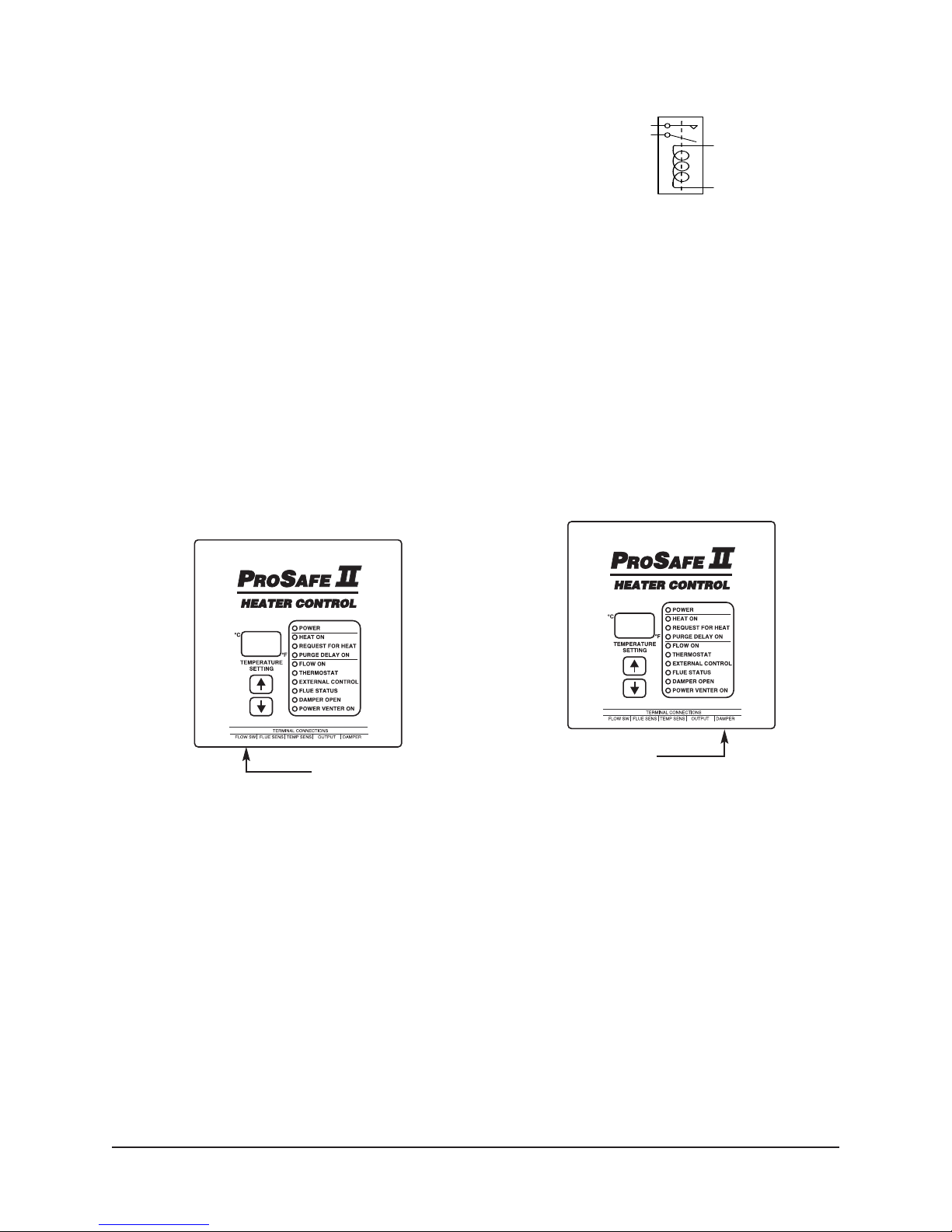
ROSAFE II CONTROL
Flue
Sensor
Temp
Sensor
Flow
Switch
PROSAFE II CONTROL
Flue
Sensor
Temp
Sensor
Flow
Switch
FLOW
SWITCH
PROSAFE II CONTROL
Flue
Sensor
Temp
Sensor
Flow
Switch
volt electronic ignition come equipped for
installation of an automatic vent damper.
Heaters with 24 volt standing pilot must have
an additional or redundant gas valve installed.
Refer to the appropriate C.G.A. standards and
the instructions supplied with the automatic
vent damper.
1) Observe C.G.A. Standards B149.1 and B149.2
and local safety codes.
Ensure that the service switch located on the
2)
motor housing of the automatic vent damper is
at the “AUTOMATIC OPERATION” position.
The “HOLD DAMPER OPEN” position is for
If your heater was supplied without a flow switch,
one must be installed on the water inlet of the
heater for correct operation of the heater. The flow
switch must be a single pole, single throw,
normally open switch capable of switching a
minimum of 1 amp at 24 VAC. The switch must
also have minimum flow rate of 1.0 U.S. gpm. For
most applications where the high pressure output
of a pump is to be fed directly through the flow
switch into the water inlet of the heater,the
maximum pressure and flow rating of the flow
switch must meet or exceed the operating
pressure and gallons per minute (GPM) of the
pump.
service only.
3) The automatic vent damper must be wired
according to the instructions in section 4.10
ELECTRICAL CONNECTIONS.
Failure to do
so will result in incorrect operation of the
automatic vent damper and a potentially
dangerous condition.
4.8 INLET PLUMBING
When facing the front of the heater, the water inlet
is located on the left, top side. If a flow switch was
provided with your heater, the inlet is 3/8” FNPT
connection. If a flow switch was not provided with
your heater, the inlet is a 3/4” MNPT connection.
4) Read the manufacturer’s manual provided with
the automatic vent damper and ensure that all
instructions are followed.
In most applications, the
water inlet of the heater
is connected to the high
4.6 POWER VENTER
The following instructions, and all instructions in
this manual pertaining to power venters, refer to
the Magikist model HWG-PV6B-24 (for the
HWG40) or the HWG-PV4B-24 (for the HWG20)
power venters. Other power venters are neither
approved not tested for use with the HWG40 or
the HWG20 heaters.
1) Observe C.G.A. Standards B149.1 and B149.2
and local safety codes.
2) The power venter must be wired according to
the instructions in the separate document
HWG-PV Power Venter Wiring Instructions.
Failure to do so will result in incorrect
operation of the power venter and a
potentially dangerous condition.
3) Read the manufacturer’s manual provided with
the power venter and ensure that all
instructions are followed.
FLOW SWITCH
4.7
Most heaters are supplied with a flow switch which
you will find installed on the water inlet of the
heater.
heater is normally supplied with a short length of
high pressure hose connected to the water inlet of
the heater that you may use to attach to your inlet
plumbing to.
directly connected to the heater due to the
potential damage that may result from pump
vibration being transferred to the heater.
The plumbing to the water inlet of the heater
should be sized for the flow rate desired in order
to prevent pressure loss. There should be no
unnecessary restrictions in the inlet plumbing.
Length should be kept to a minimum as should
the number of elbows and joints. Teflon tape
should be used to seal all joints.
4.9 OUTLET PLUMBING
Figure 4.8.1
Rigid piping must never be
pressure outlet of a
pump. In such cases,
the direct connection to
the water inlet of the
heater from the pump
must be made with high
pressure hose rated for
the operating pressure
of the pump and the
water outlet temperature
of the heater. Your
When facing the front of the heater, the water
outlet is located at the front, slightly to the right of
the center on the HWG40 the HWG20. The water
outlet is a 3/8” FNPT swivel connection.
Figure 4.7.1
-
4
-

If the water outlet of the
ELECTRICAL
CONNECTION BOX
WITH FLAT LID
REMOVE THESE
4 SCREWS
PROS
AFE II
CONTROL
WATER
OUTLET
P
ROSAFE II CONTROL
Flue
Sensor
Temp
Sensor
Flow
Switch
PROSAFE II CONTROL
Flue
Sensor
Temp
Sensor
Flow
Switch
PROSAFE II CONTROL
Flue
Sensor
Temp
Sensor
Flow
Switch
24VAC
SUPPLY
ELECTRICAL
CONNECTION BOX
black
brown
purple
blue
black*
black*
purple
grey
yellow
white**
ELECTRICAL
CONNECTION BOX
120V to 24V
Transformer
120VAC
SUPPLY
black
white
black
brown
purple
blue
black*
black*
purple
grey
yellow
white**
ELECTRICAL
CONNECTION BOX
METHOD 1
METHOD 2
ELECTRICAL
CONNECTION BOX
Field wiring shown in dashed lines.
Duplicate black wires for convenience.
On some heaters this wire may be brown.
*
**
heater is to be
connected to rigid piping
that is to be distributed
through a facility, it is
recommended that a
short “snubber” hose be
used to connect the
water outlet of the
heater to the rigid
piping. The “snubber”
hose must be rated for
Figure 4.9.1
the operating pressure
of the pump and the
water outlet temperature
of the heater.
The plumbing from the water outlet should be
properly sized for the flow rate desired in order to
prevent pressure loss. As with inlet plumbing,
teflon tape should be used to seal all joints.
4.10 ELECTRICAL CONNECTIONS
The heater is supplied with an electrical
connection box where all electrical connections
are to be made.
The second wiring configuration is used when
installing the heater without a Magikist control
panel. If 24VAC is not available you will need to
mount the supplied transformer to the electrical
connection box and wire the heater according to
method 1 in figure 4.10.2. If the heater is being
added to a system where an existing transformer
has available 24VAC at a minimum of 40VA, you
may wish to simply tap off this transformer and
wire the heater according to method 2.
Figure 4.10.1
Remove the 4 screws holding the flat lid cover to
the front of the electrical connection box as shown
in figure 4.10.1 The inside of the electrical
connection box has been divided into 2 sides. The
right hand side is for the 120 volt connection to a
transformer (if required), while the left hand side is
for all low voltage connections.
There are two typical wiring configurations for the
HWG40 heater. The first configuration is utilized
when the heater is installed in conjunction with a
Magikist control panel such as the CPTX
shutdown control panel.
connections including power for the heater are
For this configuration, all
timed
made between the heater and the control panel.
(the only exception to this is the optional power
venter). Please refer to the wiring diagram
supplied with the Magikist control panel for the
most up to date instructions on wiring the heater
to the control panel. For connections to the power
venter, refer to the power venter wiring
instructions later on in this section.
Figure 4.10.2
Even though in most cases it is not recommended
that the 24vac supply be earth grounded, if the
24vac supply is to earth grounded then the earth
ground MUST be connected to the black wire.
The EXTERNAL CONTROL connections (purple
wires) provide an external means of enabling or
disabling the heater. The EXTERNAL CONTROL
connections are wired together at the factory,
thereby always enabling the heater. For
installations that utilize a Magikist control panel,
follow the wiring diagram supplied with the control
panel for the EXTERNAL CONTROL connections.
For installations that do not utilize a Magikist
-
5
-
control panel, the EXTERNAL CONTROL
Relay with
24VAC coil
to black wire
of ProSafe II
to blue wire
of ProSafe II
contacts of
relay follow
open/close
of flow switch
connections may be left as is or they may be
wired to an external switch, relay, or contactor.
The switch will then act as an overriding master
enable/disable for the heater. For example, the
external switch may be used to provide a cold
water rinse. Likewise, a keyswitch could be used
to prevent unauthorized use. Alternately, if
connected to the auxiliary contact of the motor
contactor for the high pressure pump, the heater
will be disabled whenever the pump is shut down.
The switching device must be a single pole switch
with a minimum rating of 100mA at 24 VAC.
These wires can only be switched, external
power must NEVER be applied to the
EXTERNAL-CONTROL purple wires
.
If your heater was provided with a flow switch, it is
already connected to the
PROSAFEIIcontrol. If
the heater was not supplied with a flow switch, the
flow switch installed in section 4.7 must be
connected to the flow switch terminal connection
located at the bottom of the
(see figure 4.10.3).
External power must NEVER
PROSAFEIIcontrol
be applied to the flow switch terminal
connections.
Figure 4.10.4
If a Magikist automatic vent damper is installed,
locate the damper terminal connection located at
the bottom of the
PROSAFEIIcontrol (see figure
4.10.5) . Remove the jumper plug and connect the
damper cord to the damper terminal connection
(see section 10.6 TERMINAL CONNECTIONS TO
PROSAFE II for important information on
connecting and disconnecting electrical
connectors to the
PROSAFEIIcontrol). This
procedure must be followed if an automatic
vent damper is installed, otherwise the damper
will not be controlled properly and a
potentially dangerous situation may arise.
If an
automatic vent damper is not installed, the jumper
plug must remain installed on the damper terminal
connection.
Flow switch
terminal connections
Figure 4.10.3
The EXT-FLOW connection (blue wire) provides
an external signal as to whether the flow switch is
opened or closed. For installations that utilize a
Magikist control panel, follow the wiring diagram
supplied with the control panel for the EXT-FLOW
connection (blue wire). For installations that do not
utilize a Magikist control panel and another
component of your system requires the flow
switch for some control aspect, the black wire and
the EXT-FLOW blue wire may be used to drive a
relay whose operation will then follow that of the
flow switch. When the blue and black wires are
connected to the 24 VAC coil of the relay (as
shown in figure 4.10.4), the contacts of the relay
will follow the opening and closing of the flow
switch.
Never connect the blue and black wires
together.
terminal connections
Damper
Figure 4.10.5
If a Magikist power venter is installed, the power
venter must be wired to the
PROSAFEIIcontrol
according to the separate document HWG-PV
Power Venter Wiring Instructions.
-
6
-

5.0 PRE-OPERATION CHECKS
THE FOLLOWING PRE-OPERATION CHECKS MUST BE CARRIED OUT, PREFERABLY BY A
LICENSED GAS FITTER, AFTER INSTALLATION OF THE HEATER AND BEFORE OPERATION.
5.1 FLUSH DEBRIS FROM THE SYSTEM
During shipment and installation of your heater,
debris may accumulate that should be removed
before operating your heater. Following are steps
that should be taken to remove any debris from
the heater and the water inlet and outlet plumbing.
1) If your heater is part of a high pressure system,
remove any spray nozzle(s) from the wash
gun(s) attached to the water outlet of the
heater. If your heater is part of a low pressure
system direct the water output of the heater to
a drain.
2) Run water through the heater for 5 to 10
minutes by either operating your high pressure
pump or turning on the water supply to the
water inlet of the heater.
3) Once complete the spray nozzle(s) may be
reinstalled or the water output reconnected.
5.2 INITIAL POWER UP
With the gas supply still off, power-up the heater
by energizing the power source to the heater. The
power-up state of the
indicated by the buzzer sounding and the
temperature setting displaying 888. Following
power-up, the POWER and FLUE STATUS
indicators on the
on. The status of the other indicators depends on
the current state of various inputs to the control.
Refer to section 6.0 PROSAFE II CONTROL for a
detailed explanation of the indicator lights of the
PROSAFE
5.3 CHECK FLOW SWITCH &
AUTOMATIC VENT DAMPER
Before operating your heater, the flow switch and
the automatic vent damper must be checked to
ensure that they are operating correctly. If your
heater does not have an automatic vent damper
installed, the following sequence regarding the
DAMPER-OPEN indicator will not apply as the
DAMPER-OPEN indicator will always be on.
If the FLOW indicator does not follow the steps
below, the flow switch may need adjustment.
Refer to section 9.1 FLOW SWITCH for
instructions on adjusting the flow switch. If the
DAMPER-OPEN indicator does not follow the
steps below, refer to section 11.0
TROUBLESHOOTING.
1) Turn on the high pressure pump or other
I
I
control.
PROS AFEIIcontrol is
PROSAFEIIcontrol should be
source supplying water to the heater such that
water is flowing through the heater. The FLOW
indicator on the
on. If an automatic vent damper is installed, the
DAMPER-OPEN indicator will turn on
approximately 15 to 20 seconds after the
FLOW indicator has turned on.
2) Next, close the trigger gun or turn off the pump
or other source supplying water to the heater
such that there is no water flow through the
heater. The FLOW indicator on the
control should turn off.
3) Repeat these steps 5 to 10 times to ensure that
when there is water flow through the heater that
the FLOW indicator is on, and when there is no
water flow through the heater that the FLOW
indicator is off.
4) Finally, turn off the pump or other source
supplying water to the heater such that there is
no water flow through the heater and the FLOW
indicator turns off. If an automatic vent damper
is installed the DAMPER-OPEN indicator will
turn off after approximately a 5 minute period.
For the automatic vent damper to operate
correctly, power to the heater must remain on.
Removing power from the heater may result in
the automatic vent damper being left in an
open position before the
has had the opportunity to close the damper. If
your heater is equipped with an automatic
vend damper, ensure that the DAMPER-OPEN
indicator is off before powering down the
heater.
BLEED OFF AIR
5.4
As with any new gas installation, the gas lines
supplying the heater must be bled of air.
must be carried out by qualified personnel
only. This step must be completed before
proceeding to the next step.
LIGHTING THE PILOT BURNER
5.5
(STANDING PILOT HEATERS ONLY)
CAUTION: Should pilot outage occur, wait 5
minutes before relighting to clear combustion
chamber of accumulated gas. If an automatic
vent damper is installed, you must also move
the service switch on the motor housing of the
vent damper to “HOLD DAMPER OPEN”
position and wait 5 minutes before relighting
(return switch to “AUTOMATIC OPERATION”
PROSAFEIIcontrol should turn
PROSAFE
PROSAFE
III
I
control
II
This
-
7
-

once relighting procedure is complete).
Because LP (propane) gas is heavier than air,
heaters utilizing these gases should have the
floor areas vented and blown clear before
relighting the pilot.
WARNING:
IF YOU SMELL GAS, SHUT OFF THE GAS
SUPPLY TO THE APPLIANCE AND
EXTINGUISH ANY OPEN FLAME. IF THE
ODOUR PERSISTS, CALL YOUR GAS
INSTALLER IMMEDIATELY.
ADVERTISSEMENT:
SI UNE ODEUR DE GAZ EST DÉCELÉE,
COUPER L’ALIMENTATION EN GAZ DE
L’APPAREIL ET ÉTEINDRE TOUTES LES
FLAMMES. SI L’ODEUR PERSISTE, AVERTIR
IMMÉDIATEMENT LE FOURNISSEUR DE GAZ.
To light the pilot, turn the knob on the combination
gas valve from “off” to the “pilot” position. While
pressing down on the knob, light the pilot. Once lit,
hold down the knob (approximately 30 seconds)
until pilot remains lit when the knob is released.
5.6 CHECK IGNITION OF MAIN BURNERS
1) Ensure that the POWER and FLUE STATUS
indicators on the
PROSAFEIIcontrol are both
on. If a automatic vent damper is NOT installed
the DAMPER OPEN indicator should be on. If a
power venter is NOT installed the POWER
VENTER ON indicator should be on. For
installations that do NOT utilize a Magikist
control panel and have wired the EXTERNAL
CONTROL to an external switch, relay, or
contactor, you will need to perform the action
necessary to turn the EXTERNAL CONTROL
indicator on.
2) If the THERMOSTAT indicator is not on, press
the up arrow button located below the
temperature setting display on the
PROSAFE
control to increase the desired water outlet
temperature, until the the THERMOSTAT
indicator turns on.
3) FOR ELECTRONIC IGNITION HEATERS:
Turn the switch on the combination gas valve
from “off” to “on”.
FOR STANDING PILOT HEATERS: Turn the
knob on the combination gas valve from “pilot”
to “on”. On new installations, the pilot may be
extinguished when moving the knob from “pilot”
to “on” initially due to air inside the gas valve. If
this occurs, repeat the steps in section 5.5.
FLOW ON indicator will turn on once flow is
started. If an automatic vent damper is
installed, the the DAMPER-OPEN indicator will
turn on approximately 15 to 20 seconds after
the FLOW ON indicator is on. If a power venter
is installed, the POWER VENTER ON indicator
will turn on once air flow in the power venter is
proven.
With FLOW ON, THERMOSTAT, EXTERNAL
5)
CONTROL, FLUE STATUS, DAMPER OPEN,
and POWER VENTER ON indicators all on, the
REQUEST FOR HEAT and HEAT ON
indicators will turn on. The main burners should
light within a few seconds. If the main burners
do not light, see section 11.0
TROUBLESHOOTING
6) Close the wash gun or shut off the water supply
to the heater. The FLOW ON indicator will turn
off and the main burners should go off within 10
seconds.
For complete shutdown of the main burners,
including the pilot, turn the switch or knob on the
combination gas valve to “off” position.
WARNING:
RISK OF INJECTION OR SEVERE INJURY. KEEP
CLEAR OF NOZZLE. DO NOT DIRECT DISCHARGE
STREAM AT PERSONS. THIS EQUIPMENT IS TO BE
USED ONLY BY TRAINED OPERATORS
ADVERTISSEMENT:
RISQUE D’INJECTION ET DE BLESSUREES
GRAVES. SE TENIR À L’ÉCART DU JET. NE PAS
DIRIGER LE JET DE SORTIE VERS D’AUTRES
PERSONNES. CONFIER L’UTILISATION DE CE
MATÉRIEL À UN OPÉRATEUR QUALIFIÉ.
WARNING:
IF YOU SMELL GAS, SHUT OFF THE GAS SUPPLY
TO THE APPLIANCE AND EXTINGUISH ANY OPEN
II
FLAME. IF THE ODOUR PERSISTS, CALL YOUR GAS
INSTALLER IMMEDIATELY.
ADVERTISSEMENT:
SI UNE ODEUR DE GAZ EST DÉCELÉE, COUPER
L’ALIMENTATION EN GAZ DE L’APPAREIL ET
ÉTEINDRE TOUTES LES FLAMMES. SI L’ODEUR
PERSISTE, AVERTIR IMMÉDIATEMENT LE
FOURNISSEUR DE GAZ.
If the water inlet of the heater is connected to a
4)
high pressure pump, start the pump and open
the trigger gun to allow water flow through the
heater. If the water source for the heater is not
a pump, open the source of water so that water
flows through the heater. In either case the
-
8
-
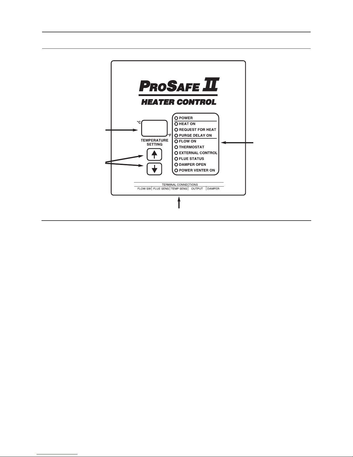
Current desired outlet
temperature setting.
Dot indicates °C or °F.
Use up and down arrows
to adjust current desired
outlet temperature.
6.0
PROSAFE
I
III
CONTROL
Indicators provide
operational status
of heater.
Connections to ProSafe II
The HWG20 and HWG40 heaters are designed to
provide hot water on demand at a given temperature
setting. These heaters will automatically regulate the
temperature of the outlet water to that which you
desire by cycling on and off as required. Because
these heaters are not storage type heaters, they must
also cycle on and off dependent on whether or not
there is water flow.
The operation of the heater is controlled and monitored
by the
advanced microcontroller that monitors several
aspects of the heater operation in order to provide safe
and effective control of the heater. The
control provides visual status to the operator of the
heater through it’s front panel display on the heater. It
also provides the setting for the outlet water
temperature desired from the heater.
Should some condition arise which results in the
heater exceeding its normal operating temperature, the
PROSAFEIIcontrol provides overheat lockout
protection, thus protecting the heater and operator
from the dangers of a heater overheat condition. The
PROSAFEIIcontrol also provides coil protection via a
coil freeze warning should the temperature in the flue
ever drop near the freezing point. Other conditions
which affect the operation of the heater are detected
and displayed to the operator by the
control.
PROS AFEIIindustrial heater control, an
PROSAFE
PROSAFE
II
II
Following is a description of the indicators and their
function on the
6.1 TEMPERATURE SETTING
The temperature setting display on the PROSAFE
II
water temperature from the heater. To change the
temperature setting press the up or down arrow
buttons located below the temperature setting
display. Pressing and holding either of the up or
down arrow buttons will result in the temperature
setting changing slowly until a change of 5°, after
which the setting will change rapidly until either
button is released.
The temperature setting ranges from 40 to 200°F
or 5 to 95
chosen. The current temperature scale is
indicated by a red dot next to either the
°F by the temperature setting display.
The temperature setting display is also used to
indicate any error condition detected by the
PROSAFE
exists the current desired outlet water temperature
is replaced by a flashing error code(s). Refer to
the section 7.0
WARNINGS for diagnosing error conditions.
PROSAFEIIcontrol.
control displays the current desired outlet
C depending on the temperature scale
°
C or the
°
II
control. When an error condition
PROSAFE
I
I
ERRORS &
-
9
-

6.2 POWER INDICATOR
The power-up state to the heater and the PROSAFE
II
control is indicated by the buzzer sounding and
the temperature setting displaying 888 for 1
second. Following power-up, the POWER
indicator on the
on.
6.3 HEAT ON INDICATOR
For electronic ignition (HSI) heaters the HEAT ON
indicator on the
the SmartValve gas valve has provided positive
feedback that the intermittent pilot is lit and the
main section of the gas valve is open.
For standing pilot heaters the HEAT ON indicator
simply follows the on and off action of the
REQUEST FOR HEAT indicator.
6.4 REQUEST FOR HEAT INDICATOR
The REQUEST FOR HEAT indicator on the
PROSAFE
conditions have been met to request that heat be
turned on. The conditions required to request for
heat are flow on, thermostat call for heat, external
control on, flue status good, damper is open,
power venter is on, and purge delay is off.
Essentially if the six indicators FLOW ON,
THERMOSTAT, EXTERNAL CONTROL, FLUE
STATUS, DAMPER OPEN, and POWER
VENTER ON are all on, and PURGE DELAY ON
indicator is off, then REQUEST FOR HEAT will
turn on. Should any of the six indicators turn off,
then REQUEST FOR HEAT will turn off as well.
6.5 PURGE DELAY ON INDICATOR
The PURGE DELAY ON indicator on the PROSAFE
II
control indicates that the heater is currently in
a purge delay. The purge delay is intended to
provide a delay to eliminate rapid on/off cycling of
the gas valve.
The purge delay occurs when there is an end to
the current request for heat and the REQUEST
FOR HEAT indicator turns off. At this point the
PURGE DELAY ON indicator turns on and
remains on for a period of six seconds. During this
period if all conditions required to request for heat
are met, the REQUEST FOR HEAT indicator will
not turn on. If the conditions required to request
for heat remain, the REQUEST FOR HEAT
indictor will turn on once the purge delay is over
and the PURGE DELAY ON indicator turns off.
FLOW ON INDICATOR
6.6
The FLOW ON indicator on the PROS AFE
control indicates whether there is water flow
through the heater or not. If the indicator is on
then there is water flow through heater. If the
indicator is off then there is no flow of water
through the heater.
PROSAFE
PROSAFEIIcontrol indicates that
II
control indicates whether all
I
I
control should remain
If the FLOW ON indicator is flashing slow, the
PROSAFE
there is water flow through the heater and that it
has been continuous for at least 10 minutes. This
warning is strictly for information purposes as it
may indicate a problem with the flow switch, since
the wash gun in high pressure washing
applications is typically not held open continuously
for 10 minutes.
If the wash gun is held open continuously for more
than 10 minutes in your operation, or your heater
is being used in a different application where
water flows through the heater continuously for
more than 10 minute periods, then simply
disregard the flashing FLOW ON indicator. If,
however, the FLOW ON indicator is flashing and
you have
continuously for more than 10 minutes, the flow
switch may not be operating correctly.
should immediately turn off the gas flow to the
main burners by manually turning the knob on
the gas valve from ON to pilot (standing pilot
heaters) or from ON to OFF (for electronic
ignition heaters). This is important as the main
burners of the heater may be continuing to fire
with no water flow through the heater.
Following this, the operation of the flow switch
must be checked. The FLOW ON indicator should
be on when there is water flow through the heater
and off when there is no water flow through the
heater. If the FLOW ON indicator remains on or
continues to flash even after flow through the
heater has stopped, see section 9.1 FLOW
SWITCH for servicing the flow switch.
6.7 THERMOSTAT INDICATOR
The THERMOSTAT indicator on the PROSAFE
control indicates whether the temperature of the
outlet water of the heater is below, at, or greater
than the current temperature setting on the
temperature setting display. If the THERMOSTAT
indicator is on, then the outlet water temperature
of the heater is below the current temperature
setting. If the THERMOSTAT indicator is off, then
the outlet water temperature of the heater is at or
above the current temperature setting.
If the THERMOSTAT indicator is flashing fast and
the temperature setting display is flashing an error
code, the
error condition exists. Refer to section 7.0
PROSAFE
diagnosing error conditions.
I
I
6.8 EXTERNAL CONTROL INDICATOR
The action displayed by the EXTERNAL
CONTROL indicator is dependent on how this
option was setup with your heater. The
EXTERNAL CONTROL is intended to show
whether an external control has enabled or
disabled the heater from operating.
I
I
control is indicating a warning that
not had the wash gun open
PROSAFE
II
I
I
control is indicating that an
ERRORS & WARNINGS for
You
II
-
10
-

For installations that utilize a Magikist control
panel, the EXTERNAL CONTROL indicator
should be on only when the pump is running.
on/off cycling a damper experiences in high
pressure wash systems where wash guns are
opened and closed frequently.
For installations that do not utilize a Magikist
control panel, the EXTERNAL CONTROL, as
supplied from the factory, will always be on. If the
installer has chosen to use the EXTERNAL
CONTROL with and external switch, relay, or
contactor, the EXTERNAL CONTROL indicator
will follow the opening and closing action of that
device.
6.9 FLUE STATUS INDICATOR
The FLUE STATUS indicator provides status as to
one of the key safety components of your heater,
the flue sensor. For normal operation of the heater
The FLUE STATUS indicator remains on.
If the FLUE STATUS indicator is flashing fast and
the temperature setting display is flashing an error
code, the
error condition exists. Refer to section 7.0
PROSAFE
diagnosing error conditions.
If the FLUE STATUS indicator is flashing slow, the
PROSAFEIIcontrol is indicating that a warning
condition exists. Refer to section 7.0
ERRORS & WARNINGS for diagnosing error
conditions.
6.10 DAMPER OPEN INDICATOR
The PROSAFEIIcontrol provides the necessary
control to operate the Magikist damper effectively
and safely. The
damper whenever there is water flow through the
heater. In addition the
close the damper only after there is no water flow
for a preset period of time. This eliminates the
PROSAFEIIcontrol is indicating that an
II
ERRORS & WARNINGS for
PROSAFE
PROSAFEIIcontrol will open your
PROSAFEIIcontrol will
If your heater is not equipped with an automatic
vent damper, the DAMPER OPEN indicator will be
on whenever there is power to the heater.
If your heater is equipped with a Magikist
automatic vent damper, the DAMPER OPEN
indicator is on when the damper is in the open
position and off when the damper is closed or in
the process of opening or closing. Because of the
time required to open and close the damper, there
will be a delay of approximately 15 to 20 seconds
from the time the FLOW ON indicator turns on
(indicating water flow through the heater) and the
DAMPER OPEN indicator turns on.
6.11
POWER VENTER ON INDICATOR
The PROSAFE
control to operate the Magikist power venter
effectively and safely. The
turn on your power venter whenever there is water
flow through the heater. In addition the
II
control will shut off the power venter only after
there is no water flow for a preset period of time.
This eliminates the on/off cycling a power venter
II
experiences in high pressure wash systems where
wash guns are opened and closed frequently.
If your heater is not equipped with a power venter,
the POWER VENTER ON indicator will be on
whenever there is power to the heater.
If your heater is equipped with a Magikist power
venter, the POWER VENTER ON indicator is on
only when air flow in the power venter is proven.
I
I
control provides the necessary
PROSAFEIIcontrol will
PROSAFE
-
11
-

7.0
PROSAFE
I
III
ERRORS & WARNINGS
7.1 ERROR CONDITIONS
The PROSAFEIIcontrol indicates error conditions via
the indicator lights and the temperature setting display.
Error conditions require immediate attention in order to
ensure continued operation of the heater. Whenever
an error condition is present, the heater will not fire.
Some error conditions lockout the operation of the
heater until the error is cleared by a power down/up
sequence. The alarm buzzer sounds on all errors.
Should an error condition arise, the indicator light that
relates to the error condition will flash on and of at a
fast rate. In addtion, the temperature setting display wil
no longer show the desired outlet water temperature,
but instead will display a flashing error code Exx where
xx is the error code.
Please see section 11.0 TROUBLESHOOTING for
diagnosing error conditions.
Table 7.1 - ERROR CONDITIONS
Temperature Setting
Display Flashes
E10 FLUE STATUS Problem with communication to flue
E11 FLUE STATUS Problem with communication to flue
E15 FLUE STATUS Flue overheat condition. Yes
Indicator Light
Flashing Fast Description
sensor (open).
sensor (short).
7.2 WARNING CONDITIONS
The PROSAFEIIcontrol indicates warning conditions
via the indicator lights. Unlike error conditions, warning
conditions do not prevent the heater from firing.
Warning conditions should be attended to promptly in
order to ensure the continued safe operation of the
heater.
Should a warning condition arise, the indicator light
that relates to the warning condition will flash on and of
at a slow rate.
Please see section 11.0 TROUBLESHOOTING for
diagnosing warning conditions.
Requires Power Down/Up
Sequence to Clear
No
No
E20 THERMOSTAT Problem with communication to
temperature sensor (short).
E21 THERMOSTAT Problem with communication to
temperature sensor (short).
E30 REQUEST FOR
HEAT
E31 REQUEST FOR
HEAT
E59 (none) Problem with internal memory. Yes
Table 7.2- WARNING CONDITIONS
Indicator Light
Flashing Slow Description
FLUE STATUS Temperature in flue is near or
below freezing. Water in heater
coil is in danger of freezing and
damaging coil.
FLOW ON Flow has been asserted for more
than 10 minutes.
Problem with OUTPUT driver (open). Yes
Problem with OUTPUT driver (short). Yes
No
No
-12-

8.0 ELECTRONIC IGNITION OPERATION
This section is applicable only to heaters which utilize
electronic ignition (HSI).
When there is a request for heat as shown by the
REQUEST FOR HEAT indicator on the
control, the PROSAFE
gas valve (hereafter referred to as the SmartValve) to
start the ignition sequence. In response the
SmartValve will begin the pilot trial period, where the
SmartValve attempts to light the pilot for a period of 90
seconds. This 90 second period consists of the the
following sequence: hot surface ignitor (HSI) on for 30
seconds; HSI off for 30 seconds; HSI on for an
additional 30 seconds. If the attempt to light the pilot is
successful during the pilot trial period, the main section
of the SmartValve will then energize for main burner
ignition to occur. If the attempt to light the pilot is
unsuccessful after 90 seconds, the SmartValve will
begin a 5 minute delay period before reattempting
another pilot trial period. The SmartValve is a
continuous retry control. Thus it will continuously
repeat the pilot trial period followed by the 5 minute
I
I
control signals the SmartValve
PROSAFE
II
delay period, until the pilot is successfully lit or the
PROSAFEIIcontrol no longer indicates REQUEST
FOR HEAT.
If after successful lighting of the pilot, the SmartValve
detects that the pilot is no longer lit, it will once again
begin the pilot trial period. If the pilot is not relit after 90
seconds, the SmartValve will begin the 5 minute delay
period. Continuous retry will occur as described above.
The HEAT ON indicator of the ProSafe II control
indicates that the SmartValve gas valve has provided
positive feedback that the pilot is lit and the main
section of the gas valve is open. If the REQUEST FOR
HEAT indicator of the PROSAFE
indicator of the the
ON
no indication of what state the SmartValve is in with
regards to it’s continuous retry sequence. In other
words the SmartValve could be in the pilot trial period
(HSI on or HSI off), or the 5 minute delay period.
PROSAFE
II
is lit but the HEAT
I
I
is not lit, there is
-
13
-

9.0 MAINTENANCE
9.1 FLOW SWITCH (MODEL HPFS38)
On heaters where the mineral content of the water
is high or where chemicals or soaps are used, it
may be necessary on occasion to
disassemble the housing
and clean any debris and
build up inside the flow
switch. This maintenance
will allow the magnet to
continue to move smoothly
and freely, and will
eliminate nuisance failures
due to scale buildup. It is
suggested that the flow
switch be inspected and
cleaned as necessary
each time the heater (or
possibly the high pressure
Figure 9.1.1
To adjust the flow switch, the reed switch will need
to be repositioned. The reed switch is housed
inside the cylindrical metal can from which the
jacketed wire comes out. To reposition the reed
switch loosen the friction bolt/nut and slide the
cylindrical metal can in or out such that the FLOW
indicator is on when there is flow and off when
there is no flow through the switch. Retighten the
friction bolt/nut to secure the position of the reed
switch.
9.2 RELIGHTING THE PILOT BURNER
(STANDING PILOT HEATERS ONLY)
CAUTION: Should pilot outage occur, wait 5
minutes before relighting to clear combustion
chamber of accumulated gas. If an automatic
vent damper is installed, you must also move
the service switch on the motor housing of the
vent damper to “HOLD DAMPER OPEN”
position and wait 5 minutes before relighting
(return switch to “AUTOMATIC OPERATION”
once relighting procedure is complete).
Because LP (propane) gas is heavier than air,
heaters utilizing these gases should have the
floor areas vented and blown clear before
relighting the pilot.
WARNING:
IF YOU SMELL GAS, SHUT OFF THE GAS
SUPPLY TO THE APPLIANCE AND
EXTINGUISH ANY OPEN FLAME. IF THE
ODOUR PERSISTS, CALL YOUR GAS
INSTALLER IMMEDIATELY.
ADVERTISSEMENT:
SI UNE ODEUR DE GAZ EST DÉCELÉE,
COUPER L’ALIMENTATION EN GAZ DE
L’APPAREIL ET ÉTEINDRE TOUTES LES
FLAMMES. SI L’ODEUR PERSISTE, AVERTIR
IMMÉDIATEMENT LE FOURNISSEUR DE GAZ.
pump) receives routine
maintenance or service.
Should pilot outage occur, refer to section 5.5
LIGHTING THE PILOT BURNER for instructions
on relighting the pilot burner.
9.3 CARE OF MAIN BURNERS
Due to condensation from heater coils dripping on
the burners, a scale build-up may occur in the
burner jet orifices.
To remove the burner bar from the heater, turn off
the gas to the heater by turning the knob on the
gas valve to the “off” position. For standing pilot
heaters, disconnect the pilot tube and
thermocouple at the gas valve. For electronic
ignition heaters, disconnect the pilot tube and the
electrical connections between the pilot assembly
and the electronic ignition module (take care to
note the connections so that they may be
reconnected correctly). Disconnect the union
joining the burner bar to the modulating gas valve,
and the U-bolt retaining the feed pipe at the
bottom of the heater inside the door. Slide the
burner bar out through the shell opening.
To clean burner jets select the proper size drill for
type of gas involved. Use a pin vise to hold the
drill and ream out each jet orifice by hand
recommended that the burner jets not be removed
from the burner bar except for jets that require
replacing.
size than shown.
HWG40:
#55 drill for natural gas 0-2000ft. (0-610 m)
#56 drill for natural gas 2000-4000ft. (610-1370 m)
#68 drill for LP gas 0-2000ft. (0-610 m)
#70 drill for LP gas 2000-4000ft. (610-1370 m)
HWG20
#52 drill for natural gas 0-2000ft. (0-610 m)
#53 drill for natural gas 2000-4000ft. (610-1370 m)
#63 drill for LP gas 0-2000ft. (0-610 m)
#64 drill for LP gas 2000-4000ft. (610-1370 m)
CLEANING HEATER COIL OF SCALE
9.4
Excessive scale in heater coils can reduce the
recovery rate of the heater and restrict the flow of
water through the heater. Use of hard water
through the heater tends to accelerate scale buildup. Should heater coils develop excessive scale
build-up it may be necessary to use a coil cleaner
to remove the scale build-up. Use only an
approved coil cleaner specially designed for
cleaning scale and mineral deposits from steel
coils, such as Magikist
To clean the heater coil of scale build-up, follow
the directions provided with the coil cleaner. Never
allow the coil cleaner to sit in the coil overnight or
for long periods of time. Always flush out the coil
thoroughly with water after cleaning.
Do not ream out orifices to a larger
MAGIKCOIL de-liming acid.
. It is
-
14
-

10.0 HELPFUL INFORMATION
10.1 COIL CONDENSATION
During the operation of your heater, you may
notice water in the base of the heater or you may
hear the sizzling of water drops falling on the
flames of the main burner. This collection of water
or “dripping” of water is typical in the operation of
all steel coil heaters. It is caused by the products
of gas combustion which produce gaseous carbon
dioxide and water vapour. The water vapour
condenses on the coils which have cold water
running through them. The lower the temperature
of the incoming water, and the higher the rate of
combustion and/or the higher the relative
humidity, the more “drip” that occurs. Over a
period of time this tends to decrease.
If you suspect that the water in the base of the
heater is not from coil condensation, turn the
heater off such that the main burners are not lit
and run water through the heater. The “dripping”
of water from coil condensation will stop after a
short period of time.
10.2 COIL SCALING
Scale build-up in the heater coil can reach a point
where the recovery rate of the heater is reduced
and/or the flow of water through the heater is
restricted. Use of hard water through the heater
tends to accelerate scale build-up. Should scale
build-up reach a point where the operation of the
heater is affected, descaling with an approved coil
cleaner may be required. See section 8.4
CLEANING HEATER COIL OF SCALE for more
information.
10.4 USE OF ACIDS
If acids of any type are used then a form of
downstream chemical injection or suitable check
valve should be used to protect the coil.
10.5 COIL TEST
After manufacture each coil is hydrostatically
pressure tested to 3500 PSI. Each heater also has
a final hydrodynamic leak test performed after
final assembly (with all fittings installed) before the
heater leaves the factory.
10.6 TERMINAL CONNECTIONS TO PROSAFE
Except for the FLOW SW connection, the
PROSAFE
it’s terminal connections. To remove a plug you
must press down on the locking pin and then pull
the plug out. Never use excessive force to remove
the plugs. When reinserting a plug, simply align
the plug with the correct terminal connection and
insert. Plugs are polarized and will only fit into the
correct terminal connection.
I
I
uses lockable polarized plugs for all
III
I
10.3 FREEZING CONDITIONS
Freezing conditions can result in severe damage
to the heater coil. Coils must be drained
completely with compressed air or have antifreeze run through them if they are exposed to
freezing weather. Note that heater coils installed
in a heated building can still freeze. If the building
has a negative pressure cold air will be drawn
down the chimney and could freeze the top of the
coil. This can normally be prevented by the use of
an automatic vent damper.
-
15
Connections to ProSafe II
-

11.0 TROUBLESHOOTING
Symptom Probable Cause Corrective Action
•Heater does not power-up
(POWER indicator on PROSAFE II
control does not turn on).
•Power to heater not turned on.
•24 VAC power not connected to
brown & black wires.
•Turn on power supply to the heater.
•See section 4.10 ELECTRICAL
CONNECTIONS.
•Main burner does not light. •Gas supply turned off.
•Gas valve not in “on” position.
•Pilot burner is not lit or has been
extinguished (standing pilot models
only).
•REQUEST FOR HEAT indicator on
P
ROSAFE II control is not on.
•Main burner does not shut off. •Flow switch misadjusted.
•Incoming gas pressure is too high
•Pilot goes out frequently (standing
pilot heaters only).
•Heater is in location that is too
drafty.
•Pilot assembly requires service.
•Turn on gas supply to heater.
•Turn knob on gas valve to “on”
position.
•Relight pilot burner. See section 5.5
LIGHTING THE PILOT BURNER.
•See section 6.0 P
CONTROL.
•See section 5.3 CHECK FLOW
SWITCH & AUTOMATIC VENT
DAMPER for instructions on
checking the operation of the flow
switch. See section 9.1 FLOW
SWITCH for instructions on
adjusting the flow switch.
•Have gas service personnel check
and adjust supply gas pressure.
•Relocate heater. See section 4.1
LOCATION.
•Have gas service personnel check
operation of pilot assembly and
thermocouple.
ROSAFE II
•Pilot cannot be lit (standing pilot
heaters only).
•Water collecting in the base of
heater.
•FLOW ON indicator is on when
there is no water flow.
FLOW ON indicator is off when
•
there is water flow.
FLOW ON indicator flashes.
•
•Pilot assembly requires service. •Have gas service personnel check
operation of pilot assembly and
thermocouple.
•A fair amount of condensation which
can collect in the base of the heater
is a normal product of the operation
of your heater.
•Flow switch misadjusted. •See section 5.3 CHECK FLOW
Flow switch misadjusted or
•
inoperative.
Warning condition that consistent
•
water flow through the heater has
been detected.
-
16
-
•No action is required. For more
information refer to section 10.1
COIL CONDENSATION.
SWITCH & AUTOMATIC VENT
DAMPER for instructions on
checking the operation of the flow
switch. See section 9.1 FLOW
SWITCH for instructions on
adjusting the flow switch.
This indication is only informative
•
and may not indicate a problem.
Refer to section 6.6 FLOW ON
INDICATOR for more information.

Symptom Probable Cause Corrective Action
EXTERNAL CONTROL indicator is
•
always off.
If the installer of your heater has
•
utilized an external master
enable/disable for the heater (i.e. a
keyswitch to prevent unauthorized
use), then that master
enable/disable is not enabled (i.e.
the switch is not turned on).
Enable the external master
•
enable/disable.
•EXTERNAL CONTROL indicator is
always on.
•FLUE STATUS indicator is
flashing but temperature setting
shows no error and heater
operates correctly.
•DAMPER-OPEN indicator is
always on.
•EXTERNAL CONTROL connections
are not wired correctly.
•The heater is supplied with the
EXTERNAL CONTROL option
bypassed such that the EXTERNAL
CONTROL indicator will always be
on. If your installer has not utilized
an external master enable/disable
for the heater, then it is correct for
the EXTERNAL CONTROL
indicator to be on all the time.
•Warning condition that temperatures
in flue are at or near freezing.
•If an automatic vent damper is not
installed, then this is normal and
correct operation.
•The automatic vent damper may not
have been correctly connected, or
may be jammed due to improper
installation.
•See section 4.10 ELECTRICAL
CONNECTIONS for proper wiring
of the EXTERNAL CONTROL
connections.
•No action required.
•Take necessary steps to increase
temperature in flue so that coil does
not freeze.
•No action required.
•See section 4.10 ELECTRICAL
CONNECTIONS for proper wiring
of an automatic vent damper.
Section 5.3 CHECK FLOW
SWITCH & AUTOMATIC VENT
DAMPER provides instructions to
ensure the damper is operating
correctly.
DAMPER-OPEN indicator is
•
always off.
The service switch on the motor
•
housing of the damper is in “HOLD
DAMPER OPEN” position.
If an automatic vent damper is
•
installed then the jumper plug
required may not be installed.
The automatic vent damper may not
•
have been correctly connected, or
may be jammed due to improper
installation.
-
17
-
not
Move service switch to the
•
“AUTOMATIC OPERATION”
position.
See section 4.10 ELECTRICAL
•
CONNECTIONS for proper wiring
of the heater with and without an
automatic vent damper. Section 5.3
CHECK FLOW SWITCH &
AUTOMATIC VENT DAMPER
provides instructions to ensure the
damper is operating correctly.

Symptom Probable Cause Corrective Action
Temperature setting display
•
flashes E10 and FLUE STATUS
indicator is flashing.
•Temperature setting display
flashes E11 and FLUE STATUS
indicator is flashing.
Temperature setting display
•
flashes E15 and FLUE STATUS
indicator is flashing.
•Temperature setting display
flashes E20 and THERMOSTAT
indicator is flashing.
•Temperature setting display
flashes E21 and THERMOSTAT
indicator is flashing.
•Temperature setting display
flashes E30 and REQUEST FOR
HEAT indicator is flashing.
•Temperature setting display
flashes E31 and REQUEST FOR
HEAT indicator is flashing.
•Temperature setting display
flashes E59.
Communicaton problem with flue
•
sensor (open).
•Communicaton problem with flue
sensor (short).
Overheat condition detected.
•
•Communicaton problem with
temperature sensor (open).
•Communicaton problem with
temperature sensor (short).
•Problem with output driver for gas
valve (open). PROSAFE II is
attempting to energize the gas valve
but is not receiving the correct
internal feedback that the gas valve
is being energized.
•Problem with output driver for gas
valve (short). P
ROSAFE II is not
attempting to energize the gas valve
but is not receiving the correct
internal feedback that the gas valve
is not being energized.
•Problem with internal memory of
PROSAFE II.
Check connection of flue sensor to
•
PROSAFE II. Replace flue sensor if
necessary.
•Check connection of flue sensor to
PROSAFE II. Replace flue sensor if
necessary.
Temperature in flue has exceeded
•
maximum limit. Most common
condition is that main burner of
heater is on with no water flow the
heater. Investigate and correct
immediately.
•Check connection of temperature
sensor to P
ROSAFE II. Replace
temperature sensor if necessary.
•Check connection of temperature
sensor to P
ROSAFE II. Replace
temperature sensor if necessary.
•Contact qualified service personnel.
•TURN KNOB ON GAS VAVLE TO
OFF POSITION IMMEDIATELY.
SHUT OFF GAS SUPPLY TO
HEATER IMMEDIATELY.
EXTINGUISH ANY OPEN FLAME
IMMEDIATELY. Contact qualified
service personnel.
•Contact qualified service personnel.
-
18
-

-
20
-

-
21
-
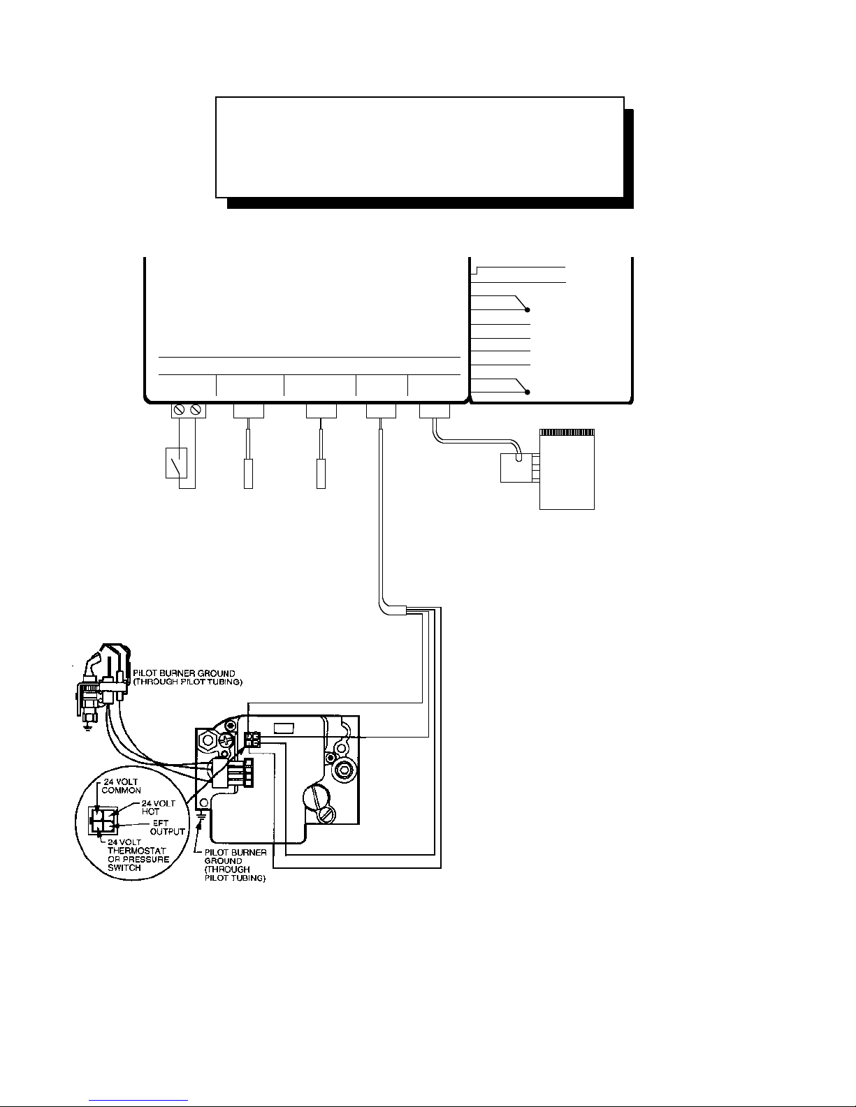
HWG20 & HWG40 Wiring
24 volt hot surface ignition systems
(HSI)
HWG-AD10 (HWG40) or
HWG-AD7 (HWG20)
Automatic Vent Damper (optional)
If not installed then Damper jumper
plug must be installed.
Flue
Sensor
Temp
Sensor
Flow
Switch
PROSAFE II
CONTROL
TERMINAL CONNECTIONS
FLUE SENS TEMP SENSFLOW SW OUTPUT DAMPER
brown
black
24vac
supply**
b
lack*
b
lack*
purple
purple
b
lue
g
rey
yellow
white***
Refer to manual for
wiring of purple, blue,
grey, yellow & white
*
Duplicate black
w
ires for
c
onveni ence
Electrical
Connection
Box
black
red
green
IMPORTANT: If the 24 vac supply
is to be earth grounded, earth
g
round must be connected to
t
he black wire.
**
***On some heaters
this wire may
be brown
white
HWG40
24V Gas Valve
#HWG40-16x24H
Pilot Igniter/Sensor
#HWG40-13NH
-
21
-

HWG20 & HWG40 Wiring
24 volt electronic ignition systems
(intermittent pilot)
Wiring-di agram.cad
HWG20 & HWG40 Wiring
24 volt standing pilot systems
Damper
jumper plug
HWG40 & HWG20
24V Gas Valve
#HWG40-16x24
#HWG20-16x24
Flue
Sensor
TH TR
O
F
F
P
I
L
O
T
TH-TR
O
N
Temp
Sensor
Flow
Switch
PROSAFE II
CONTROL
TERMINAL CONNECTIONS
F
LUE SENS TEMP SENSFLOW SW OUTPUT DAMPER
b
rown
b
lack
black*
b
lack*
p
urple
p
urple
blue
g
rey
y
ellow
R
efer to manual for
w
iring of purple, blue,
g
rey, yellow & white
*
Duplicate black
w
ires for
c
onveni ence
Electrical
Connection
Box
24vac
supply**
IMPORTANT: If the
2
4 vac supply is to be
earth grounded, earth
ground must be
connected to
the black wire.
**
red
green
black
H
WG-AD10N (HWG40) or
H
WG-AD7N (HWG20)
Automatic Vent Damper (optional)
If not installed then Damper jumper
plug must be installed.
F
lue
Sensor
T
emp
Sensor
F
low
Switch
Electronic Ignition Control
#HWG-125
P
ilot Sensor/Ignitor
h
igh voltage lead
Burner Bar Ground
M
V
MV/PV
PV
GND
24V
GND
24V
TH-W
SPARK
P
ROSAFE II
CONTROL
T
ERMINAL CONNECTIONS
FLUE SENS TEMP SENSFLOW SW OUTPUT DAMPER
brown
b
lack
24vac
supply**
black*
black*
p
urple
purple
blue
grey
y
ellow
white***
Refer to manual for
wiring of purple, blue,
grey, yellow & white
*Duplicate black
wires for
convenience
Electrical
Connection
Box
black
red
green
HWG40
24V Gas Valve
#HWG40-16x24R
T
R
T
H
2
34
IMPORTANT: If the 24 vac supply
i
s to be earth grounded, earth
ground must be connected to
the black wire.
*
*
*
**On some heaters
this wire may
b
ebrown
white***
***On some heaters
this wire may
be brown
-
22
-

12.0 SPECIFICATIONS
HWG40
Type ............................................................................................Instantaneous steel coil
Gas supply ..................................................................................Natural (-N models)/LP (-P models)
Coil specifications .......................................................................3/4” I.P.S. steel pipe Sch 80
Maximum recovery capacity (100°F rise)....................................331.9 U.S. gallons per hour
Maximum operating pressure......................................................3000 P.S.I.
Maximum operating temperature ................................................200°F
Minimum water flow rate
Flue outlet size ............................................................................10” diameter
Normal input ratings
0 - 2000 ft (0 - 610 m) ..........................................................395,000 BTU/hour (maximum)
2000 - 4000 ft (610 - 1370 m) ..............................................355,500 BTU/hour (maximum)
Manifold gas pressure
Natural gas...........................................................................3.5” W.C.
LP (propane) gas .................................................................11.0” W.C.
Maximum supply gas pressure
Natural gas...........................................................................14” W.C.
LP (propane) gas .................................................................11.0” W.C.
Flooring type required .................................................................Non-combustible
Shell diameter .............................................................................24”
Width ...........................................................................................32”
Depth...........................................................................................32”
Height (without draft hood)..........................................................46”
Height (with draft hood)...............................................................66-3/4”
Shipping weight...........................................................................418 lbs.
.............................................................1.0 U.S. gallons per minute
HWG20
Type ............................................................................................Instantaneous steel coil
Gas supply ..................................................................................Natural (-N models)/LP (-P models)
Coil specifications .......................................................................3/4” I.P.S. steel pipe Sch 80
Maximum recovery capacity (100°F rise)....................................150 U.S. gallons per hour
Maximum operating pressure
Maximum operating temperature
Minimum water flow rate .............................................................1.0 U.S. gallons per minute
Flue outlet size ............................................................................7” diameter
Normal input ratings
0 - 2000 ft (0 - 610 m)
2000 - 4000 ft (610 - 1370 m) ..............................................180,000 BTU/hour (maximum)
Manifold gas pressure
Natural gas...........................................................................3.5” W.C.
LP (propane) gas
Maximum supply gas pressure
Natural gas...........................................................................14” W.C.
LP (propane) gas .................................................................11.0” W.C.
Flooring type required
Shell diameter .............................................................................16”
Width ...........................................................................................22”
Depth...........................................................................................23”
Height (without draft hood)..........................................................35”
Height (with draft hood)...............................................................50-1/2”
Shipping weight...........................................................................200 lbs.
......................................................
................................................
..........................................................
.................................................................
.................................................................
3000 P.S.I.
°F
200
200,000 BTU/hour (maximum)
11.0” W.C.
Non-combustible
-
23
-

WARRANTY
Magikist heaters are warranted by the manufacturer to be free from defects in material and workmanship for
one year from date of manufacturer's shipment, provided the equipment is installed and operated in accordance
with factory recommendations and instructions. This warranty is limited to repairing or replacing products which
manufacturer's investigation shows were defective at the time of shipment by the manufacturer. This warranty
does not cover normal wear, nor does it cover damage caused by neglect, misuse, accident, faulty installation
or tampering in a manner to impair its normal operation. All products subject to this warranty shall be returned
freight prepaid to Magikist Ltd., Winnipeg, Canada for examination, repair, or replacement.
The express warranty set forth herein is in lieu of all other warranties, express or implied, including without
limitation any warranties or merchantability or fitness for a particular purpose and all such warranties are hereby
disclaimed and excluded by the manufacturer. Repair or replacement of defective products as provided is the
sole and exclusive remedy provided hereunder and the manufacturer shall not be liable for any further loss,
damages or expenses, including incidental and consequential damages, directly or indirectly arising from the
sale or use of this product.
This warranty is subject to the installation and operating conditions as described in this manual. This warranty
does not apply to optional equipment which may have been supplied with your pump. Refer to the warranty
supplied with the optional equipment for information on that equipment's warranty.
Parts originally manufactured by Magikist Ltd. must be used or this limited warranty will be voided. Magikist Ltd.
will be absolved of any liability if parts other than Magikist Ltd. manufactured parts are used.
There are no warranties which extend beyond the description of the face thereof.
-
24
manual-24v-v302
10062006
-
 Loading...