

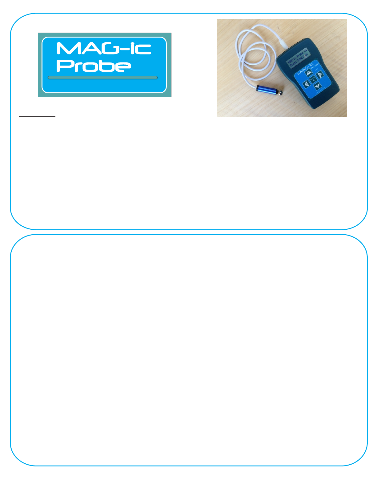
V4.0
Electronic Thickness Gauge
Disclaimer:
WARNING !! - This device uses extremely strong NEODYMIUM magnets. These magnets can cause injury or
damage if misused. KEEP AWAY FROM CHILDREN!!. DO NOT OPEN or USE if you have a pacemaker or
other medical condition that may be affected by magnetic fields. The strong magnetic fields can erase computer
hard drives, magnetic access and credit cards, Use at your own RISK.
MAG-ic Tech or its owners neither assumes nor accepts any liability for damages resulting from the handling or
use of this equipment. With your purchase, the buyer agrees that he/she is responsible for all damages and
injuries caused by the use of this product , which include personal injuries , property damages and any other
damage whatsoever. The buyer must agree with the terms before using the product.
Pay special attention when using this device to measure finished instruments. The probe tip is fabricated from
Delrin and may scratch or leave marks on finished surfaces.
DO NOT DRAG THE PROBE TIP OVER FINISHED SURFACES!! To avoid scratches and marks, you should
slightly lift the probe before moving it. A good method is to lift the tip and place a piece of soft cloth under before
moving and removing the cloth at the new measuring location.
Calibration - a Word about magnetics
This device uses magnets and magnetic sensors to measure the thickness of non-ferrous materials. This
technique is very effective because magnetic fields can penetrate these materials with no attenuation or
deformation. However, as with most technologies, some tolerance and knowledge is required for achieving the
best results.
Ÿ Magnetic fields are strong at the magnet surface and deteriorate rapidly in a non-linear manner as distance
increases.
Ÿ Magnetic fields will vary with changing temperatures.
Ÿ Magnetic and most other sensors are unstable and vary their output with changing temperatures.
Ÿ Friction may cause the inner magnet to not be centered on the probe tip when moving the probe across the
measured object.
Considering the above and following the usage tips will enable you to get the most out of your MAG-ic Probe.
MAG-ic Probe is supplied with 2 magnets. The ½” ball provides the strongest magnetic field and thus the highest
resolution and should always be your first choice. The smaller magnet should only be used when access to the
inside of a finished instrument is limited due to small f-holes etc.
MAG-ic Probe starts with a calibration sequence to detect the magnet size and also to try and compensate for
small variations in field measurement tolerances. This initial calibration is suitable for most quick measuring jobs,
for example where you are making a few measurements, shaping or sanding and then measuring again etc.
Note, MAG-ic Probe can be powered by the USB connection without the power switch turned ON, however
because computer power supplies may have slightly different outputs, MAG-ic Probe was calibrated with the
internal battery connected and power switch in the ON position.
Advanced Calibration.
When preparing for a more serious prolonged measuring session such as mapping a complete top or plate with
many measurements, a two step calibration sequence is advised.
MAG-ic probe is factory calibrated using a precisely machined stepped surface in a temperature controlled
environment. The largest effect that may cause a drift in the measurement value, is from variance in probe
temperature due to heating by the hand of the user.

Advanced calibration continued...
After the initial calibration sequence and before attempting a prolonged measuring session, the
following sequence is advised. The purpose is to perform a calibration only once the probe has reached
a stable temperature.
Hold the probe in your hand in the same way as you would while measuring. Important, do not envelop
the entire probe in your hand, simply hold it just as you would while measuring. Your hand will heat the
probe It may take 3-5 minutes for the probe to reach a stable temperature.
Then perform a re-calibration, by pressing the FUNCTION key and choosing the Re-Calibrate option.
You can also perform a Re-Calibration at any time should you feel the need. Take care to keep the
environmental temperature stable and avoid direct exposure to fans or heater vents.
Additional Information.
There is an additional information source provided by menu option 1 called Ref. It is important to
understand the significance and objective of this option before using it. The Ref option can be
engaged by pressing FUNCTION ^1.
Firstly, the initial calibration procedure, will compensate for differences between your shop
environment and the factory environment where MAG-ic Probe was calibrated. The problem is that
after this calibration your hand may heat the probe causing a small drift in value. This is the reason
for the 2nd calibration as described above. To assist in this 2nd calibration, the Ref option can be
used.
BEFORE performing the 2nd Calibration, invoke the Ref option. The Ref (reference) option shows a
value, normally a negative value, for example -53. This value represents a difference measured in
the conditions of your environment to the factory environment where MAG-ic Probe was calibrated. If
this value is negative as in the example -53, hold the probe in your fingers as described above. The
Ref value should start to increase, and the zero (0) point is where the probe temperature conditions
are similar to the factory calibration conditions.
When the Ref value is approaching the 0 mark, return to the menu and perform the 2nd calibration
as described above. Please note that you do not have to be overly fussy about this setting as even a
difference count of 300 represents well under 0.1mm deviation.

USB Serial Connection
MAG-ic Probe V4 uses a common USB driver for communication with your computer. This driver
should be automatically installed by most Windows operating systems. When first connecting MAG-ic
probe to your computer USB port, be aware of on-screen messages to indicate if the driver has been
successfully installed. You may see a message as follows -
The COM PORT # is the information you need for the MAG-ic Probe Software. If you do not see the
above message, open the Control Panel and then click on Device Manager. In the Device Manager
window, click on the small triangle next to Ports (COM & LPT). This will list the ports currently installed
on your pc. Look for the USB Serial Port (COM #) and note the port number. If you double click this
line, you should see a similar properties window as below right.
In the above example, COM 3 is the port that will be used when we connect to the MAG-ic Probe
Software.
If a driver is not automatically installed.Please return to the website and click
www.magicprobe.net
on Document and Driver Downloads.
Download the driver files for your operating system and also download the correct Driver Installation
Instruction Manual on this page.
Follow the instructions in the manual on how to get your driver working.
Once you have the driver properly installed, check back in your Device Manager and take note of the
COM PORT # so that you can use that # in the MAG-ic Probe Software.

MAC Serial Connection
One problem with Mac OSX is that it does not easily list the available serial ports to the user or
applications the way that Windows does. To identify the correct serial port in Mac, the easiest way is to
follow the below procedure.
Download a small free application from
10915190.html http://freeware.the-meiers.org/
or
Run this application and in the top menu Bar, click on Connection/Options
Click on the <Port> button to see the
available ports. The Serial port should
be identified as something like
USBmodem or USBSerial etc. Pick
this option and then click on the small
box to the right of this line. This box
will provide the full detail of the Port
Name.
In this example it is Usbmodem411 but
each computer will be different.
The full name is
/dev/cu.usbmodem411.
Make a note of this full name as you
will need it in the MAG-ic probe
Software.
http://download.cnet.com/CoolTerm/3000-2383_4-
You can test that the probe is working by
clicking on the OK button and then clicking
on CONNECT button.
You should see some data messages from
the probe appear in the window.
Connecting to MAG-ic Probe Software
Start the MAG-ic Probe Software and click on the PortSelection and Calibration menu and select
Serial Port. In the Settings box, either select the correct Com Port from the drop-down box or manually
type in the Com Port information from above. If connection is successful, a green light should turn on
in the top right corner.
/dev/cu.usbmodem411

Operating Instructions
Powering ON
Ÿ Ensure the battery is fresh (voltage above 7.2v)
Ÿ Set the power switch to the ON Position. MAG-ic probe can also be powered via the USB cable
to your PC. However, computers differ and cannot guarantee that the 5V standard is exact. The
initial calibration will take care of small differences in USB power but may not be as accurate as
when using battery power.
Ÿ Press Function Button.
Ÿ Attach magnet to Probe. MAG-ic probe is supplied with 2 magnets, a ½” ball and a smaller
magnet. Your first choice should always be the ½” ball and only use the smaller magnet when
access is limited by small f-holes etc.
Ÿ Press Function button and Remove Magnet at least 6 inches from probe when prompted.
Ÿ If Calibration is Successful, you will be prompted to re-attach the magnet and press function key.
This completes the initial calibration and MAG-ic Probe is ready to perform your measurements. The
display should read 0.00 when the magnet is attached to the probe. If the advanced calibration is
required, perform it now - (see Advanced Calibration)
HOLD Function
MAG-ic Probe features a HOLD mode to assist you in obtaining accurate measurements. There are 2
ways to invoke the HOLD feature. Either slide the power switch to the HOLD position, OR, press
BUTTON 3. The HOLD mode is indicated by an “H” preceding the mils display. A HOLD mode can also
be activated in the MAG-ic Probe Software by clicking on the HOLD/FREE icon.
The HOLD mode can be used at every measuring location, to ensure that the lowest reading is being
displayed. The HOLD mode will freeze the display and only allow lower readings to update the display.
Release the hold mode to continue normal display reading.

Menu Functions
The MENU can be activated at any time during measurement, by pressing the FUNCTION button.
OFFSET adjustment.
MAG-ic probe now provides a facility for adding or subtracting an OFFSET value to the output
reading. There may be various reasons for wanting to add an offset. For example, to protect
expensive instrument finishes, it may be desirable to add a protective paper between the probe and
the instrument surface. In this case the paper can be measured and this value then subtracted from
the output reading by using the OFFSET function and entering a negative value. The output should
then be 0 when the paper is included in a zero measurement.
Another reason may be when comparing to your own measuring instrument, you want to equalize the
2 instruments by adding or subtracting a value. The OFFSET value is set in mils (1/1000th inch).
Please remember to set the offset back to zero when completed for normal measures.
Press 2 for OFFSET, followed by either 2 for negative decrement or 4 for positive increment.
Re-Calibration.
Press 4 for Re-calibration. This will restart the complete initial calibration procedure. Alternatively, you
may also restart the MAG-ic Probe unit by turning the power OFF and ON again.
Ref (Reference)
Press 1 for Ref indication. This is an advanced calibration feature if required. See Advance Calibration
section.
Battery Replacement
MAG-ic Probe uses a 9v Pp3 battery located on the back of the unit. Press down in the top-center of
the back cover to release the battery cover. The backlit LCD display is the major source of battery
drain so ensure you turn the Power Switch OFF when not in use.

Usage Tips
MAG-ic Probe is capable of measuring very small distances to 1/1000th inch. It
should make sense then that the probe should be absolutely square to the surface
being measured and the opposing magnet. If the probe is slightly tilted, the
distance from the center of the probe will be slightly farther from the magnet and
introduce false readings. It is a good idea to use the HOLD mode to ensure the
Correct
Wrong
Ÿ Turn OFF the unit when not in use to conserve battery life
Ÿ Take care of the magnets, they are fragile and will shatter or splinter if allowed to snap onto each
other or metal objects.
Ÿ Ensure your instrument does not contain any metallic objects to which the internal magnets can be
attracted. Removing a magnet from a finished instrument can be difficult.
Ÿ Do not drag the probe across finished surfaces. Either lift the probe slightly from the surface before
moving to a new location, or insert a protective material under the probe before moving.
Ÿ Use the larger magnet if possible. This will provide the highest resolution because of a stronger
magnetic field.
Ÿ Only connect and remove the Probe connector when the unit is completely powered off. If this is
attempted while the unit is powered, damage may occur.
Ÿ Avoid temperature changes after calibration.
Ÿ
lowest reading by making small rocking and circling motions at each measuring
location.
IMPORTANT. MAG-ic Probe makes approximately 100 measurements per second
but uses an advanced internal algorithm to average out the readings to ensure a
smoother display and more stable output. This is the reason that the change in
displayed values will seem to LAG behind rapid changes made between the probe
and magnet. Consequently it is important that you pause at every measuring
location to allow the output reading to stabilize. This should also be considered
when using the HOLD mode.
Measuring range (Large Magnet) 1 - 600mil (0-15mm)
(Small Magnet) 0 - 300 mil (7.5mm)
Resolution 1mil (decreasing after 10mm)
Battery Voltage 9V DC PP 3 Battery
Power Consumption 60mA
Specifications
(0-10mm High Resolution)
Contact Info
We welcome any feedback and suggestions. If
you have any problems with your device please
contact us.
email -
info@magicprobe.net
Phone (901) 212-6979

 Loading...