


MP-6VIP-C2
Motherboard
User’s Manual
Product Name: MP-6VIP-C2
Manual Revision:English, 1.00
Release Date: June, 2000

POST-CONSUMER
RECYCLED PAPER
Federal Communications Commission Statement
This device complies with FCC Rules Part 15. Operation is subject to the following two
conditions:
w This device may not cause harmful interference
w This device must accept any interference received, including interference that may
cause undesired operation.
This equipment has been tested and found to comply with the limits for a Class B digital
device, pursuant to Part 15 of the FCC Rules. These limits are designed to provide
reasonable protection against harmful interference in a residential installation. This equipment
generates, uses and can radiate radio frequency energy. If this equipment is not installed and
used in accordance with the manufacturer's instructions, it may cause harmful interference to
radio communications. However, there is no guarantee that interference will not occur in a
particular installation. If this equipment does cause harmful interference to radio or television
reception, which can be determined by turning the equipment off and on, the user is
encouraged to try to correct the interference by one or more of the following measures:
w Reorient or relocate the receiving antenna.
w Increase the separation between the equipment and receiver.
w Connect the equipment to an outlet on a circuit different from that to which the
receiver is connected.
w Consult the dealer or an experienced radio/TV technician for help.
The use of shielded cables for connection of the monitor to the graphics card is required to
assure compliance with FCC regulations. Changes or modifications to this unit not expressly
approved by the party responsible for compliance could void the user's authority to operate
this equipment.
Canadian Department of Communications Statement
This digital apparatus does not exceed the Class B limits for audio noise emissions from
digital apparatusses set out in the Radio Interference Regulations of the Canadian
Department of Communications.
Manufacturer's Disclaimer Statement
The information in this document is subject to change without notice and does not represent a
commitment on the part of the vendor. No warranty or representation, either expressed or implied,
is made with respect to the quality, accuracy or fitness for any particular purpose of this document.
The manufacturer reserves the right to make changes to the content of this document and/or the
products associated with it at any time without obligation to notify any person or organization of such
changes. In no event will the manufacturer be liable for direct, indirect, special, incidental or
consequential damages arising out of the use or inability to use this product or documentation, even
if advised of the possibility of such damages. This document contains materials protected by
copyright. All rights are reserved. No part of this manual may be reproduced or transmitted in any
form, by any means or for any purpose without expressed written consent of it's authors. Product
names appearing in this document are mentioned for identification purposes only. All trademarks,
product names or brand names appearing in this document are registered property of their
respective owners.
Copyright Magic-Pro Computer Co., LTD.
All rights reserved
Author : Raymond
Printed in Taiwan June 2000

MAGIC-PRO MP-6VIP-C2
2
C O N T E N T
Chapter 1: Introduction .................................................. 4
1-1 CPU .............................................................................................. 4
1-2 CHIPSET ...................................................................................... 4
1-3 L2 CACHE .................................................................................... 4
1-4 MAIN MEMORY............................................................................ 4
1-5 BIOS ............................................................................................. 4
1-6 SUPER I/O FUNCTON ................................................................. 4
1-7 OTHER FEATURES ..................................................................... 5
1-8.1 MOTHERBOARD LAYOUT --- MP-6VIP-C2 ..............................6
1-8.2 MOTHERBOARD LAYOUT --- MP-6VIP-C2X............................7
Chapter 2: Hardware Setup ............................................ 8
2-1 CPU INSTALLATION .................................................................... 8
2-2 CPU TYPE CONFIGURATION ................................................... 10
2-3 SYSTEM MEMORY CONFIGURATION ..................................... 12
2-4 JUMPER definitions .................................................................... 12
2-5 CONNECTORS .......................................................................... 15
2-5.1 J1 SWITCH SIGNAL SUMMARY............................................. 16
2-5.2 J2 SWITCH SIGNAL SUMMARY............................................. 18
2-5.3 ATX POWER SUPPLY CONNECTOR..................................... 20
2-5.4 PS/2 MOUSE AND PS/2 KEYBOARD..................................... 20
2-5.5 IRQ DESCRIPTION ................................................................. 21
2-6 VOICE DIAGNOSTIC FUNCTION --- MP-6VIP-C2X..................22
Chapter 3: BIOS Setup..................................................23
3-1 STANDARD CMOS SETUP........................................................ 24
3-2 BIOS FEATURES SETUP .......................................................... 26
3-3 CHIPSET FEATURES SETUP ................................................... 30
3-4 POWER MANAGEMENT SETUP............................................... 33
3-5 PNP / PCI CONFIGURATION SETUP........................................ 37
3-6 LOAD SETUP DEFAULTS .......................................................... 39

MAGIC-PRO MP-6VIP-C2
3
3-7 CPU SPEED SETTING............................................................... 40
3-8 INTEGRATED PERIPHERALS................................................... 42
3-9 SUPERVISOR / USER PASSWORD.......................................... 46
3-10 HDD AUTO DETECTION.......................................................... 47
3-11 SAVE & EXIT SETUP................................................................ 47
3-12 EXIT WITHOUT SAVING .......................................................... 47

MAGIC-PRO MP-6VIP-C2
4
Chapter 1: Introduction
1-1 CPU
• Supports Intel FC-PGA 370 Celeron / Pentium III (Coppermine) CPU at
300MHz up to 750MHz or higher.
• Supports VIA Cyrix III (Joshua) CPUs.
• Supports CPU voltage auto-detect circuit.
• Supports 66 / 75* / 83* / 100 / 103* / 112* / 124* / 133* / 140* / 150* MHz
system bus speed.
• Clock multipliers up to 8x or higher.
1-2 CHIPSET
• VIA VT82C693A + VT82C596B chipset with 133MHz FSB.
• PCI Rev 2.1, 5V, 33MHz interface compliant.
• Supports 66 / 100 / 133MHz, 3.3V AGP (Accelerated Graphics Port) slot.
1-3 L2 CACHE
• Pentium II / Pentium !!! supports 512K write back cache with Pipelined
Burst SRAMs.
1-4 MAIN MEMORY
• Memory range from 8MB up to 768MB (SDRAM) with DRAM Table Free
configuration.
• Supports SDRAM with 12 / 10 / 8 / 6 ns speed.
• Supports 3pcs 168pin DIMM sockets. (3.3V Unbuffered and 4 clock type)
• DRAM supports ECC or Parity function.
1-5 BIOS
• Award Plug and Play BIOS.
• Supports ACPI and legacy APM.
• Flash Memory for easy upgrade.
1-6 SUPER I/O FUNCTON
• Integrated USB (Universal Serial Bus) controller with 2 USB ports.
• Supports 2 IDE channels with 4 IDE devices. (including ZIP / LS-120 devices)
• Provides PCI IDE Bus Master function and supports Ultra DMA33 / 66
function.

MAGIC-PRO MP-6VIP-C2
5
• Provides 1 floppy port.
• 2 high speed 16550A FIFO UART ports.
• 1 parallel port with EPP / ECP / SPP capabilities.
• PS/2 mouse connector and PS/2 keyboard connector.
• Built-In RTC, CMOS, keyboard controller on single I/O chip.
• Peripherals boot function. (with ATX power)
1-7 OTHER FEATURES
• ATX size 17.0cm x 30.5cm.
• 5x PCI Master slots, 1x ISA slot, 3x DIMM sockets, and 1x AGP slot.
• Provides DIP switch setting.
• Supports 66 / 100 / 133MHz Bus Clock.
• Supports WOL (Wake On LAN) function.
• Supports Keyboard Power On function.
• BIOS supports 103 / 112 / 133 / 150MHz Bus Clock.
• Provides Voice Diagnostic function for easy debug. (MP-6VIP-C2X only)

MAGIC-PRO MP-6VIP-C2
6
NOTE: FOR 100 / 133MHz CPU ENVIRONMENT, THE SDRAM MUST COMPLY WITH PC-100 / PC-
133 SPEC.
1-8.1 MOTHERBOARD LAYOUT --- MP-6VIP-C2
• DEFAULT SETTING: Celeron 300/66MHz, Pentium II / Pentium !!! 450/
100MHz.
1 3
JP5
1 3
JP4
3
1
JP2
1 3
JP3
1 3
1 3
JVGA1
JP6
JP7
1 3
JP12
1 3
JBAT1
CFAN1
SFAN1
PFAN1
SPK RST PWR/LED SUSLED
HD/LED IR PWR SMI
J1
J2
15
15
JWOL1
AGP
PCI 1
PCI 2
PCI 3
PCI 4
PCI 5
FDC
DIMM1
DIMM2
DIMM3
IDE2
IDE1
SOCKET 370
ATX POWER
ISA
FLASH BIOS
Li
Battery
Clock
Generator
I/O
Controller
Intel
Cyrix
1-2 SHORT
JP3/JP4/JP5
2-3 SHORT
VIA
693A
VIA
596B
USB0
USB1
PS/2
MOUSE
PS/2
K/B
LPT1
COM2 COM1
upper
lower
upper
lower
SW1
ONDIP
8 7 6 5 4 3 2 1
PC100/PC133 SDRAM

MAGIC-PRO MP-6VIP-C2
7
NOTE: FOR 100 / 133MHz CPU ENVIRONMENT, THE SDRAM MUST COMPLY WITH PC-100 / PC-
133 SPEC.
1-8.2 MOTHERBOARD LAYOUT --- MP-6VIP-C2X
• DEFAULT SETTING: Celeron 300/66MHz, Pentium II / Pentium !!! 450/
100MHz.
1 3
JP5
1 3
JP4
3
1
JP2
1 3
JP3
1 3
1 3
JVGA1
JP6
JP7
1 3
1 3
JP9
JP8
1 3
JP12
1 3
JP11
1 3
JBAT1
CFAN1
SFAN1
PFAN1
SPK RST PWR/LED SUSLED
HD/LED IR PWR SMI
J1
J2
15
15
JWOL1
AGP
PCI 1
PCI 2
PCI 3
PCI 4
PCI 5
FDC
DIMM1
DIMM2
DIMM3
IDE2
IDE1
SOCKET 370
ATX POWER
ISA
FLASH BIOS
Li
Battery
Clock
Generator
I/O
Controller
Intel
Cyrix
1-2 SHORT
JP3/JP4/JP5
2-3 SHORT
VIA
693A
VIA
596B
USB0
USB1
PS/2
MOUSE
PS/2
K/B
LPT1
COM2 COM1
upper
lower
upper
lower
SW1
ONDIP
8 7 6 5 4 3 2 1
PC100/PC133 SDRAM

MAGIC-PRO MP-6VIP-C2
8
SOCKET 370
2-1 CPU INSTALLATION
1. Pull the lever sidways away from the socket, and then raise the lever up
to a 90-degree angle.
2. Take note of the red circle as below picture. When insert the CPU into
socket, you can find out there is a definite pin orientation for CPU and
socket.
SOCKET 370
Chapter 2: Hardware Setup

MAGIC-PRO MP-6VIP-C2
9
3. Make sure that the CPU positions in the socket tightly, and then put the
lever down to complete the CPU installation.
SOCKET 370

MAGIC-PRO MP-6VIP-C2
10
2-2 CPU TYPE CONFIGURATION
BUS CLOCK SELECT
BUS RATIO SELECT
SW1 DIP1 ~ DIP4 SETTING
3.0x 3.5x
4.0x 4.5x
5.0x 5.5x
6.0x 6.5x
7.0x 7.5x
8.0x
ON
ON
ON
ON
87654321
OFF
ON
ON
ON
87654321
OFF
OFF
ON
ONONON
87654321
OFF
ON
ON
ON
87654321
OFF
OFF
ON
ON
ON
87654321
OFF
OFF
ON
ON
87654321
OFF
OFF
OFF
ON
ON
ON
ON
87654321
OFF
ON
ON
ON
87654321
OFF
OFF
ON
ON
ON
87654321
OFF
OFF
ON
ON
87654321
OFF
OFF
OFF
ON
ON
ON
87654321
OFF
OFF
Auto Select 66/100/133 MHz
(default)
SW1 DIP5 ~ DIP8 SETTING
66MHz
100MHz
133MHz
ON
ON
ON
87654321
OFF
OFF
ON
ON
87654321
OFF
OFF
OFF
ON
87654321
OFF
OFF
OFF
OFF
ON
ON
ON
87654321
OFF
OFF

MAGIC-PRO MP-6VIP-C2
11
CPU MODEL BUS RATIO BUS CLOCK
NOTE: (#) Pentium III Coppermin FC-PGA CPUs.
Celeron 300/66
(66MHz * 4.5x)
Pentium III 600EB/133
#
(133MHz * 4.5x)
Pentium III 533EB/133
#
(133MHz * 4.0x)
Celeron 333/66
(66MHz * 5.0x)
Pentium III 500E/100
#
(100MHz * 5.0x)
Pentium III 667B/133
#
(133MHz * 5.0x)
Celeron 366/66
(66MHz * 5.5x)
Pentium III 550E/100
#
(100MHz * 5.5x)
Pentium III 733B/133
#
(133MHz * 5.5x)
Celeron 400/66
(66MHz * 6.0x)
Pentium III 600E/100
#
(100MHz * 6.0x)
Celeron 433/66
(66MHz * 6.5x)
Pentium III 650/100
#
(100MHz * 6.5x)
Celeron 466/66
(66MHz * 7.0x)
Pentium III 700/100
#
(100MHz * 7.0x)
Celeron 500/66
(66MHz * 7.5x)
Pentium III 750/100
#
(100MHz * 7.5x)
Celeron 533/66
(66MHz * 8.0x)
ON
ON
ON
87654321
OFF
OFF
ON
ON
ON
87654321
OFF
OFF
ON
ON
ON
87654321
OFF
OFF
ON
ON
ON
87654321
OFF
OFF
ON
ON
ON
87654321
OFF
OFF
ON
ON
ON
87654321
OFF
OFF
ON
ON
ON
87654321
OFF
OFF
ON
ON
ON
87654321
OFF
OFF
ON
ON
ON
87654321
OFF
OFF
ON
ONONON
87654321
OFF
ON
ON
ON
87654321
OFF
OFF
ON
ON
ON
87654321
OFF
OFF
ON
ON
87654321
OFF
OFF
OFF
ON
ON
ON
ON
87654321
OFF
ON
ON
ON
87654321
OFF
OFF
ON
ON
ON
87654321
OFF
OFF
ON
ON
87654321
OFF
OFF
OFF
ON
ON
ON
87654321
OFF
OFF
Over 8.0x
Using these CPUs which bus ratio exceed
8.0x, user can not change all values from
the DIP switch but detection by BIOS
automatically.

MAGIC-PRO MP-6VIP-C2
12
2-3 SYSTEM MEMORY CONFIGURATION
• This VIA 693 Apollo Pro Plus motherboard supports 168pin DIMM of 4MB,
8MB, 16MB, 32MB, 64MB, 128MB, and 256MB to form a memory size
between 8MB up to 768MB (SDRAM). VIA 693 Apollo Pro Plus chipset
provides “Table-Free” function. It means that users can install DRAM with
any configuration and in any bank, and that is why the DRAM table is not
needed but do remember that the DRAM must be 3.3V type. For 100 /
133MHz CPU environment, the SDRAM specification must comply with
PC-100 / PC-133 spec.
2-4 JUMPER DEFINITIONS
• The figure below shows the location of the motherboard’s jumper blocks.
CAUTION
• Do not move the jumper with the power on. Always turn off the power and unplug
the power cord from the computer before changing the jumper. Otherwise, the
motherboard could be damaged.
GND
+12V
SENSOR
Those connectors support processor/system/chassis cooling fan with +12V. Those
support three pin head connector. When connecting the wire to FAN connectors,
user should give attention that the red wire is the positive and should be connected
to the +12V, the black wire is Ground and should be connected to GND. If your
motherboard has Hardware Monitor chipset on-board, you must use a specially
designed fan with speed sensor to take advantage of this function.
For fans with fan speed sensor, every rotation of the fan will send out 2 pulses.
System Hardware Monitor will count and report the fan rotation speed.
NOTE 1: Always consult vendor for proper CPU cooling fan.
NOTE 2: CPU FAN supports the FAN control. You can install PC
Alert utility. This will automatically control the CPU
FAN speed according to the actual CPU temperature.
CPU FAN
CFAN1/SFAN1/PFAN1: ONBOARD FAN (12V)
SFAN1
CFAN1
CHASSIS FAN
PFAN1
SYSTEM FAN

MAGIC-PRO MP-6VIP-C2
13
Intel CPU (default)
VIA Cyrix III (Joshua) CPU
JP3/JP4/JP5: CPU SELECT
1 3
1 3
JP3
JP3
1 3
1 3
JP4
JP4
1 3
1 3
JP5
JP5
Disabled (default)
Enabled
JP2: KEYBOARD POWER ON
3
1
JP2
3
1
JP2
NOTE: When the keyboard power on function shows any compatible
problem, choose Disabled and report to the keyboard vendor/
manufacturer,
Chinese Language
English Language (default)
JP8/JP9: VOICE DIAGNOSTIC LANGUAGE SELECT
1 3
1 3
JP9
JP8
1 3
1 3
JP9
JP8
1 3
1 3
JP9
JP8
1 3
1 3
JP9
JP8
Japanese Language
Spanish Language
NOTE: JP8, JP9 and JP11 are supported by MP-6VIP-C2X only.
Enabled (default)
Disabled
JP11: VOICE CONTROLLER CHIP
3
1
JP11
3
1
JP11
Redirect USB port to USB 1
connector (default)
JP6/JP7: USB PORT SELECT
1 3
1 3
JP6
JP7
1 3
1 3
JP6
JP7
Redirect USB port to AGP

MAGIC-PRO MP-6VIP-C2
14
NOTE: For support WOL function, the ATX power supply must
provide at least 5V / 720mA standby current.
Connect the Wake On LAN signal from LAN card
to JWOL1
JWOL1 : WAKE ON LAN (WOL) FUNCTION
JWOL1
NOTE: We recommend user to unplug the power cord from ATX
power supply to take precautions. Clear CMOS memory by
shorting this jumper pin 2 & pin3 momentarily, and then
remove the cap back to pin 1 & pin2 to retain original CMOS
setting.
Clear CMOS Data
Retain Data (default)
JBAT1: CLEAR CMOS DATA
3
1
JBAT1
3
1
JBAT1
Enabled
Normal (default)
JP12: POWER LOST RESUME
1 3
JP12
1 3
JP12
NOTE: This jumper allows user to use the switch of ATX power supply
to control ON/OFF switch directly instead of using the power
switch on the motherboard.

MAGIC-PRO MP-6VIP-C2
15
A : PS/2 MOUSE
B : USB O
C : LPT 1
D : PS/2 KEYBOARD
E : USB 1
F : COM 1
G : COM 2
A.
D. E. F. G.
B. C.
2-5 CONNECTORS
A1 : 1st HDD LED
A2 : 2nd HDD LED
B : INFRARED (IR)
C : POWER SWITCH
D : SMI
E : SPEAKER
F : RESET SWITCH
G : POWER LED
H : KEYLOCK
I : SUSPEND LED
EF
G
C
H I
D
A1 A2
B
++
--
+
-
J1
J2
1 15
1 15

MAGIC-PRO MP-6VIP-C2
16
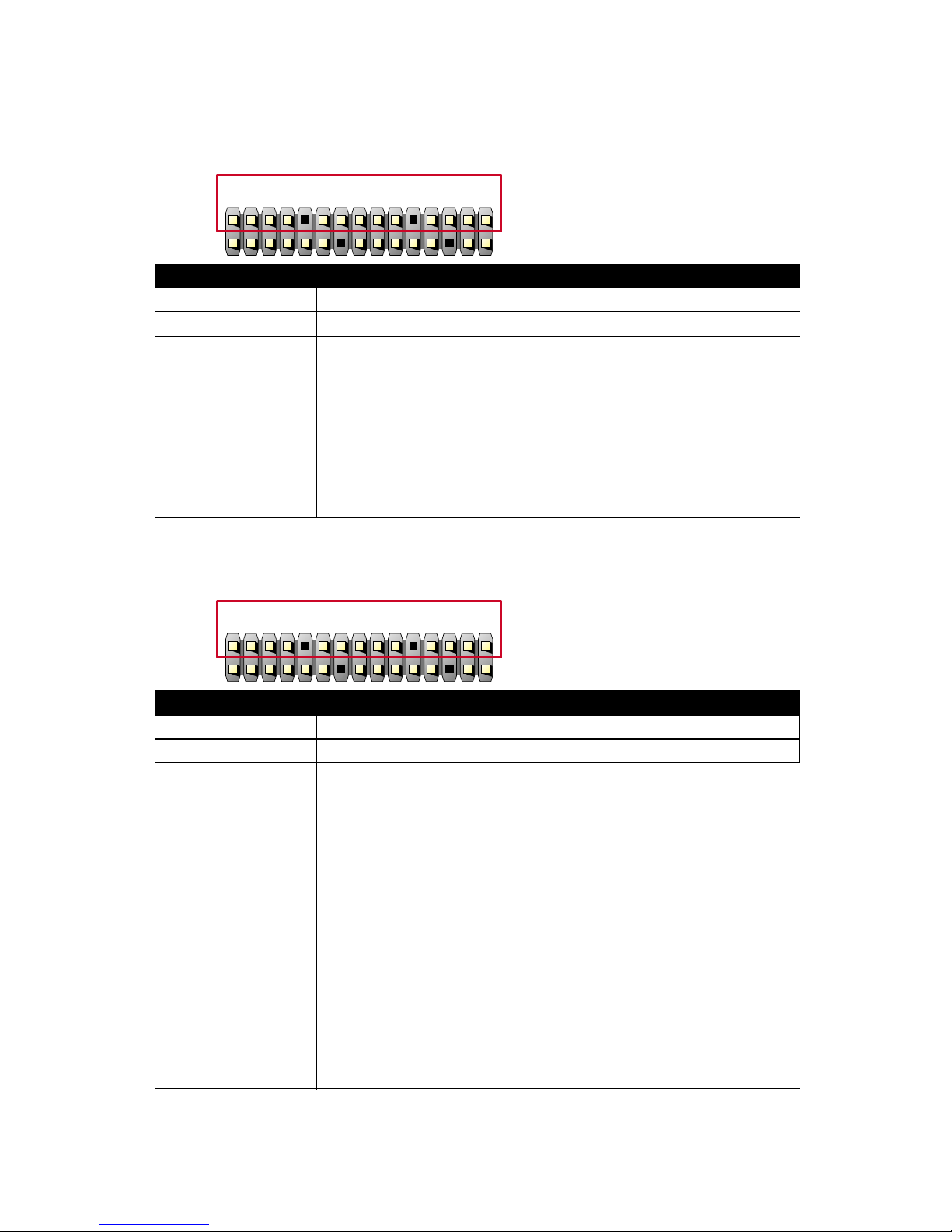
2-5.1 J1 SWITCH SIGNAL SUMMARY
123456789101112131415
J2
J1
PIN 1 +5V
HDD LED CONNECTOR
PIN 2 HDD LED SIGNAL
PIN 3 HDD LED SIGNAL
PIN 4 +5V
DESCRIPTION
This connector supplies power to the cabinet's IDE
activity LED. Read and write activity by devices
connected to the Primary or SecondaryIDE
connector will cause the LED to light up.
1234567891011 12 13 14 15
J2
J1
INFRARED CONNECTOR
PIN 6 INFRARED TRANSMIT SIGNAL
PIN 7 GND
PIN 8 INFRARED RECEIVE SIGNAL
PIN 9 NONE
PIN 10 +5V
DESCRIPTION
This connector supports an optional wireless
transmitting and receiving infrared module. This
module mounts to a small opening on system cases
that support this feature.
User must also configure the setting through
BIOS program "Peripheral Setup" to select whether
UART2 is directed for use with COM2 or IrDA.
Use the five pins and connect a ribbon cable from
the module to the motherboard's IR connector
according to the pin definitions.
MAGIC-PRO MP-6VIP-C2
17
ATX POWER SWITCH
PIN 12 ATX POWER SWITCH
PIN 13 GND
DESCRIPTION
The system power is controlled by a momentary
switch connected to this lead.
Pressing the button once will switch the system
between ON and SOFT OFF.
Pushing the switch while in the ON mode for more
4 seconds will turn the system off.
The system power LED shows the status of the
system's power.
123456789101112 13 14 15
J2
J1
SMI CONNECTOR
PIN 14 SMI(System Managment Interrupt) SIGNAL
PIN 15 GND
DESCRIPTION
This allows user to manually place the system into a
suspend mode or "Green" mode, where system
activity is decreased to save electricity and prolong
the life of certain components when the system is
not in use. This 2-oin connector connects to the
case-mounted suspend switch. If you do not have a
switch for the connector, you may use the "Turbo
Switch".
SMI is activated when it detects a short to open
moment and therefore leaving it shorted will not
cause any problems. This may require one or two
presses depending on the position of the switch.
Wake-Up can be controlled by settings in the BIOS
but the keyboard will always allow wake-up(the SMI
lead cannot wake up the system).
1234567891011121314 15
J2
J1

MAGIC-PRO MP-6VIP-C2
18
2-5.2 J2 SWITCH SIGNAL SUMMARY
123456789101112131415
J1
J2
PIN 1 SPEAKER SIGNAL
SPEAKER CONNECTOR
PIN 2 NONE
PIN 3 GND
PIN 4 +5V
DESCRIPTION
This SPEAKER connector connects to the casemounted speaker. Two sources (LINE OUT and
SPEAKER) allow you to hear system beeps and
warnings. Only SPEAKER allows you to hear system
beeps before the integrated audio has been properly
initialized.
1234567 8 9 10 11 12 13 14 15
J1
J2
PIN 5 RESET SIGNAL
RESET SWITCH CONNECTOR
PIN 6 GND
DESCRIPTION
RESET SWITCH connector connects to the casemounted reset switch for rebooting your system
without having to turn off your power switch. This is
a preferred method of reboot to prolong the life of
the system's power supply.
1234567891011 12 13 14 15
J1
J2
PIN 8 +5V
POWER LED CONNECTOR
PIN 9 NONE
PIN 10 GND
DESCRIPTION
This Power LED connector connects the system
power LED, which lights when the system is
powered on and blinks when it is in sleep mode.

MAGIC-PRO MP-6VIP-C2
19
1234567891011121314 15
J1
J2
PIN 14 SUSPEND LED SIGNAL
SUSPEND LED
PIN 15 GND
DESCRIPTION Connect to Suspend indicator light.

MAGIC-PRO MP-6VIP-C2
20
2-5.4 PS/2 MOUSE AND PS/2 KEYBOARD
PIN 6 : None
PIN 5 : Mouse Clock
PIN 4 : Vcc
PIN 3 : GND
PIN 2 : None
PIN 1 : Mouse Data
PS/2 MOUSE
PIN 6 : None
PIN 5 : Keyboard Clock
PIN 4 : Vcc
PIN 3 : GND
PIN 2 : None
PIN 1 : Keyboard Data
PS/2 KEYBOARD
2-5.3 ATX POWER SUPPLY CONNECTOR
• This connector connects to an ATX power supply. The plug from the power
supply only inserts in an orientation because of the different hole sizes.
Find the proper orientation and push down firmly making sure that all pins
are aligned.
• Reminding that your power supply should support at least 10mA on the 5V
standby voltage. It may cause an difficulty to power on the system if the
power supply cant support the load.
• For Wake On LAN function, the power supply should support at least
720mA current.
+3.3 Volts
-12.0 Volts
GND
Power Supply On
GND
GND
GND
-5.0 Volts
+5.0 Volts
+5.0 Volts
+3.3 Volts
+3.3 Volts
GND
+5.0 Volts
GND
+5.0 Volts
GND
Power Good
+5.0V Standby
+12.0 Volts

MAGIC-PRO MP-6VIP-C2
21
2-5.5 IRQ DESCRIPTION
• Both ISA and PCI expansion cards may require IRQs. System IRQs are
available to cards installed in the ISA expansion bus first, then any remaining IRQs are available to PCI cards. Currently, there are two types of ISA
cards.
• The original ISA expansion card design, now referred to as “Legacy” ISA
card, requires that you configurate the card’s jumpers manually and then
install it in any available slot on the ISA bus. To see a map of your used and
free IRQs in Windows 98, the Control Panel in My Computer, contains a
System icon, which gives you a Device Manager tab. Double-Clicking on a
specific hardware device gives you a Resources tab which shows the Interrupt number and address. Double-Clicking Computers to see all the interrupts and addresses for your system. Make sure that no two devices use
the same IRQ or your computer will experience problems when those two
devices are in use at the same time.
IRQO 0O System TimerOO 1
IRQ Function Description Priority
IRQO 1O Keyboard ControllerO 2O
IRQO 2O Programmable InterruptO N/A
IRQO 3O Serial Port (COM 2)O 11
IRQO 4O Serial Port (COM 1)O 12
IRQO 5OO 13O
IRQO 6O Floppy Disk ControllerO 14
IRQO 7O Parallel Port (LPT1)O 15
IRQO 8O Real Time Clock (RTC)O 3
IRQO 9OO 4
IRQO 10OO 5O
IRQO 11OO 6O
IRQO 12O PS/2 Mouse PortO 7
IRQO 13O CoprocessorO 8
IRQO 14O Primary IDE ChannelO 9
IRQO 15O Secondary IDE ChannelO 10

MAGIC-PRO MP-6VIP-C2
22
2-6 VOICE DIAGNOSTIC FUNCTION --- MP-6VIP-C2
• The Voice Diagnostic Function user with indispensable assist on
troublieshooting while assembling your computer components. If there is
any conflict or other potential problem triggers a boot-up failure, this voice
controller chip will voice you relistically where the conflict/problem is, then
user can remove the malfunction quickly.
• This function mainly provides 4 languages and their contents as following
table:

MAGIC-PRO MP-6VIP-C2
23
Chapter 3: BIOS Setup
• This 693 Apollo Pro Plus motherboard comes with the AWARD BIOS from
AWARD Software Inc. Enter the Award BIOS program Main Menu by:
1. Turn on or reboot your system. After a series of diagnostic checks, the
following message will appear:
PRESS <DEL> TO ENTER SETUP
2. Press the <DEL> key and the main program screen will appear as follows.
3. Using the arrows on your keyboard, select an option, and press <Enter>.
Modify the system parameters to reflect the options installed in your system.
4. You may return to the Main Menu anytime by pressing <ESC>.
5. In the Main Menu, “SAVE AND EXIT SETUP” saves your changes and
reboots the system, and “EXIT WITHOUT SAVING” ignores your changes
and exits the program.
ROM PCI / ISA BIOS (2A6LGSNC)
CMOS SETUP UTILITY
AWARD SOFTWARE, INC .
STANDARD CMOS SETUP
BIOS FEATURES SETUP
CHIPSET FEATURES SETUP
POWER MANAGEMENT SETUP
PNP/PCI CONFIGURATION
LOAD SETUP DEFAULTS
CPU SPEED SETTING
INTEGRATED PERIPHERALS
SUPERVISOR PASSWORD
USER PASSWORD
IDE HDD AUT O DETECTION
SA VE & EXIT SETUP
EXIT WITHOUT SAVING
Esc: Quit
F10: Save & Exit Setup (Shift) F2 : Change Color
Time, Date, Hard Disk Type...
: Select Item

MAGIC-PRO MP-6VIP-C2
24
3-1 STANDARD CMOS SETUP
• Standard CMOS Setup allows you to record some basic system hardware
configuration and set the system clock and error handling. You only need
to modify the configuration values of this option when you change your
system hardware configuration or the configuration stored in the CMOS
memory gets lost or damaged.
Run the STANDARD CMOS SETUP as following:
1. Choose “STAND CMOS SETUP” from the Main Menu and a screen with a
list of option will appear:
2. Use one of the arrow keys to move between options and modify the se-
lected options by using PgUp / PgDn / + / - keys.
ROM PCI / ISA BIOS
STANDARD CMOS SETUP
AWARD SOFTWARE, INC .
Date (mm:dd:yy) :Tue, Oct 19 1999
Time (hh:mm:ss) :15:15 : 20
HARD DISKS TYPESIZECYLS HEADPRECOMPLANDZSECTORMODE
Primary Master : Auto 0M 0 0 0 0 0AUTO
Primary Slave : Auto 0M 0 0 0 0 0AUTO
Secondary Master : Auto 0M 0 0 0 0 0AUTO
Secondary Slave : A uto 0M 0 0 0 0 0AUTO
Drive A:1.44, 3.5 in
Drive B:None
Video :EGA / VGA
Halt On:All Errors
Base Memory : 640K
Extended Memory : 64512K
Other Memory : 384K
Total Memory : 65536K
PU/PD/+/- : ModifyEsx : Quit
F10: Save & Exit Setup (Shift) F2 : Change Color
: Select Item

MAGIC-PRO MP-6VIP-C2
25
Date (mm:dd:yy)
Time (hh:mm:ss)
Set the current date and time.
Primary / Secondary
Master / Slave
This field records the specifications for all non-SCSI
hard disk drives installed in your system. Refer to the
respective documentation on how to install the drives.
Drive A / Drive B Set this field to the type(s) of floppy disk drive(s) in-
stalled in your system. The choices are:
360KB, 5.25in.,
1.2MB, 5.25in.,
720KB, 3.5in.,
1.44MB, 3.5in., (default)
2.88MB, 3.5in.,
None.
Video Set this field to the type of video display card installed
in the system. The choices are:
Monochrome,
Color 40x25,
VGA / EGA, (default)
Color 80x25.
Halt On Set this warning feature for the type of errors that will
cause the system to halt. The choices are:
No Errors,
All, But Keyboard,
All, But Diskette,
All, But Disk / Key.
3. Press <ESC> to return to the Main Menu when you finish setting up all
items.

MAGIC-PRO MP-6VIP-C2
26
3-2 BIOS FEATURES SETUP
• BIOS FEATURES SETUP allows you to improve your system performance
or set up sysem features according to your preference.
Run the BIOS FEATURES SETUP as following:
1. Choose “BIOS FEATURES SETUP” from the Main Menu and a screen
with a list of option will appear:
2. Use one of the arrow keys to move between options and modify the se-
lected options by using PgUp / PgDn / + / - keys. An explanation of the
<F> keys follows:
<F1>: “Help” gives oions available for each item.
<Shift> + <F2>: Change color.
<F5>: Get the previous values. These values are the values with which the
user started in the current session.
<F6>: Load all options with the BIOS default values.
<F7>: Load all options with the Setup default values.
Video BIOS Shadow O : Enabled
C8000-CBFFF Shadow O: Disabled
CC000-CFFFF Shadow O: Disabled
D0000-D3FFF Shadow O: Disabled
D4000-D7FFF Shadow O: Disabled
D8000-DBFFF Shadow O: Disabled
DC000-DFFFF Shadow O: Disabled
Virus W arningO : DisabledO
CPU Internal CacheO : Enab ledO
External CacheO : Enab ledO
CPU L2 Cache ECC CheckingO : EnabledO
Quick P ow er On Self TestO : EnabledO
BOot SequenceO : A, C , SCSIO
Swap Floppy DriveO : Disab ledO
Boot Up Floppy SeekO : DisabledO
Boot Up NumLock StatusO : OnO
IDE HDD Block ModeO : Enab ledO
Gate A20 OptionO : FastO
Memory Parity / ECC CheckO : Disab ledO
Typematic Rate SettingO : Disab ledO
Typematic Rate (Chars / Sec)O : 6O
Typematic Delay (Msec)O : 250O
Security OptionO : SetupO
PCI / V GA Palette SnoopO : DisabledO
OS Select for DRAMs > 64MBO : Non-OS/2O
Report No FDD For WIN95O : NoO
EscO : QuitO
F1O : HelpO
F5O : Old ValueO
F7O : Load Setup DefaultsO
PU/PD/+/- : ModifyO
(Shift) F2 : ColorO
: Select ItemO
ROM PCI/ISA BIOSO
BIOS FEATURES SETUPO
AWARD SOFTWARE, INC.O

MAGIC-PRO MP-6VIP-C2
27
CPU Internal Cache Choose Enabled (default) or Disabled. This option
allows you to enable or disable the CPU’s internal
cache.
External Cache Choose Enabled (default) or Disabled. This option
allows you to enable or disable the external cache.
Quick Power On Self
Test
Choose Enabled (default) or Disabled. This option
allows you to speed up the Power-On Self-Test
routine.
Boot Sequence Default is “A, C, SCSI”. This option determines which
drive to boot at first for an operating system.
Swap Floppy Drive Choose Enabled or Disabled (default). This option
swaps floppy drive assignments when it is enabled.
Boot Up Floppy Seek Enabled (default): During POST, BIOS checks the
track number of the floppy disk drive to see
whether it is 40 or 80 tracks.
Disabled: During POST, BIOS will not check the track
number of the floppy disk drive.
Boot Up NumLock
Status
Choose ON (default) or OFF. THis option lets user
activates the NumLock function at boot-up.
Virus Warning Enabled: Activates automatically when the system
boots up causing a warning message to
appear if there is anything attempting to
access the boot sector or hard disk partition table.
Disabled: No warning message will appear when there
is something attempting to access the boot
sector or hard disk partition table.
NOTE: Many diagnostic (or boot manager) programs which at-
tempt to access the boot sector table can cause the above
warning message. If you will be running such a program,
we recommend that you disable the virus protection first.

MAGIC-PRO MP-6VIP-C2
28
Gate A20 Option Choose Normal or Fast (default). This option allows
the RAM to access the memory above 1MB by using
the fast gate A20 line.
Memory Parity /
ECC Check
Choose Enabled or Disabled.
Typematic Rate Setting Choose Enabled or Disabled (default). Enable this
option to adjust the keystroke repeat rate.
Typematic Rate (Chars
/ Sec)
Range between 6 (default) and 30 characters per
second. This option controls the speed of repeating
keystrokes.
Typematic Delay
(Msec)
Choose 250 (default), 500, 750 and 1000. This option sets the time interval for displaying the first and
the second characters.
Security Option Choose System or Setup (default). This option pre-
vents unauthorized system boot-up or use of BIOS
setup.
PCI / VGA Palette
Snoop
Choose Enabled or Disabled (default). It determines
whether or not the MPEG ISA cards can work with
PCI / VGA.
OS Select For DRAM >
64MB
Non-OS/2 (default): For Non-OS/2 system.
OS: For OS/2 operating system.
IDE HDD Block Mode Choose Enabled (default) or Disabled. If your hard
disk size is larger than 540MB, then choose Enabled.
If you are using the IDE HDD AUTO DETECTION
option, the BIOS will choose this option automatically.
NOTE: Some older model HDDs do not provide this feature.

MAGIC-PRO MP-6VIP-C2
29
Report No FDD For
WIN95
Yes : BIOS reports “NO FDD” to Win95.
No (default): BIOS will not report “NO FDD” to Win95.
Video BIOS Shadow Enabled copies Video BIOS to shadow RAM for im-
proving performance.
The choice: Enabled (default), Disabled.
C8000-CBFFF to
DC000-DFFFF Shadow
These options are used to shadow other expansion
card ROMs.
3. Press <ESC> to return to the Main Menu when you finish setting up all
items.

MAGIC-PRO MP-6VIP-C2
30
3-3 CHIPSET FEATURES SETUP
• CHIPSET FEATURES SETUP allows you to change the values of chipset
registers. These registers control the system options.
Run the CHIPSET FEATURES SETUP as following:
1. Choose “CHIPSET FEATURES SETUP” from the Main Menu and a screen
with a list of option will appear:
2. Use one of the arrow keys to move between options and modify the se-
lected options by using PgUp / PgDn / + / - keys. An explanation of the
<F> keys follows:
<F1>: “Help” gives oions available for each item.
<Shift> + <F2>: Change color.
<F5>: Get the previous values. These values are the values with which the
user started in the current session.
<F6>: Load all options with the BIOS default values.
<F7>: Load all options with the Setup default values.
ROM PCI/ISA BIOSO
CHIPSET FEATURES SETUPO
AWARD SOFTWARE, INC.
Bank 0/1 DRAM Timing O: SDRAM 10ns
Bank 2/3 DRAM Timing O: SDRAM 10ns
Bank 4/5 DRAM Timing O: SDRAM 10ns
SDRAM Cycle Length O : 3
DRAM Clock O : Host CLK
Memory Hole O : Disabled
Read Around W rite O : Enabled
Concurrent PCI/Host O : Disabled
System BIOS Cacheable O: Disabled
Video RAM Cacheable O: Disabled
AGP Aperture Size O : 64M
AGP-2X Mode O : Disabled
OnChip USB O : Enabled
USB Keyboard Support O: Disabled
EscO : QuitO
F1O : HelpO
F5O : Old ValueO
F7O : Load Setup Defaults
PU/PD/+/- : ModifyO
(Shift) F2 : Color
: Select Item

MAGIC-PRO MP-6VIP-C2
31
Bank 0/1 2/3 4/5 DRAM
Timing
This item allows you to select the value in this field,
depending on whether the board has paged DRAMs
or EDO (Extended Data Output) DRAMs.
The choice: EDO 50ns,
EDO 60ns,
Slow,
Medium,
Fast,
Turbo.
SDRAM Cycle Length
TIme
You can select CAS latency time in HCLKs of 2/2 or
3/3. The system board designer should have set the
values in this field, depending on the DRAM installed.
Do not change the values in this field unless you
change specifications of the installed DRAM or the
installed CPU.
Read Around Write DRAM optimization feature: If a memory read is ad-
dressed to a location whose latest write isw being
held in a buffer before being written to memory, the
read is satisfied through the buffer contents, and the
read is not sent to the DRAM.
The choice: Enabled, Disabled.
Concurrent PCI / HOST When disabled, CPU bus will be occupied during the
entire PCI operation period.
The choice: Enabled, Disabled.
System BIOS
Cacheable
Choose Enabled or Disabled (default). When enabled,
the access to the system BIOS ROM addressed at
F0000H - FFFFFH is cached.
Video RAM Cacheable Choose Enabled or Disabled (default). When enabled,
the access to the VGA RAM addressed is cached.
AGP Aperture Size
(MB)
Choose 4, 8, 16, 32, 64 (default), 128 or 256 MB.
Memory mapped and graphics data structures can
reside in a Graphics Aperture. This area is like a linear buffer. BIOS will automatically report the starting
address of this buffer to the O.S.

MAGIC-PRO MP-6VIP-C2
32
AGP-2X Mode This item allows you to enable / disable the AGP-2X
(Clock 133MHz) mode.
OnChip USB This should be enabled if our system has a USB in-
stalled on the system board and you wish to use it.
Even when so wquipped, if you add a higher performance controller, you will need to disable this feature.
The choice: Enabled, Disabled.
USB Keyboard
Support
Enabled: Enable function when the USB keyboard is
being used.
Disabled (default): When the AT keyboard is being
used, choose disabled.
3. Press <ESC> to return to the Main Menu when you finish setting up all
items.

MAGIC-PRO MP-6VIP-C2
33
3-4 POWER MANAGEMENT SETUP
ROM PCI/ISA BIOSO
POWER MANAGEMENT SETUPO
AWARD SOFTWARE, INC.O
ACPI function O : Disabled
Power Management O : User Define
PM Control by APM O : Yes
Video Off After O : Suspend
Video Off Method O : V/H SYNC+Blank
MODEM Use IRQ O : 3
Soft-Off by PWRBTN O : Instant-Of f
HDD Power Down O : Disabled
Doze Mode O : Disabled
Suspend Mode O : Disabled
** PM Events **
VGA O : OFF
LPT & COM O : LPT/COM
HDD & FDD O : ON
DMA/MasterO : OFF
Modem Ring Resume O : Disabled
RTC Alarm Resume O : Enabled
Date (of Month)O : 0
Timer (hh:mm:ss)O : 0: 0: 0
Primary INTR O : ON
IRQ3 (COM 2) O : Primary
IRQ4 (COM 1) O : Primary
IRQ5 (LPT 2) O : Primary
IRQ6 (Floppy Disk) O : Primary
IRQ7 (L TP 1) O : Primary
IRQ8 (RTC Alarm) O : Disabled
IRQ9 (IRQ2 Redir) O : Secondary
IRQ10 (Reserved) O : Secondary
IRQ1 1 (Reserved) O : Secondary
IRQ12 (PS/2 Mouse) O: Primary
IRQ13 (Coprpcessor)O : Primary
IRQ14 (Hard Disk) O : Primary
IRQ15 (Reserved) O : Disabled
EscO : QuitO
F1O : HelpO
F5O : Old ValueO
F7O : Load Setup DefaultsO
PU/PD/+/- : ModifyO
(Shift) F2 : ColorO
: Select ItemO
• POWER MANAGEMENT SETUP allows you to set the system’s power
saving functions.
Run the POWER MANAGEMENT SETUP as following:
1. Choose “POWER MANAGEMENT SETUP” from the Main Menu and a
screen with a list of option will appear:
2. Use one of the arrow keys to move between options and modify the se-
lected options by using PgUp / PgDn / + / - keys. An explanation of the
<F> keys follows:
<F1>: “Help” gives oions available for each item.
<Shift> + <F2>: Change color.
<F5>: Get the previous values. These values are the values with which the
user started in the current session.
<F6>: Load all options with the BIOS default values.
<F7>: Load all options with the Setup default values.

MAGIC-PRO MP-6VIP-C2
34
ACPI Function Enabled: Turn on ACPI function.
Disabled (default): Turn off ACPI function.
Power Management Choose Max. Saving, User Define (default), Disabled
or Min. Saving.
PM Control by APM When enabled, an Advanced Power Management
device will be activated to enhance the Max. Power
Saving mode and stop the CPU internal clock, If Advanced Power Management (APM) is installed on your
system, selecting Yes gives better power savings. If
the Max. Saving is not enabled, this will be present to
No.
Video Off After Choose NA, Suspend, Standby (default), or Doze.
MODEM Use IRQ This determines the IRQ in which the MODEM can
use.
The choice: 3, 4, 5, 7, 9, 10, 11, NA.
Soft-Off by PWR-BTTN Instant-Off (default): Turn of f the system poer at once
after pushing the power button.
Delay 4 Sec: Turn off the system power 4 seconds
after pushing the power button. (to meet PC97/98
spec)
Doze Mode This mode sets the CPU speed down to 33MHz.
knalB+CNYSH/V
lacitrevehtffonrutotmetsysehtesuaclliwnoitcelessihT
ehtotsknalbetirwdnastropnoitazinorhcnyslatnozirohdna
.reffuboediv
neercSknalB .reffuboedivehtotsknalbsetirwylnonoitposihT
SMPD
rewoPyalpsiDehtstroppusrotinomruoyfinoitposihttceleS
oediVehtfodradnats)SMPD(gnilangiStnemeganaM
tnemeganamrewopoedivtcelesotsdradnatSscinortcelE
.seulav
Video Off Method This determines the manner in which the monitor is
blanked.

MAGIC-PRO MP-6VIP-C2
35
Standby Mode /
Suspend Mode
These two options allow you to choose the mode for
the different timers. The Standby Mode turns off the
VGA monitor, and the Suspend Mode turns off the
CPU and saves the energy of the system.
HDD Power Down Time is adjustable from 1 to 15 minutes. When the
set time has elapsed, the BIOS sends a command to
the HDD to power down, which turns off the motor.
Modem Ring Resume An input signal on the serial Ring Indicator (RI) Line
(in other words, an incoming call on the modem) Awakens the system from a soft off state.
RTC Alarm Resume When Enabled, you can set the data and time at the
which the RTC (Real Time Clock) alarm awakens the
system from suspend mode.
The choice: Disabled (default), Enabled.
Date (of Month) Set a certain date when RTC Alarm Resume option
is Enabled to awaken the system. THis option is concurrent with Resume TIme option.
Time (hh:mm:ss) Set a certain time when R TC Alarm Resume option is
Enabled to awaken the system. THis option is concurrent with Date option.
Primary INTR When set to On, any event occurring at will awaken a
system which has been powered down.
On (default): The system can not enter the power
saving mode when I/O ports or IRQ#
is activated.
Off: The system can enter the power saving mode
when I/O ports or IRQ# is activated.

MAGIC-PRO MP-6VIP-C2
36
The following is a list of IRQ’s (Interrupt ReQuests), which can be exempted
much as the COM ports and LPT ports above can. When an I/O device
wants to gain the attention of the operating system, it signals this by causing
an IRQ to occur. When the operating system is ready to respond to the
request, it interrupts itself and performs the service. When set On, activity
will neither prevent the system from going into a power management mode
nor awaken it.
IRQ 3 (COM 2)
IRQ 4 (COM 1)
IRQ 5 (LPT 2)
IRQ 6 (Floppy Disk)
IRQ 7 (LPT 1)
IRQ 8 (RTC Alarm)
3. Press <ESC> to return to the Main Menu when you finish setting up all
items.

MAGIC-PRO MP-6VIP-C2
37
3-5 PNP / PCI CONFIGURATION SETUP
ROM PCI/ISA BIOS
PNP/PCI CONFIGURATION
AWARD SOFTWARE, INC.
PNP OS Installed O : No
Resources Controlled By O: Auto
Reset Configuration Data O: Disabled
IRQ-3 assigned toO : PCI/ISA PnP
IRQ-4 assigned toO : PCI/ISA PnP
IRQ-5 assigned toO : PCI/ISA PnP
IRQ-7 assigned toO : PCI/ISA PnP
IRQ-9 assigned toO : PCI/ISA PnP
IRQ-10 assigned toO : PCI/ISA PnP
IRQ-1 1 assigned toO : PCI/ISA PnP
IRQ-12 assigned toO : PCI/ISA PnP
IRQ-14 assigned toO : PCI/ISA PnP
IRQ-15 assigned toO : PCI/ISA PnP
DMA-0 assigned toO : PCI/ISA PnP
DMA-1 assigned toO : PCI/ISA PnP
DMA-3 assigned toO : PCI/ISA PnP
DMA-5 assigned toO : PCI/ISA PnP
DMA-6 assigned toO : PCI/ISA PnP
DMA-7 assigned toO : PCI/ISA PnP
CPU to PCI Write BufferO : Enabled
PCI Dynamic Bursting O : Enabled
PCI Master 0 WS Write O : Enabled
PCI Delay Transaction O : Enabled
PCI#2 Access #1 Retry O : Disabled
AGP Master 1 WS Write O: Disabled
AGP Master 1 WS Read O: Disabled
PCI IRQ Actived ByO : Level
Assign IRQ For USB O : Enabled
Assign IRQ For VGA O : Enabled
EscO : QuitO
F1O : HelpO
F5O : Old ValueO
F7O : Load Setup DefaultsO
PU/PD/+/- : ModifyO
(Shift) F2 : ColorO
: Select ItemO
• PNP/PCI CONFIGURATION SETUP allows you to set the system’s power
saving functions.
Run the PNP/PCI CONFIGURATION SETUP as following:
1. Choose “PNP/PCI CONFIGURATION SETUP” from the Main Menu and a
screen with a list of option will appear:
2. Use one of the arrow keys to move between options and modify the se-
lected options by using PgUp / PgDn / + / - keys. An explanation of the
<F> keys follows:
<F1>: “Help” gives oions available for each item.
<Shift> + <F2>: Change color.
<F5>: Get the previous values. These values are the values with which the
user started in the current session.
<F6>: Load all options with the BIOS default values.
<F7>: Load all options with the Setup default values.

MAGIC-PRO MP-6VIP-C2
38
Resource Controlled
By
Choose Manual (default) or Auto. The BIOS checks
the IRQ / DMA channel number on the ISA and PCI
card manually if you choose Manual and the IRQ /
DMA channel number will be checked automatically
if you choose Auto.
Reset Configuration
Data
Choose Enabled or Disabled (default). Disabled retains PnP configuration data in BIOS and Enabled
resets the PnP configuration data in BIOS.
IRQ-x assigned to /
DMA-x assigned to
Legacy ISA: Manually assigns IRQ / DMA to device.
PCI / ISA PnP: BIOS automatically assigns IRQ / DMA
to device.
PNP OS Installed Yes: OS supports Plug and Play function.
No (default): OS doesn’t support Plug and Play
function.
NOTE: BIOS will automatically disable all PnP resources except
the boot device card when you select Yes on Non-PnP
operating system.
Assign IRQ for USB Enabled (default): Add one IRQ to USB controller.
Disabled: Remove IRQ from USB controller. The system will have extra IRQ for other devices but the USB
controller will still not be disabled. (only IRQ was
removed)
Assign IRQ for VGA Enabled (default): Add one IRQ to VGA controller.
Disabled: Remove IRQ from USB controller. The system will have extra IRQ for other devices but the VGA
controller will still not be disabled. (only IRQ was
removed)
3. Press <ESC> to return to the Main Menu when you finish setting up all
items.

MAGIC-PRO MP-6VIP-C2
39
3-6 LOAD SETUP DEFAULTS
• LOAD SETUP DEFAULTS option loads the default system values to the
system configuration fields. If the CMOS is corrupted, the defaults are loaded
automatically.
Choose “LOAD SETUP DEFAULTS” and the following message will appear:
“ Load Setup Defaults (Y / N) ? N ”
To use the setup defaults, change the prompt to “Y” and press <Enter> key.

MAGIC-PRO MP-6VIP-C2
40
3-7 CPU SPEED SETTING
• CPU SPEED SETTING option allows you to get some informations inside
your system when it is working.
Run the CPU SPEED SETTING as following:
1. Choose “CPU SPEED SETTING” from the Main Menu and a screen with
a list of option will appear:
2. Use one of the arrow keys to move between options and modify the se-
lected options by using PgUp / PgDn / + / - keys. An explanation of the
<F> keys follows:
<F1>: “Help” gives oions available for each item.
<Shift> + <F2>: Change color.
<F5>: Get the previous values. These values are the values with which the
user started in the current session.
<F6>: Load all options with the BIOS default values.
<F7>: Load all options with the Setup default values.
ROM PCI/ISA BIOS
CPU SPEED SETUP
AWARD SOFTWARE, INC.
Auto Detect DIMM/PCI ClockO : Disabled
Spread SpectrumOO : Disabled
CPU Host Clock (CPU/PCI) O : Default
EscO : Quit
F1O : Help
F5O : Old Value
F7O : Load Setup Defaults
PU/PD/+/- : Modify
(Shift) F2 : Color
: Select Item

MAGIC-PRO MP-6VIP-C2
41
Auto Detect DIMM /
PCI Clock
Choose Disabled (default) or Enabled. The clock generator will turn of f the DIMM clock if this slot is empty.
3. Press <ESC> to return to the Main Menu when you finish setting up all
items.
Spread Spectrum Choose Disabled (default) or Enabled. This function
is designed to EMI test only.
CPU Host Clock (CPU /
PCI)
Select the CPU Host Clock.
The choice: default, 66/33MHz, 75/37MHz, 83/
41MHz, 124/31MHz, 133/33MHz, 140/35MHz, and
150/37MHz.

MAGIC-PRO MP-6VIP-C2
42
3-8 INTEGRATED PERIPHERALS
ROM PCI/ISA BIOS
INTEGRATED PERPHERALS
AWARD SOFTWARE, INC.
OnChip IDE Channel0 : Enabled
OnChip IDE Channel1 : Enabled
IDE Prefetch Mode : Enabled
Primary Master PIO : A uto
Primary Slave PIO : Auto
Secondary Master PIO : A uto
Secondary Slave PIO : A uto
Primary Master UDMA : A uto
Primary Slave UDMA : Auto
Secondary MasterUDMA : A uto
Secondary Slave UDMA : A uto
Init Display First : PCI Slot
KBC input clock : 8 MHz
Onboard FDC Controller : Enabled
Onboard Serial Port 1 : 3F8/IRQ4
Onboard Serial Port 2 : 2F8/IRQ3
UAR T Mode Select :
UAR T2 Duple x Mode : Half
RxD , TxD Activ e : Lo, Lo
IR Transmission delay : Disabled
Onboard Parallel Port : 378/IRQ7
Parallel Port Mode : ECP/EPP
ECP Mode Use DMA : 3
EPP Mode Select : EPP1.7
POWER ON Function :
KB Po wer ON P ass w ord: Enter
Hot Key Power On : Ctrl - F1
Esc: Quit
F1 : Help
F5 : Old Value
F7 : Load Setup Defaults
PU/PD/+/- : Modify
(Shift) F2 : Color
: Select Item
• INTEGRATED PERIPHERALS option allows you to get some informations
inside your system when it is working.
Run the INTEGRATED PERIPHERALS as following:
1. Choose “INTEGRA TED PERIPHERALS” from the Main Menu and a screen
with a list of option will appear:
2. Use one of the arrow keys to move between options and modify the se-
lected options by using PgUp / PgDn / + / - keys. An explanation of the
<F> keys follows:
<F1>: “Help” gives oions available for each item.
<Shift> + <F2>: Change color.
<F5>: Get the previous values. These values are the values with which the
user started in the current session.
<F6>: Load all options with the BIOS default values.
<F7>: Load all options with the Setup default values.

MAGIC-PRO MP-6VIP-C2
43
OnChip IDE Channel
0 / 1
The chipset contains a PCI IDE interface with support from two IDE channels. Select Enabled to activate the first and/or the second IDE interface. Select
Disabled to deactivate an interface if you install a primary and/or second add-on IDE interface.
The choice: Enabled (default), Disabled.
Primary
Master / Slave PIO
Secondary
Master / Slave PIO
Choose Auto (default) or Mode 0~4. The BIOS will
detect the HDD mode type automatically when you
choose Auto. You need to set to a lower mode than
Auto when your hard disk becomes unstable.
The choice: Auto, Mode 0, Mode 1, Mode 2, Mode 3,
Mode 4.
Primary
Master / Slave UDMA
Secondary
Master / Slave UDMA
Ultra DMA/66 implementation is possible only if your
IDE hard drive supports it and the operating environment includes a DMA drive and your system software
both support Ultra DMA/66, select Auto to enable
BIOS support.
The choice: Auto, Disabled.
IDE Prefetch Mode The onboard IDE drive interfaces supports IDE
prefetching for faster drive accesses. If you install a
primary and/or secondary add-in IDE interfaces, set
this field to Disabled if the interface does not support
prefetching.
The choice: Enabled, Disabled.
Init Display First This option allows you to decide to activate PCI Slot
or AGP first.
The choice: PCI Slot (default), AGP.
KBC input clock This item allows you to set up the I/O keyboard con-
troller for the clock frequency.
The choice: 6MHz, 8MHz, 12MHz, 16MHz.
Onboard FDC
Controller
Select Enabled if your system has a floppy drive controller (FDC) installed on the system board and you
want to use it. If you install add-in FDC or the system
has no floppy drive, select Disabled in this field.
The choice: Enabled, Disabled.

MAGIC-PRO MP-6VIP-C2
44
Onboard Serial
Port 1 / Port2
Select an address and corresponding interrupt for the
first and second serial ports.
The choice: 3F8/IRQ4, 2E8/IRQ3, 3E8/IRQ4, 2F8/
IRQ3, Disabled, Auto.
UART Mode Select This item allows you to select UART mode.
The choice: Enabled, Disabled.
UART2 Duplex Mode This item allows you to select the IR half / full duplex
function.
The choice: Half, Full.
RxD, TxD Active This item allows you to determine the active of RxD,
TxD.
The choice: “Hi, Hi”, “Hi, Lo”, “Lo, Lo”, “Lo, Hi”.
IR Transmission delay This item allows you to enable / disable IR transmis-
sion delay.
The choice: Enabled, Disabled.
Onboard Parallel Port This item allows you to determine onboard parallel
port controller I/O address setting.
The choice: 378H/IRQ7, 278H/IRQ5, 3BC/IRQ7,
Disabled.
Parallel Port Mode Select an operating mode for the onboard parallel
(printer) port. Select Normal, Compatible, or SPP
unless you are certain your hardware and software
both support one of the other available modes.
The choice: SPP, EPP, ECP, ECP + EPP.
ECP Mode Use DMA Select a DMA channel for the parallel port for use
during ECP mode.
The choice: 3, 1.
EPP Mode Select Select EPP port type 1.7 or 1.9
The choice: EPP1.7, 1.9.

MAGIC-PRO MP-6VIP-C2
45
KB Power ON
Password
When user sets a password for keyboard, the password that user set returns the system to Full On state.
Hot Key Power On Boot up the system via predetermined keyboard hot
key.
The choice: <Ctrl> + <F1>...<F12>.
3. Press <ESC> to return to the Main Menu when you finish setting up all
items.

MAGIC-PRO MP-6VIP-C2
46
3-9 SUPERVISOR / USER PASSWORD
• These two options allow you to set your sysem passwords. Normally, the
supervisor has a higher ability to change the CMOS setup option than the
user. The way to set up the passwords for both Supervisor and User are
as follows:
1. Choose “Change Password” in the Main Menu and press <Enter>. The
following message appears:
“Enter Password : “
2. The first time you run this option, enter your password up to 8 characters
and press <Enter>. The screen does not display the enterd characters.
3. After you enter the password, the following message appears prompting
you to confirm the password:
“Confirm Password : “
4. Enter the same password “exactly” as you just typed again to confirm the
password and press <Enter>.
5. Move the cursor to Save & Exit Setup to save the password.
6. If you need to delete the password ou entered before, choose the Super-
visor Password and press <Enter>. It will delete the password that you
had before.
7. Move the cursor to Save & Exit Setup to save the option you did, other-
wise the old password will still be there the next time you turn your system
on.
8. Press <Enter> to exit to the Main Menu.
NOTE: If you forget or lose the password, the only way to access
the system is to clear the CMOS RAM. All setup informations will be lost and you need to run the BIOS setup program again.

MAGIC-PRO MP-6VIP-C2
47
3-10 HDD AUTO DETECTION
• IDE HDD AUTO DETECTION option can automatically detect and find the
parameters of IDE Hard Drive. Meanwhile, the informations that BIOS detected will record to the STANDARD CMOS SETUP screen.
• The screen will request you to select a specific Hard Drive for Primary
Master after you select this option. If you accept a Hard Drive detected by
the BIOS, you can press “Y” to confirm and then press <Enter> to check
next Hard Drive. This function allows you to check four Hard Drives and
you may press <ESC> after the <Enter> to skip this function and go back to
the Main Menu.
3-11 SAVE & EXIT SETUP
• SAVE & EXIT SETUP allows you to save all modifications you have speci-
fied into the CMOS memory. Highlight this option on the Main Menu and
the following message appears:
“SAVE to CMOS and EXIT (Y/N) ? Y “
Press <Enter> key to save the configuration changes.
3-12 EXIT WITHOUT SAVING
• EXIT WITHOUT SAVING option allows you to exit the Setup Utility without
saving the modifications that you have specified. Highlight this option on
the Main Menu and the following message appears:
“Ouit Without Saving (Y/N) ? N “
You may change the prompt to “Y” and press <Enter> key to leave this option .
 Loading...