


Service
This manual is to be used by qualified appliance
technicians only. Maytag does not assume any
responsibility for property damage or personal
injury for improper service procedures done by
an unqualified person.
18 & 21
Cubic Foot
Top Mount
Refrigerators
This Base Manual covers general information
Refer to individual Technical Sheet
for information on specific models
This manual includes, but is
not limited to the following:
ATB1821AR*
ATB1830AR*
ATB1836AR*
ATB1838AE*
ATB1832AR*
ATB2130AR*
ATB2132AR*
ATB2136AR*
ATB2138AR*
ATF2136AR*
ATF2138AR*
CTB1821AR*
CTN1821AE*
CTL1821AE*
CTB2121AR*
CTF2126AR*
MTB1891AR*
MTB1893AR*
MTB1895AE*
MTB2193AR*
MTB2195AR*
MTF2193AR*
MTF2195AE*
16025860
Replaces 16023446
January 2005

!
!
!
!
Important Information
Important Notices for Servicers and Consumers
Maytag will not be responsible for personal injury or property damage from improper service procedures. Pride and
workmanship go into every product to provide our customers with quality products. It is possible, however , that
during its lifetime a product may require service. Products should be serviced only by a qualified service technician
who is familiar with the safety procedures required in the repair and who is equipped with the proper tools, parts,
testing instruments and the appropriate service information. IT IS THE TECHNICIANS RESPONSIBILITY TO
REVIEW ALL APPROPRIATE SERVICE INFORMATION BEFORE BEGINNING REPAIRS.
WARNING
To avoid risk of severe personal injury or death, disconnect power before working/servicing on appliance to avoid
electrical shock.
To locate an authorized servicer, please consult your telephone book or the dealer from whom you purchased this
product. For further assistance, please contact:
Customer Service Support Center
CAIR Center
Web Site Telephone Number
WWW.AMANA.COM ............................................... 1-800-843-0304
WWW.JENNAIR.COM ............................................ 1-800-536-6247
WWW.MAYTAG.COM............................................. 1-800-688-9900
CAIR Center in Canada..........................................1-800-688-2002
Amana Canada Product .... ....... ....... ........................ 1-866-587-2002
Recognize Safety Symbols, Words, and Labels
DANGER
DANGER—Immediate hazards which WILL result in severe personal injury or death.
WARNING
WARNING—Hazards or unsafe practices which COULD result in severe personal injury or death.
CAUTION
CAUTION—Hazards or unsafe practices which COULD result in minor personal injury, product or property
damage.
16025860 2 ©2005 Maytag Services

Table of Contents
Important Information ................................................. 2
Model Identification.................................................... 4
Component Testing
Compressor ............................................................ 5
Resistance Test .......................................................5
Ground Test............................................................. 5
Operation T est......................................................... 5
Capacitor................................................................. 6
Condenser...............................................................6
Overload / Relay...................................................... 7
Temperature Control ............................................... 7
Ice Maker ................................................................ 7
Condenser Motor.....................................................7
Evaporator Fan Motor ............................................. 7
Upper Freezer Light Switch .....................................8
Drier ........................................................................ 8
Defrost Timer .......................................................... 8
Evaporator............................................................... 9
Defrost Heater......................................................... 9
Defrost Thermostat ................................................. 9
Service Procedures
Service Equipment ................................................ 10
Drier Replacement ................................................ 10
Refrigerant Precautions............................................ 11
Line Piercing V alves .............................................. 11
Open Lines............................................................ 11
Compressor Operational Test................................ 11
Dehydrating Sealed Refrigeration System ............. 12
Leak Testing .......................................................... 12
Restrictions ...........................................................13
Evacuation and Charging ......................................... 14
Evacuation ............................................................ 14
Charging................................................................ 15
Refrigerant Charge ...................................................15
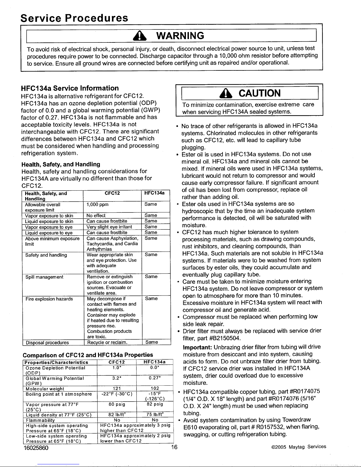
HFC134a Service Information .................................. 16
Health, Safety , and Handling ................................. 16
Comparison of CFC12 and HFC134a Properties .. 16
Replacement Service Compressor ..........................17
Compressor Testing Procedures ........................... 17
Refrigerant Flow ....................................................... 18
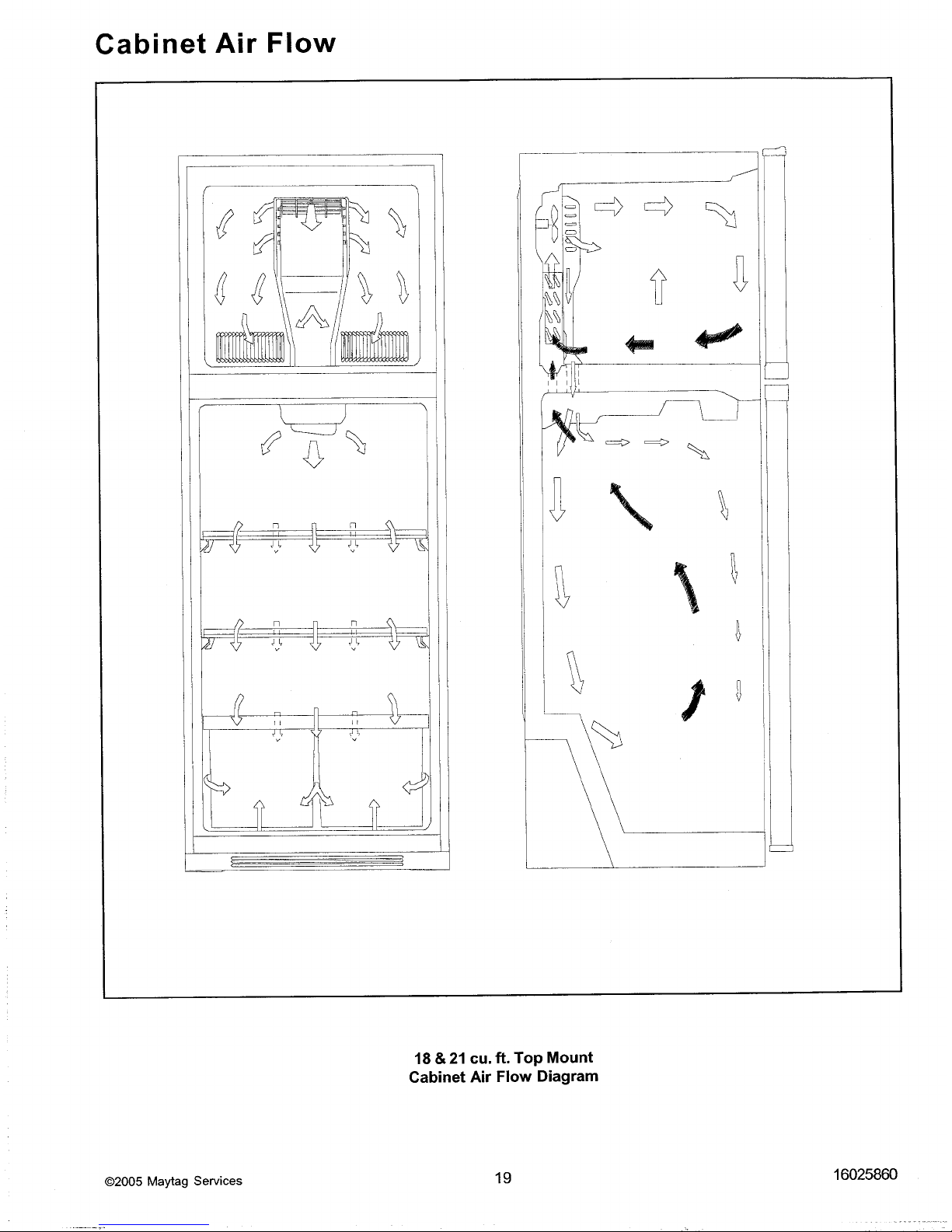
Cabinet Air Flow ....................................................... 19
Troubleshooting Chart .........................................20-22
System Diagnosis
Symptoms of an Overcharge................................. 23
Symptoms of Refrigeration Shortage.....................23
Symptoms of a Restriction .................................... 24
Symptoms of Air in System ................................... 24
Symptoms of Low or High Ambient ....................... 25
T emperature Installation........................................ 25
Heat Load..............................................................25
Disassembly Procedures
Door Removal
Freezer Door .........................................................26
Fresh Food Door ................................................... 26
Refrigerator Compartment
Light Bulb .............................................................. 27
Light Bulb Assembly.............................................. 27
Defrost Timer ........................................................ 27
Light Switch ...........................................................27
Cold Control .......................................................... 27
Freezer Compartment
Evaporator Cover .................................................. 27
Freezer T emperature Control ................................ 27
Evaporator Fan, Evaporator Motor ........................ 27
Defrost Terminator (Thermostat) ........................... 27
Defrost Heater....................................................... 27
Evaporator Removal.............................................. 28
Bottom of Cabinet
Front Roller Assembly ........................................... 28
Rear Roller Assembly............................................ 28
Condensate Drain Pan .......................................... 28
Machine Compartment
Condenser Fan & Fan Motor .................................28
Compressor .......................................................... 28
Overload/Relay/Capacitor......................................28
Condensate Drain Tube ........................................ 28
Condenser Removal.............................................. 28
Appendix A
Ice Maker Service Instructions ............................ A-2
Appendix B
Owners Manual ................................................... B-2
©2005 Maytag Services 3 16025860
Model Identification
Top Mount Refrigerator models vary in trim and
accessories, but all models have the same basic
construction. "Operating Instructions" and "Service
Instructions" apply to all cabinets unless stated
otherwise.
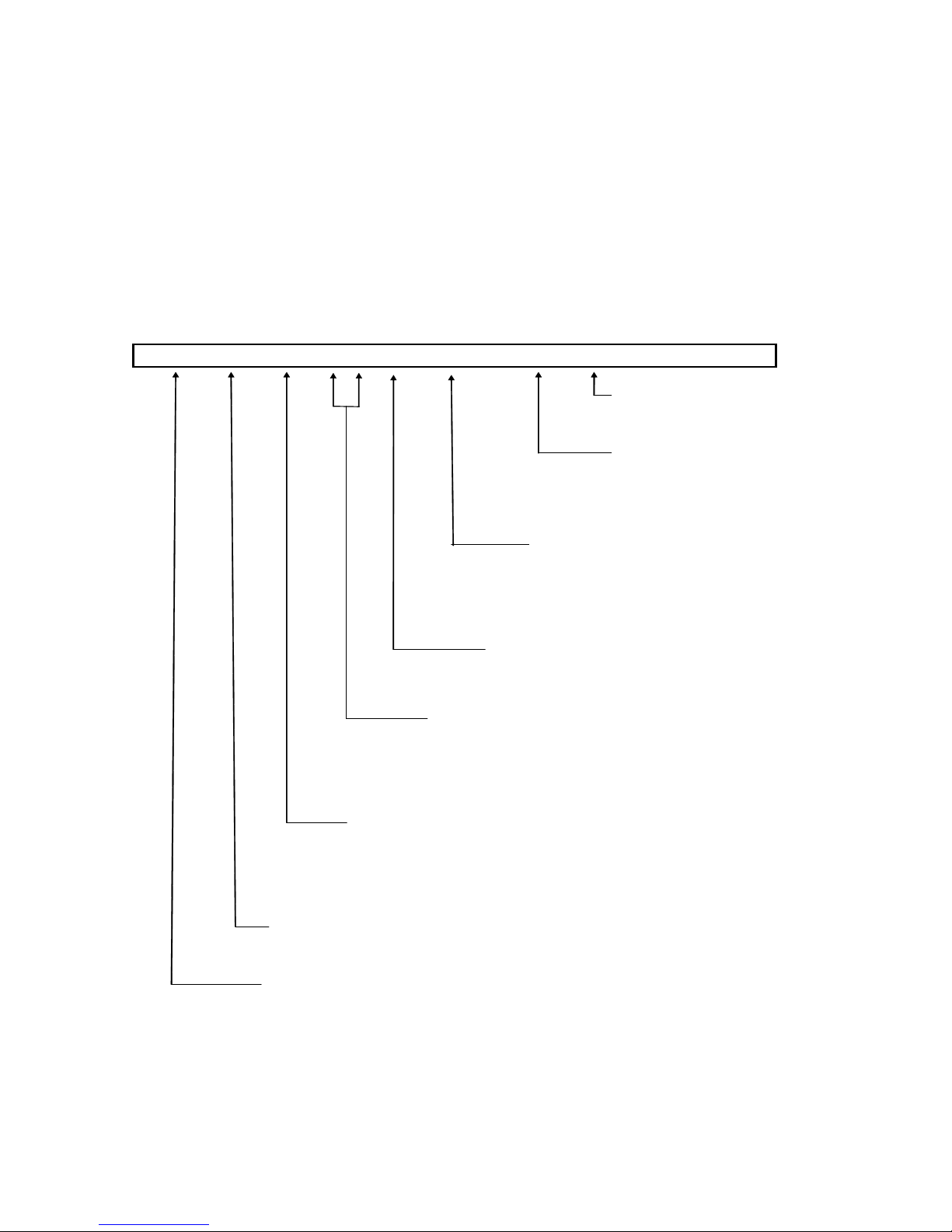
A T B 1 8 0 4 A R W
R = Regular
E = Energy Model
Brand
A = Amana
M = Maytag
` C = Magic Chef
Product
T ⎯ Top M ount
16025860 4 ©2005 Maytag Services
For positive identifications of individual units, state
complete serial number, model, and type. This
information is found on the serial plate located on front
upper right hand corner of foodliner or on some
models, exterior back of the outer casing.
An explanation of coding contained in Type position is
shown below.
Model Identification
Color
W ⎯ White
Q ⎯ B isque
Energy
Feature Package
1 - 3 ⎯ Good
4 - 6 ⎯ Better
7 ⎯ Best
Special Features
0 ⎯ Brand Base
Capacity
18 or 21 ⎯ C ubic Foot
Configuration
B ⎯ P rovisional
L ⎯ Left H and (Non P rovisional)
N ⎯ Right Hand(N on Provisional)
Component Testing
!
WARNING
To avoid risk of electrical shock, personal injury, or death, disconnect electrical power source to unit, unless test
procedures require power to be connected. Discharge capacitor through a resistor before attempting to service.
Ensure all ground wires are connected before certifying unit as repaired and/or operational.
Component Description Test Procedures
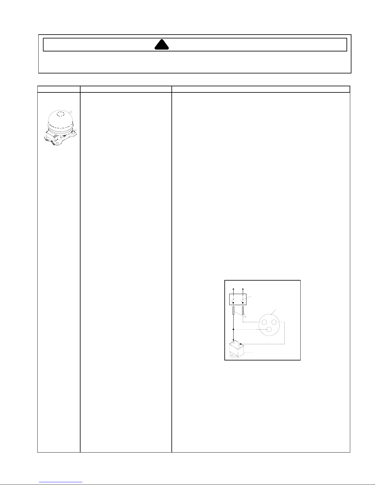
Compressor
When compressor electrical circuit is
energized, the start winding current
causes relay to heat. After an amount of
starting time, the start winding circuit
turns off. The relay will switch off the start
winding circuit even though compressor
has not started (for example, when
attempting to restart after momentary
power interruption).
With “open” relay, compressor will not
start because there is little or no current
to start windings. Overload protection will
open due to high locked rotor run winding
current.
With “shorted” relay or capacitor,
compressor will start and overload
protector will quickly open due to high
current of combined run and start
windings.
With open or weak capacitor,
compressor will start and run as normal
but will consume more energy.
Resistance test
1. Disconnect power to unit.
2. Discharge capacitor by shorting across terminals with a resistor for 1 minute.
NOTE: (Some compressors do not use a run capacitor.)
3. Remove leads from compressor terminals.
4. Set ohmmeter to lowest scale.
5. Check for resistance between
Terminals “S” and “C”, start winding
Terminals “R” and “C”, run winding
If either compressor winding reads open (infinite or very high resistance) or
dead short (0 ohms), replace compressor.
Ground test
1. Disconnect power to refrigerator.
2. Discharge capacitor, if present, by shorting terminals through a resistor.
3. Remove compressor leads and use an ohmmeter set on highest scale.
4. Touch one lead to compressor body (clean point of contact) and other probe
to each compressor terminal.
• If reading is obtained, compressor is grounded and must be replaced.
Operation test
If voltage, capacitor, overload, and motor winding tests do not show cause for
failure, perform the following test:
1. Disconnect power to refrigerator.
2. Discharge capacitor, if present, by shorting terminals through a resistor.
3. Remove leads from compressor terminals.
4. Wire a test cord to power switch.
5. Place time delayed fuse with UL rating equal to amp rating of motor in test
cord socket. (Refer to Technical Data Sheet)
6. Remove overload and relay.
7. Connect start, common and run leads of test cord on appropriate terminals of
compressor.
8. Attach capacitor leads of test cord together. If capacitor is used, attach
capacitor lead to a known good capacitor of same capacity.
To AC supply
Switch
Compressor
Fuses
CRS
Capacitor
Test configuration
9. Plug test cord into wattmeter to determine start and run wattage and use a
multimeter to check for low voltage, which can also be a cause of a
compressor not starting.
10. With power to multimeter, press start cord switch and release.
• If compressor motor starts and draws normal wattage, compressor is okay
and trouble is with either the capacitor, relay/overload, temperature
control, or elsewhere in system.
• If compressor does not start when direct wired, recover refrigerant at high
side. After refrigerant is recovered, repeat compressor direct wire test. If
compressor runs after recovery but would not run when direct wired
before recover, a restriction in sealed system is indicated.
• If compressor does not run when wired direct after recovery, replace faulty
compressor.
©2005 Maytag Services 16025860
5
Component Testing
!
WARNING
To avoid risk of electrical shock, personal injury, or death, disconnect electrical power source to unit, unless test
procedures require power to be connected. Discharge capacitor through a resistor before attempting to service.
Ensure all ground wires are connected before certifying unit as repaired and/or operational.
Component Description Test Procedures
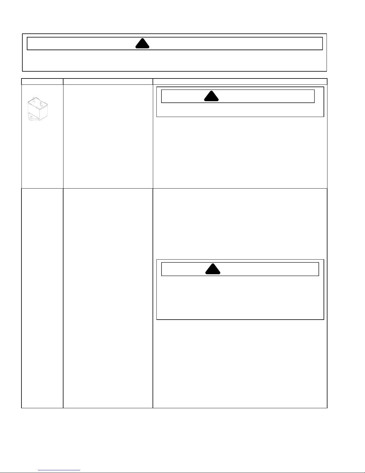
Capacitor
Condenser Condenser is a long folded tube
Run capacitor connects to relay terminal
3 and L side of line.
Some compressors do not require a run
capacitor; refer to the Technical Data
Sheet for the unit being serviced.
construction located in machine
compartment.
Condenser is on high pressure discharge
side of compressor. Condenser function
is to transfer heat absorbed by refrigerant
to ambient.
Higher pressure gas is circulated through
condenser where, as gas temperature is
reduced, It condenses into a high
pressure liquid state. Heat transfer takes
place because discharged gas is at a
higher temperature than air that is
passing over condenser. It is very
important that adequate air flow over
condenser is maintained.
Condenser is air cooled by condenser fan
motor. If efficiency of heat transfer from
condenser to surrounding air is impaired,
condensing temperature will increase.
High liquid temperature means liquid will
not remove as much heat during boiling
in evaporator as under normal conditions.
This would be indicated by high than
normal head pressures, long run time,
and high wattage. Remove any lint or
other accumulation, that would restrict
normal air movement through condenser.
From the condenser the refrigerant flows
into a post condenser loop which helps
control exterior condensation on flange,
center mullion, and around freezer door.
Refrigerant flows through the drier to the
capillary tube to the evaporator and back
to the compressor through suction line.
To avoid electrical shock which can cause severe personal injury or death,
discharge capacitor through a resistor before handling.
1. Disconnect power to refrigerator.
2. Disconnect the capacitor wires if present.
3. Discharge capacitor by shorting across terminals with a resistor for 1 minute.
4. Check resistance across capacitor terminals with ohmmeter set on “X1K”
scale.
• Good—needle swings to 0 ohms and slowly moves back to infinity.
• Open—needle does not move. Replace capacitor.
• Shorted—needle moves to zero and stays. Replace capacitor.
• High resistance leak—needle jumps toward 0 and then moves back to
constant high resistance (not infinity).
Leaks in condenser can usually be detected by using an electronic leak detector
or soap solution. Look for signs of compressor oil when checking for leaks that
may indicate the location of the leak. A certain amount of compressor oil is
circulated with refrigerant.
Leaks in post condenser loop are rare because loop is a one-piece steel tube.
“For small leaks”
1. Separate condenser from rest of refrigeration system and pressurize
condenser up to a maximum of 235 PSI with a refrigerant and dry nitrogen
combination.
2. Recheck for leaks.
To avoid severe personal injury or death from sudden eruption of high
pressures gases, observe the following:
Protect against a sudden eruption if high pressures are required for leak
checking.
Do not use high pressure compressed gases in refrigeration systems
without a reliable pressure regulator and pressure relief valve in the
lines.
WARNING
!
WARNING
!
16025860
6
©2005 Maytag Services

Component Testing
!
WARNING
To avoid risk of electrical shock, personal injury, or death, disconnect electrical power source to unit, unless test
procedures require power to be connected. Discharge capacitor through a resistor before attempting to service.
Ensure all ground wires are connected before certifying unit as repaired and/or operational.
Component Description Test Procedures
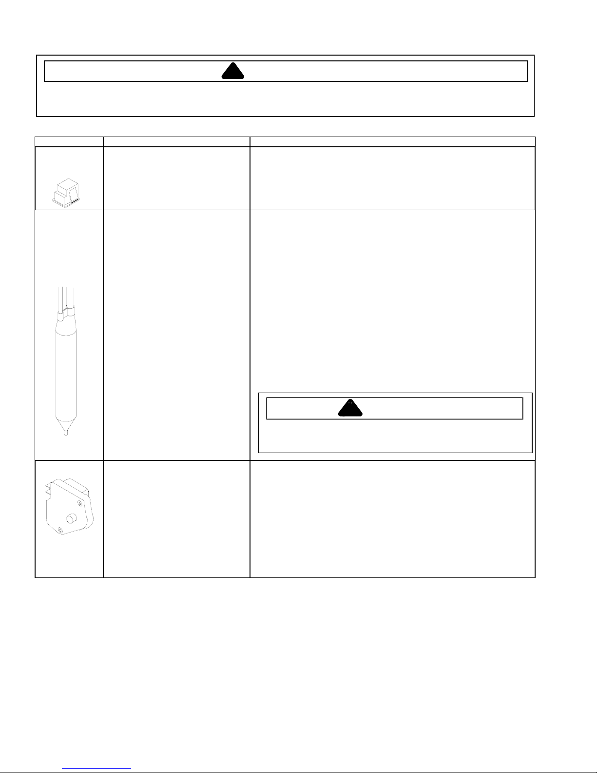
Overload / Relay
Temperature
control
Ice maker Optional on some models.
Condenser motor
Evaporator fan
motor
When voltage is connected and relay is
cool, current passes through relay to start
winding.
After a short time, current heats the
resistor in relay and resistance will raise
blocking current flow through relay.
Start winding remains in the circuit through
run capacitor.
Solid state relay plugs directly on
compressor start and run terminals. Relay
terminals 2 and 3 are connected within
relay. Run capacitor is connected to relay
terminal 3. L2 side of 120 VAC power is
connected to relay terminal 2.
Temperature control uses a capillary tube
to sense the temperature in the
compartment. Depending upon the
temperature it senses it will open or close
a single pole, single throw switch.
Temperature control controls run cycle
through defrost timer.
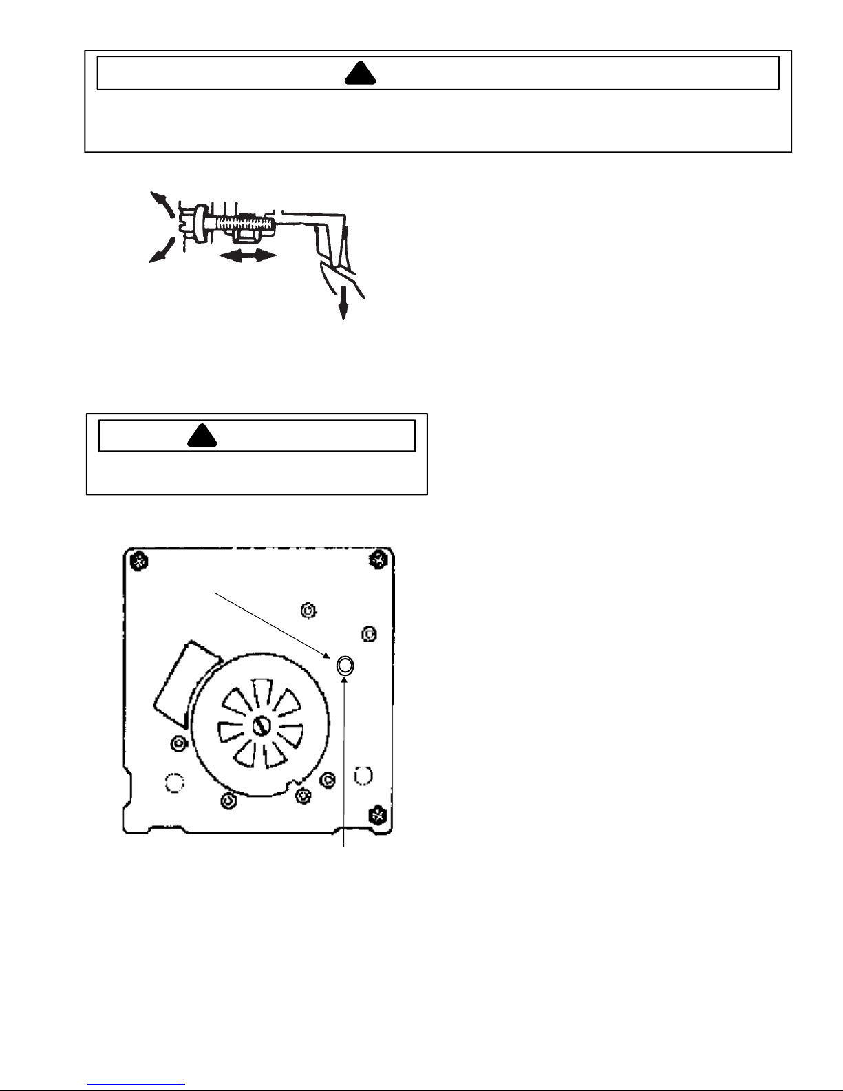
Altitude Adjustment
When altitude adjustment is required on a
G.E. control, turn altitude adjustment
screw 1/7 turn counter clockwise for each
1,000 feet increase in altitude up to 10,000
feet. One full turn equals 10,000 feet
maximum.
In most cases the need for altitude
adjustments can be avoided by simply
turning temperature control knob to colder
setting.
See “Ice Maker” section for service
information.
Condenser fan moves cooling air across
condenser coil and compressor body.
Condenser fan motor is in parallel circuit
with compressor.
Evaporator fan moves air across
evaporator coil and through the refrigerator
and freezer compartment.
1. Disconnect power to the refrigerator.
2. Remove relay cover and disconnect leads.
3. Check resistance across terminals 2 and 3 with an ohmmeter:
Normal = 3 to 12 ohms
Shorted = 0 ohms
Open = infinite ohms
Check for proper calibration with thermocouple capillary in air supply well by
recording cut-in and cut-out temperatures at middle setting. Refer to tech sheet
for model being serviced for expected temperatures.
Check control contacts are opening by disconnecting electrical leads to control
and turning control knob to coldest setting. Check for continuity across
terminals.
Altitude Counter in Feet
Feet Above
Sea Level
2,000
4,000
6,000
8,000
10,000
Check resistance across windings If open replace motor.
1. Disconnect power to unit.
2. Disconnect fan motor leads.
3. Check resistance from ground connection solder. Trace to motor frame must
not exceed .05 ohms.
4. Check for the proper operating voltage at the connector to motor with unit in
refrigeration mode and compressor operating.
Turn Screw
Clockwise (Angular
Degrees)
30
81
129
174
216
©2005 Maytag Services 16025860
7
Component Testing
!
WARNING
To avoid risk of electrical shock, personal injury, or death, disconnect electrical power source to unit, unless test
procedures require power to be connected. Discharge capacitor through a resistor before attempting to service.
Ensure all ground wires are connected before certifying unit as repaired and/or operational.
Component Description Test Procedures
Switch, upper
freezer light
Drier
Defrost timer Timer motor operates only when fresh
Single pole, single throw switch
completes circuit for light when door is
open.
Drier is placed at post condenser loop
outlet and passes liquefied refrigerant to
capillary.
Desiccant (20) 8 x 12 4AXH - 7 M>S> Grams
food control is closed.
After specified amount of actual
operating time, inner cam in timer throws
the contacts from terminal 4, compressor
circuit, to terminal 2, defrost
thermostat/defrost heater circuit.
After specified defrost cycle time, timer
cam resets the circuitry through terminal
4 to compressor.
Check resistant across terminals.
Switch arm depressed
“NO” terminals Open
Switch arm up
“NO” terminals Closed
Drier must be changed every time the system is opened for testing or
compressor replacement.
NOTE: Drier used in R12 sealed system is not interchangeable with
drier used in R134a sealed system.
Before opening refrigeration system, recover HFC134a refrigerant for safe
disposal.
1. Cut drier out of system using the following procedure. Do not unbraze
drier since this will drive moisture into the system.
2. Score capillary tube close to drier and break. Reform inlet tube to drier
allowing enough space for large tube cutter.
3. Cut circumference of drier 1 ¼" below condenser inlet tube joint to
drier.
4. Remove drier.
5. Apply heat trap paste on post condenser tubes to protect grommets
from high heat.
6. Unbraze remaining part of drier. Remove drier from system.
7. Discard drier in safe place. Do not leave drier with customer. If
refrigerator is under warranty, old drier must accompany warranty
1. To check timer motor winding, check for continuity between terminals 1 and 3
2. Depending on rotating position of the cam, terminal 1 of timer is common to
3. With continuity between terminals 1 and 4, rotate timer knob clockwise until
4. Continuing to rotate time knob until a second click is heard should restore
claim.
WARNING
!
To avoid death or severe personal injury, cut drier at correct location.
Cutting drier at incorrect location will allow desiccant beads to scatter. If
spilled, completely clean area of beads.
of timer.
both terminal 2, the defrost mode, and terminal 4, the compressor mode.
There should never be continuity between terminals 2 and 4.
audible click is heard. When the click is heard, reading between terminals 1
and 4 should be infinite and there should be continuity between terminals 1
and 2.
circuit between terminals 1 and 4.
16025860
8
©2005 Maytag Services
Component Testing
•
•
!
WARNING
To avoid risk of electrical shock, personal injury, or death, disconnect electrical power source to unit, unless test
procedures require power to be connected. Discharge capacitor through a resistor before attempting to service.
Ensure all ground wires are connected before certifying unit as repaired and/or operational.
Component Description Test Procedures
Evaporator The low pressure in the evaporator
Evaporator heater
(defrost)
Thermostat
(defrost)
allows liquid refrigerant exiting the
capillary to expand into a gas.
Expansion cools evaporator coil
temperature to approximately -20°F
transferring heat from freezer section to
refrigerant.
Passing through suction line back to the
compressor, the refrigerant picks up
superheat (a relationship between
pressure and temperature that assures
complete vaporization of liquid
refrigerant) as the result of capillary tube
soldered to suction line.
Refrigerant gas is circulated through the
suction line by compressor, completing
refrigeration cycle.
Activated when defrost thermostat,
defrost timer, and freezer control
complete circuit through heater.
Thermostat is in a series circuit with
terminal 2 of defrost timer, and defrost
heater.
Controls the circuit from freezer
thermostat through defrost terminator to
defrost heater. Opens and breaks circuit
when thermostat senses preset high
temperature.
Test for leaks in evaporator with electronic leak detector or with soap solution.
Compressor oil is circulated with refrigerant; check for the presence of oil when
checking for leaks.
For minute leaks
1. Separate evaporator from rest of refrigeration system and pressurize
evaporator up to a maximum of 140 PSI with a refrigerant and dry nitrogen
combination.
2. Recheck for leaks.
WARNING
!
To avoid severe personal injury or death from sudden erruption of
high pressurres gases, observe the following:
Protect against a sudden eruption if high pressures are required
for leak checking.
Do not use high pressure compressed gases in refrigeration
systems without a reliable pressure regulator and pressure relief
valve in the lines.
Check resistance across heater.
To check defrost system :
1. Thermocouple defrost thermostat and plug refrigerator into wattmeter.
2. Turn into defrost mode. Wattmeter should read specified watts (according to
Technical Data Sheet).
3. When defrost thermostat reaches specified temperature ±5°F (see Technical
Data Sheet), thermostat should interrupt power to heater.
Test continuity across terminals.
With power off and evaporator coil below freezing, thermostat should show
continuity when checked with ohmmeter. See “Heater, evaporator (defrost)”
section for additional tests.
After defrost thermostat opens, thermostat remains open until end of defrost timer
cycles and refrigerator starts cooling again. Defrost thermostat senses a preset
low temperature and resets (closes).
©2005 Maytag Services 16025860
9


!
Troubleshooting Chart
f
WARNING
To avoid risk of electrical shock, personal injury, or death, disconnect electrical power source to unit, unless test
procedures require power to be connected. Discharge capacitor through a resistor before attempting to service.
Ensure all ground wires are connected before certifying unit as repaired and/or operational.
Troubleshooting chart on following pages cont ains symptoms that may be seen in malfunctioning units. Each
symptom is accompanied by one or more possible causes and by a possible remedy or test to determine if components are working properly .
Symptom Possible Causes Corrective Action
Unit does not operate
Refrigerator sect ion too war m
No power to unit Check for power at outlet. Check
fuse box/circuit breaker for blown
fuse or tripped breaker. Replace or
reset.
Faulty power cord Check with test light at unit; if no
circuit and voltage is indicated at
outlet, replace or repair.
Low voltage Check input voltage for proper
voltage. Take appropriate action to
correct voltage supply problem.
Faulty motor or temperature control Check all connections are tight and
secure.
Jumper across terminals of control. I
unit runs, replace control.
Faulty timer Check with test light. Replace if
necessary.
Faulty relay Check relay. Replace if necessary.
Faulty compressor Check compressor motor winding s
for opens/shorts.
Perform compressor direct wiring
test.
Replace if necessary.
Faulty overload Check overload for continuity.
NOTE: Ensure
compressor /over load are below
trip temperature before testing.
Replace if necessary.
Excessive door openi ng Consumer education
Overloading of shelves Consumer education
Warm or hot foods placed in cabinet Consumer education
Cold control set too warm Set control to colder setting.
Poor door seal Level cabinet. Adjust hinges.
Replace gasket.
Refrigerator airflow Turn control knob to colder position.
Interior light remains on Check switch. Replace if necessary.
Check to make sure door contacts
switch. Adjust door if necessary.
Faulty condenser fan or evaporator
fan
Faulty compressor Replace compressor.
Check fan and wiring. Replace if
necessary.
16025860 20 ©2005 Maytag Services

!
Troubleshooting Chart
Symptom Possible Causes Corrective Action
.
WARNING
To avoid risk of electrical shock, personal injury, or death, disconnect electrical power source to unit, unless test
procedures require power to be connected. Discharge capacitor through a resistor before attempting to service.
Ensure all ground wires are connected before certifying unit as repaired and/or operational.
Refrigerator section too cold
Freezer and refrigerator sections too
warm
Freezer section too cold
Unit runs continuously
Unit runs continuously. Temperature
normal.
Noisy operation
©2005 Maytag Services 21 16025860
Refrigerator temperature control set
too cold
Refrigerator airflow not properly
adjusted
Temperature controls set too warm Reset temperature controls.
Poor door seal Level cabinet. Adjust hinges.
Dirty condenser or obstructed grille Check condenser and grille. Clean.
Faulty control Test control. Replace if failed.
Refrigerant shortage or restriction
Ice on evaporator
Freezer temp control set too cold Adjust freezer temperature control.
Airflow restricted between freezer
and fresh food compartment
Temperature control set too cold Adjust temperature control.
Dirty condenser or obstructed grille Check condenser and grille. Clean.
Poor door seal Level cabinet. Adjust hinges.
Interior light remains on Check switch. Replace if necessary.
Faulty condenser fan or evaporator
fan
Faulty control Test control. Replace if failed.
Refrigerant shortage or restriction C heck for leak or restriction. Rep air,
Refrigerant overcharge Check for overcharge. Evacuate and
Air in system Check for low side leak. Repair,
Ice on evaporator See “Ice on evaporator”.
Loose flooring or floor not firm Repair floor or brace floor.
Cabinet not level Level cabinet.
Tubing in contact with cabinet, other
tubing, or other metal
Drip pan vibrating Adjust drain pan.
Fan hitting another part Ensure fan properly aligned and all
Worn fan motor bearings Check motor for loss of lubricant or
Compressor mounting grommets
worn or missing. Mounting hardware
loose or missing
Free or loose parts causing or
allowing noise during operation
Adjust refrigerator temperature
control.
Check air flow.
Replace gasket.
Check for leak or restriction. Repair,
evacuate and recharge system.
Remove restriction
Replace gasket.
Check fan and wiring. Replace if
necessary.
evacuate and recharge system.
recharge system.
evacuate and recharge system.
Adjust tubing.
attaching hardware and brackets are
tight and not worn. Tighten or
replace.
worn bearings. Replace if necessary
Tighten hardware. Replace
grommets if necessary.
Inspect unit for parts that may have
worked free or loose or missing
screws. Repair as required.
!
Troubleshooting Chart
WARNING
To avoid risk of electrical shock, personal injury, or death, disconnect electrical power source to unit, unless test
procedures require power to be connected. Discharge capacitor through a resistor before attempting to service.
Ensure all ground wires are connected before certifying unit as repaired and/or operational.
Symptom Possible Causes Corrective Action
Frost or ice on evaporator
Defrost thermostat faulty Check defrost thermostat. Replace if
failed.
Evaporator fan faulty Check fan motor. Replace if failed.
Unit starts and stops frequently
(cycles on and off)
Defrost heater remains open
Fusible link
Defrost control faulty Check control and replace if failed.
Open wire or connector Check wiring and connections.
Refrigerant shortage or restriction Check for leak or restriction. Repair,
Loose wire or thermostat
connections
Supply voltage out of specification Check input voltage. Correct any
Overload protector open Check overload protector for
Faulty compressor motor capacitor
(some compressors do not require
motor capacitor)
Faulty fan motor Check fan motor. Replace if failed.
Restricted air flow Check condenser and grille for dirt.
Refrigerant shortage or restriction Check for leak or restriction. Repair,
Check defrost heater continuity.
Replace if failed
Repair as necessary.
evacuate and recharge system.
Check wiring and connections.
Repair as necessary.
supply problems.
continuity. If open, replace overload.
NOTE: Ensure
overload/compressor are below
trip temperature before testing.
Check capacitor for open/short.
Replace if necessar y.
NOTE: Discharge capacitor
before testing.
Clean.
evacuate and recharge system.
16025860 22 ©2005 Maytag Services

System Diagnosis
SUCTION
PRESSURE
CONDITION
Refrigerant
Overcharge
Shortage of
Refrigerant
Partial
Restriction
Air in System Near Normal Increase Warmer Warmer Warmer Increase
Low Ambient
Installations
(High
Ambients the
Reverse)
Additional
Heat Load
VARIATION
FROM
NORMAL
Increase Increase Warmer Warmer Colder Increase
Decrease
Decrease
Decrease Decrease Colder Warmer Warmer Decrease
Increase Increase Warmer Warmer Warmer Increase
HEAD
PRESSURE
VARIATION
FROM
NORMAL
Decrease or
Increase
See Text
Decrease or
Increase
See Text
Note 2
T1 INLET
TEMPERATURE
VARIATION
FROM NORMAL
Colder Warmer Warmer Decrease
Colder Warmer Warmer Decrease
T2 OUTLET
TEMPERATURE
VARIATION
FROM NORMAL
T3 SUCTION
TEMPERATURE
VARIATION
FROM NORMAL
WATTAGE
VARIATION
FROM
NORMAL
Inefficient
Compressor
Increase
Symptoms of an Overcharge
• Above normal freezer temperatures.
• Longer than normal or continuous run.
• Freezing in refrigerator.
• Higher than normal suction and head pressure.
• Higher than normal wattage.
• Evaporator inlet and outlet temperatures warmer than
normal.
• Suction tube temperature below ambient. Always
check for separated heat exchanger when suction
temperature is colder than ambient.
V arious conditons could indicate an overcharge. For
example, if the cooling coil is not defrosted at regular
intervals, due to a failure of the defrost system, the
refrigerant will "flood out" and cause the suction line to
frost or sweat. The cause of this problem should be
corrected rather than to purge refrigerant from the
sytem. The freezer section operating colder than
necessary (-2 to -1 F. is considered normal temperature)
or continuous running of the compressor may give the
indication of an overcharge.
Normal or
Decrease
Warmer or
Colder
Warmer Warmer Decrease
Symptoms of Refrigeration Shortage
• Rise of food temperature in both compartments. (See
Note 1 below.)
• Long or continuous run time.
• Look for obvious traces of oil that would occur due to a
leak or cracked refrigerant line.
• Lower than normal wattage.
• Compressor will be hot to touch because of the heat
generated by the motor windings from long continuous
running. It will not be as hot as it would be with a full
charge and long run times for some other reason such
as a dirty condenser.
• Depending on the amount of the shortage, the
condenser will not be hot, but closer to room
temperature. The capillary tube will be warmer than
normal from a slight shortage.
• If the leak is on the high side of the system, both
gauges will show lower than normal readings and will
show progressively lower readings as this charge
becomes less. The suction pressure gauge will
probably indicate a vacuum.
• If the leak is on the low side of the system the suction
pressure gauge will be lower than normal - probably in
a vacuum - and the head pressure gauge will be
higher than normal. It will probably continue to
become higher because air drawn in through the leak
is compressed by the compressor and accumulates in
the high side (condenser) of the system.
©2005 Maytag Services 23 16025860

System Diagnosis
• Only partial frosting of evaporator instead of even
frosting of entire coil.
NOTE 1: Usually the first thing that is noticed by the
user is a rise in temperature of there fresh food.
Although temperatures will rise in both the
freezer section and the fresh food compartment,
the frozen meats and vegetables will not thaw
immediately. The customer doesn't associate
the problem with the freezer section and will first
notice that milk and other food beverages are
not cold enough.
Under some circumstances, a slight shortage of
refrigerant, might cause food in the fresh food
compartment to freeze due to the additional running
time. With a refrigerant leak, however, it always get s
worse and as the refrigerant charge decreases the
temperature will continue to rise.
With a shortage of refrigerant the capillary line will not
have a full column of liquid. As a result, there is a
noticeable hissing sound in the evaporator. This should
not be mistaken for the regular refrigerant boiling
sounds that would be considered normal.
Symptoms of a Restriction
Always remember refrigeration (cooling) occurs on the
low pressure side of a partial restriction (obviously a
total restriction will completely stop the circulation of
refrigerant and no cooling will take place).
Physically feel the refrigeration lines when a restriction
is suspected. The most common place for a restriction
is at the drier-filter or at the capillary tube inlet or outlet.
If the restriction is not total there will be a temperature
difference at the point of restriction, the area on the
evaporator side will be cooler. In many cases frost and/
or condensation will be present. A longer time is
required for the system to equalize.
Any kinked line will cause a restriction so the entire
system should be visually checked.
A slight restriction will give the same indications as a
refrigerant shortage with lower than normal back
pressure, head pressure, and wattage, warmer product
temperatures.
NOTE 2: If a total restriction is on the discharge side of
the compressor, higher than normal head
pressures and wattages would result. This is
true only while the low side is being pumped out
and if the restriction was between the
compressor and the first half of the condenser.
To diagnose for a restriction versus a refrigerant
shortage, discharge the system, replace the drier-filter ,
evacuate and recharge with the specified refrigerant
charge. If the unit performs normally three possibilities
exist: 1) refrigerant loss, 2) partially restricted drierfilter, and 3) moisture in system.
If the unit performs as it previously did you may have a
restricted capillary line or condenser or kinked line.
Find the point of restriction and correct it.
A restriction reduces the flow rate of the refrigerant and
consequently reduces the rate of heat removal.
Complete restriction may be caused by moisture, solid
contaminants in the system, or a poorly soldered joint.
Moisture freezes at the evaporator inlet end of the
capillary tube or solid contaminants collect in the drierfilter. The watt age drop s because the compressor is not
circulating the usual amount of refrigerant.
As far as pressure readings are concerned, if the
restriction, such as a kinked line or a joint soldered shut
is anywhere on the low side, the suction pressure would
probably be in a vacuum while the head pressure will be
near normal. If the restriction is on the high side, the
suction pressure, again, will probably be in a vacuum
while the head pressure will be higher than normal
during the pump out period described earlier. In either
case, it will take longer than the normal ten minutes or
so for the head pressure to equalize with the low side
after the compressor stops.
Symptoms of Air in System
This can result from a low side leak or improper
servicing. If a leak should occur on the low side, the
temperature control would not be satisfied; thus,
continuous running of the compressor would result. The
compressor would eventually pump the low side into a
vacuum drawing air and moisture into the system. Air
and R134A do not mix so the air pressure would be
added to the normal head pressure, resulting in higher
than normal head pressures.
One way to determine if air is in the system is to read
the head pressure gauge with the product off and
evaporator and condenser at the same temperature and
then take the temperature on the condenser outlet tube.
This temperature should be within 3° or 4° F. of what the
Pressure-Temperature Relation chart shows for the
given idle head pressure. If the temperature of the
condenser outlet is considerably lower than the idle
head pressure of the gauge this would indicate there is
air in the system.
Thorough leak checking is necessary . Correct the
source of the leak. Do not attempt to purge off the air
because this could result in the system being
undercharged. It is best to discharge, replace drier,
evacuate and recharge with the specified refrigerant
charge.
16025860 24 ©2005 Maytag Services

System Diagnosis
Symptoms of Low or High Ambient
Temperature Installation
Lower ambient air temperature reduces the condensing
temperature and therefore reduces the temperature of
the liquid entering the evaporator. The increase in
refrigeration effect due to operation in a lower ambient
results in a decrease in power consumption and run
time. At lower ambient s there is a reduction in cabinet
heat leak which is partially responsibile for lower power
consumption and run time.
An increase in refrigeration effect cannot be expected
below a certain minimum ambient temperature. This
temperature varies with the type and design of the
product.
Generally speaking, ambient temperatures cannot be
lower than 55° F. without affecting operating efficiency.
Conversely , the higher the ambient temperature the
higher the head pressure must be to raise the high side
refrigerant temperature above that of the condensing
medium. Therefore, head pressure will be higher as the
ambient temperature raises. Refrigerators installed in
ambient temperatures lower than 55° F. will not perform
as well because the pressures within the system are
generally reduced and unbalanced. This means that the
lower head pressure forces less liquid refrigerant
through the capillary line. The result is the symptoms of
a refrigerant shortage. The lower the ambient
temperature the more pronounced this condition
becomes.
When a point where the ambient temperature is below
the cut-in of the Temperature Control is reached, the
compressor won't run.
Heat Load
A greater heat load can result from the addition of more
than normal supply of foods, such as after doing the
weekly shopping. Other items contributing to an
additional heat load would be excessive door openings,
poor door sealing, interior light remaining on, etc.
An increase in heat being absorbed by the refrigerant in
the evaporator will affect the temperature and pressure
of the gas returning to the compressor. Compartment
temperatures, power consumption, discharge, and
suction pressures are all affected by heat load.
Pressures will be higher than normal under heavy heat
load.
©2005 Maytag Services 25 16025860

Disassembly Procedures
!
WARNING
To avoid risk of electrical shock, personal injury, or death, disconnect electrical power source to unit, unless test
procedures require power to be connected. Discharge capacitor through a resistor before attempting to service.
Ensure all ground wires are connected before certifying unit as repaired and/or operational.
Door Removal
Freezer Door
1. Open both compartment doors. Remove door
buckets, Place components on a padded surface to
avoid damage.
2. Close both doors and tape them shut so they won’t
fall off unexpectedly when hinges are removed.
NOTE: To minimize possibility of personal injury and/or
property damage, make sure unit doors are
taped shut before you undertake the next steps:
3. On top of unit, remove and retain plastic cap from
door hinge.
4. Remove and retain screws from top door hinge.
5. Pull tape off of door and lift door off unit. Set door on
a padded surface to prevent damage to finish.
6. Remove and retain center hinge pin and all plastic
shims. Note number and location of shims as you do
so.
Fresh Food Door
1. Pull tape off fresh food door and lift door off unit. Set
door on a padded surface to prevent damage to
finish.
2. If clearance requirements so dictate, remove center
and lower door hinges:
a. Remove screws from center hinge bracket.
Remove and retain bracket, screws, and all shims.
b. On some models the toe grill will need to be
removed. To do this either unscrew the screws
that hold it in place or if the grill is held in by clips
pull the grille from each end to release it from the
unit.The grille is fragile: keep both parts safe from
harm.
c. Remove bottom hinge pin and all shims from
bottom hinge bracket. Note number and location
of shims. Retain all parts.
NOTE: When reassembling hinges lubrication of hinges
is nescessary.
Refrigerator Compartment
Defrost Timer
Light Switch
Cold Control
Light Socket
Single Control Model
d. Loosen mounting screws from bottom hinge
bracket. Remove and retain bracket and bolts.
16025860 26 ©2005 Maytag Services
Dual Control Model

Disassembly Procedures
!
WARNING
To avoid risk of electrical shock, personal injury, or death, disconnect electrical power source to unit, unless test
procedures require power to be connected. Discharge capacitor through a resistor before attempting to service.
Ensure all ground wires are connected before certifying unit as repaired and/or operational.
Light Bulb Cover (some models)
1. T o remove the light cover squeeze and unsnap the
light cover.
2. Remove light bulb.
Light Bulb Assembly
1. Remove the light cover as descibed above. Retain all
parts.
2. Remove light bulb.
3. Models with Fresh Food air tunnel only . Remove the
screw cover insert located above the center
cantilever rail. Remove the support spacer located
behind the screw cover insert.The fresh food air
tunnel can then be slid downward. This allows space
between the control housing and tunnel to ease
diassembly .
4. Remove two screws holding the Control Housing
Assembly to Fresh Food ceiling.
5. Remove Control Housing Assembly by dropping it
down and sliding it forward to release drain tube from
back wall.
6. Disconnect wire harness plug from ceiling.
7. On back side of Control Housing Assembly
disconnect wires from light bulb socket.
8. Squeeze tabs on back side of Light Bulb Socket to
release it from housing.
Defrost Timer
1. After following procedures 1-6 on removing light bulb
assembly.
2. While holding the timer push the tab at the rear of the
housing to release the timer and lift the timer out of
housing.
3. Disconnect plug from timer.
4. Reverse procedure to reassemble.
3. Release Cold Control by pushing down on the tabs
that hold it in the control housing, slide the control
past the clips to remove control.
4. Remove Capillary Tube from assembly.
5. Reverse procedure to reassemble.
Freezer Compartment
Evaporator Cover
NOTE: Freezer compartment should now be empty and
walls should be clear of anything that will
obstruct removal of back panel.
1. Remove 4 screws from Evaporator Cover.
2. Pull forward to reveal wiring, disconnect harness plug
attached to rear wall.
3. Remove Evaporator cover.
4. Reverse procedure to reassemble.
Freezer T emperature Control
1. Follow instructions
2. Remove Evaporator cover.
3. On backside of Evaporator cover squeeze tabs to
release the Freezer Air Tunnel from the cover.
4. Reverse procedure to reassemble.
Evaporator Fan, Evaporator Motor
1. Follow instructions for removing Evaporator Cover.
2. Remove screws that anchor evaporator fan bracket to
Evaporator Cover. Pull fan and bracket away from
Evaporator Cover.
3. Free fan bracket from wiring harness by
disconnecting wires to motor.
4. Carefully pull the evaporator fan blade off motor shaft.
5. Separate bracket and motor by removing screws from
retainer bracket to release motor from bracket.
6. When reinstalling motor reference position of
terminals of new motor the same as old motor.
7. Reverse procedure to reassemble.
Light Switch
1. After following procedures 1-6 on removing light bulb
assembly.
2. Disconnect wires from light switch.
3. Squeeze tab to release light switch from light
assembly.
4. Reverse procedure to reassemble.
Cold Control
1. After following procedures 1-6 on removing light bulb
assembly.
2. Disconnect wires from Cold Control.
©2005 Maytag Services 27 16025860
Defrost T erminator (Thermostat)
1. Follow instructions for removing Evaporator Cover.
2. Terminator is fastened to the suction line with a spring
clip.
3. Snap terminator from tubing and unplug harness from
back wall of cabinet.
4. Remove terminator from unit.
Defrost Heater
1. Follow instructions for removing Evaporator Cover.
2. Pull the evaporator away from back wall of cabinet.
3. Disconnect plugs from both sides of heater plugging
into back wall of cabinet .
4. Tilt the evaporator up taking care not to kink heat

Disassembly Procedures
!
WARNING
To avoid risk of electrical shock, personal injury, or death, disconnect electrical power source to unit, unless test
procedures require power to be connected. Discharge capacitor through a resistor before attempting to service.
Ensure all ground wires are connected before certifying unit as repaired and/or operational.
exchanger tubing to evaporator coil.
5. Un-clip Defrost Heater from evaporator.
Evaporator Removal
NOTE: Reclaim refrigerant per instructions in “Service
Procedures” before attempting evaporator
removal. To avoid system contamination, do not
leave system open for more than 10 minutes.
1. Follow instructions in removing Evaporator Cover.
2. Remove defrost thermostat. Refer to defrost
thermostat removal.
3. Remove defrost heater. Refer to defrost heater
removal.
4. Install protective cloth to prevent damage to cabinet
liner.
5. Unbraze suction copper tube at evaporator.
6. Score and break copper capillary at evaporator.
7. Install new evaporator and reassemble taking care
not to kink tubing when reassembling.
Bottom of Cabinet
Front Roller Assembly
1. Remove toe grille by either unscrewing or pulling it
straight away from unit.
2. Raise front of refrigerator at least 4" off the deck and
block it up.
3. Remove screws holding roller assembly to unit.
4. Remove roller assembly from unit.
NOTE: Condensate drip pan may be full of water when
steps 1 thru 2 are performed. Remove
Condensate drip pan to prevent spillage.
Rear Roller Assembly
1. Tape both doors shut to prevent doors from opening
2. Raise back of refrigerator at least 4" off the deck and
block it up.
3. Remove machine-compartment cover.
4. Locate and cut roller pins with hacksaw or grinder.
5. Install new rollers and install new pins.
6. Pinch end of pin to prevent pin from coming out of
bracket.
NOTE: Condensate drip pan may be full of water when
steps 1 thru 2 are performed. Remove
Condensate drip pan to prevent spillage.
Condensate Drain Pan
1. Remove T oe Grill.
2. Drain pan is then visible and can be unsnapped from
cabinet bottom and pulled forward for removal.
3. Remove drain pan.
16025860 28 ©2005 Maytag Services
Machine Compartment
Condenser Fan & Fan Motor
1. Remove machine compartment cover.
2. Unplug wiring harness connector for the fan motor.
3. Screws secure the motor to its brackets. Remove
screws to disassemble brackets from motor.
4. Note which side of fan blade is “front” and which side
is “rear.” Use adjustble wrench to loosen nut that
secures fan blade to motor shaft. Remove nut and
fan blade.
Compressor
Protect all plastic side walls of Machine Compatment
from Torch Flame with Heat Shield.
NOTE: Install new drier and compressor per
instructions in “Service Procedures.” Evacuate
and recharge sealed system per instructions in
“Service Procedures.”
1. Remove machine compartment cover.
2. Remove drier.
3. Disconnect all compressor wiring and overload/relay
assembly.
4. Unbraze low and high pressure lines at compressor.
5. Remove compressor mounting pins.
6. Lift compressor out of unit.
Overload/Relay/Capacitor
1. Remove machine compartment cover.
2. Using fingers and standard screwdriver, press and
pry bale strap off the overload/relay assembly
3. Disconnect wires from overload/relay assembly.
Reference wire location for proper reassembly.
4. Unplug overload/relay assembly from compressor.
Condensate Drain T ube
1. Condensate Drain is foamed in liner and is not field
replaceable.
Condenser Removal
NOTE: Install new drier per instructions in “Service
Procedures.” Evacuate and recharge sealed
system per instructions in “Service Procedures.”
1. Remove machine compartment cover.
2. Unbraze tubing going to PC loop and heat exchanger.
3. Disconnect Condenser Fan electrical plug.
4. Tape both doors shut to prevent doors from opening
5. Raise back of refrigerator at least 6" off the deck and
block it up.
6. Remove Philips head screws to base pan and lift and
slide condenser out back of unit.

Appendix A
©2005 Maytag Services A -1 16025860

WARNING
!
To avoid risk of electrical shock th at can caus e de at h or seve re pe rs ona l injury , disconnect unit from power befo re
servicing unless tests require power. Discharge capacitors through a 10,000-ohm resistor before handling. Wires
removed during dis as se mbly m us t be rep lace d on c orr ec t termin als to ensure proper grounding and polarization.
Ice Maker Service Instructions
CAUTION
!
To minimize risk of personal injury and/or property
damage, read this section of the manual completely
before attempting any tests or adjustments.
Operation
When the thermostat senses temperature of 17 ±3°F
(-8 ±1°C), the thermostat closes. Current now has a
path through the thermostat to the motor .
The motor turns the drive gear . Electrical contacts
protruding from the module brush against copper strips
on the backside of the drive gear (illustration P. 41). As
the drive gear turns, the rotating copper strips make and/
or break connections between the electrical contacts,
controlling icemaker operations.
Design of the ice maker allows testing of all components
without removing the ice maker or having to access the
water valve.
Remove the cover and you will see test points identified
on the module as N, M, V , etc.
N: Neutral side of line
M: Motor connection
H: Heater connection
T: Thermostat connection
L: L1 side of line
V: Water valve connection
N
M
V
H
LT
Specifications
Mold Heater - 185 Watts, 264 Ohms
Thermostat - Close 17 ±3°F (-8 ±1°C)
(Bimetal) - Opens 32 ±3°F (0 ±1°C)
Water Fill - 140 cc, 7.5 Sec.
Motor Cycle - Stamped in circuit; plug-in connectors
- One revolution of blades take three
minutes plug stall time on ice (Eject
and Water Fill)
T est Procedures
Necessary preconditions: Ice maker plugged into
power; shut-off arm down; freezer not warmer than
2°F
1. Use voltmeter across test points L and N to verify
115 volts for ice maker module. Make sure test
probes go into test points at least 1/2" (1.3 cm).
2. Make a shunt: Get a 6" piece of 14-gauge wire.
Strip 1/2" of insulation off both ends and bend the
wire into a horseshoe shape (illustration P. 38).
16025860 A - 2 ©2005 Maytag Services

WARNING
!
To avoid risk of electrical shock th at can caus e de at h or seve re pe rs ona l injury , disconnect unit from power befo re
servicing unless tests require power. Discharge capacitors through a 10,000-ohm resistor before handling. Wires
removed during dis as se mbly m us t be rep lace d on c orr ec t termin als to ens ure proper grounding and pola riz ation.
Disassembly
NOTE: Mold & heater assembly, module assembly,
support assembly and thermostat are not
replaceable. If any of those components are
faulty, ice maker must be replaced as a unit.
1. Snap plastic cover off module.
2. Pull shut-off arm out back of support assembly.
NOTE: When reassembling unit, be sure to push shut-
off arm as far as it will go into bushing in back
Shunt made of 14-gauge wire
3. Test point s T and H will verify the bimet al thermost at
is open or closed.
• Force motor run by shunting T to H.
• If motor doesn't run, motor is faulty. Replace ice
maker.
• If motor does run, bimetal thermostat is faulty.
Replace ice maker.
NOTE: Make sure freezer temperature is cold enough
to close the bimetal thermostat.
3. At side of mold & heater assembly, pull thermal
of support assembly.
fuse out of its clip (See "Thermal Fuse," P. 41).
4. Leave jumper in for half a revolution, then touch
heater mold.
• If mold feels warm, heater works properly.
• If mold doesn't feel warm, heater is faulty.
Replace ice maker.
5. Remove jumper and water valve will energize in
last half of revolution, if mold heater has not
failed.
NOTE: Make sure freezer temperature is cold enough
to close the bimetal thermostat.
MODULE OHMMETER CHECKS
T
EST POINTS
T
EST POINTS
EJECTOR BLADES IN END-OF-CYCLE POSITION)
L & H Mold Heater Attached
L & M Motor Separated
MODULE VOLTAGE CHECKS WITH METER OR TEST LIGHT
L & N Module Power OK No Power
T & H Bimetal Open Closed
L & H Heater On Off
L & M Motor On Off
N & V Water Valve On Off
(NO POWER TO ICE MAKER;
C
OMPONENT
(POWER TO ICE MAKER)
C
OMPONENT
M
P
OSITION
to support
from heater
L
INE VOLTAGE
ODULE
O
HMS
264
16,100
0
VOLTS
4. Remove wiring harness by depressing retainer tab
as you pull the plug out.
5. Reach into mold anchor-screw access ports with a
Phillips screwdriver and loosen two mold anchor
screws. Then pull support assembly away from
mold.
6. Remove three module anchor screws and pull
module out of support assembly.
7. Pull stripper and ejector off module.
NOTE: During reassembly, align "D" shape of ejector
shaft with "D" shaped socket in module cam.
8. Remove fill cup. Finally (if desired) remove thermal
fuse clip and ice maker bracket.
©2005 Maytag Services A - 3 16025860

WARNING
Break out appropriate tab
t
M
Ejector
!
To avoid risk of electrical shock th at can caus e de at h or seve re pe rs ona l injury , disconnect unit from power befo re
servicing unless tests require power. Discharge capacitors through a 10,000-ohm resistor before handling. Wires
removed during dis as se mbly m us t be rep lace d on c orr ec t termin als to ensure proper grounding and polarization.
Ice Maker bracket
Screw
Module assembly
(not replaceable,
order new ice maker)
odule Anchor screws (3)
Support assembly
(not replaceable,
order new ice maker)
Mold & Heater assembly
(not replaceable,
order new ice maker)
Thermal Fuse clip
Mold Anchor screws (2)
Thermostat
(not replaceable,
order new ice maker)
Thermostat Retainer clip
Fill Cup
Shut-Off Arm
assembly
Stripper
NOTE: New fill cups are molded with two break-out slots
for a fill tube. This is done so that the same cup can
be used in several applications.
To install a new fill cup:
a. Disassemble ice maker per instructions above.
b. Using ordinary pliers on new fill cup, break out fill
slot required by your application.
c. Mount new fill cup and reassemble ice maker.
16025860 A - 4 ©2005 Maytag Services
o make slot for fill tube
Water Fill Adjustment
Turning the water level adjustment screw moves the
contact point in relationship with the contact ring
segment upon which it rides. Because the contact ring is
tapered, movement of the contact point causes variation
WARNING
.
!
To avoid risk of electrical shock th at can caus e de at h or seve re pe rs ona l injury , disconnect unit from power befo re
servicing unless tests require power. Discharge capacitors through a 10,000-ohm resistor before handling. Wires
removed during dis as se mbly m us t be rep lace d on c orr ec t termin als to ens ure proper grounding and pola riz ation.
in the length of time that the water valve is energized.
• Turning screw clockwise decreases fill time; turning
screw counterclockwise increases fill time.
• One half turn equals 20 cc or 1.2 seconds. A full turn
equals 40 cc or 2.4 seconds.
CAUTION
!
Maximum adjustment is one full turn in either direction
Additional rotation can damage the module.
If water valve adjustment screw falls out, put it back
in and turn it until the holes align as shown below.
restrict water flow. A particle of sand can prevent the
valve from seating properly .
Symptoms of clogging include small crescents (or no
ice). Symptoms of a dirty valve include flooding of the
ice container when the water valve does not close.
Mineral contact can also lime up the mold, causing
wicking of water over the mold and poor cube release.
Silicone is applied at the upper edges, around fill cup
and stripper.
T emperature Problems
Temperatures in freezer section that average more than
0 ± 2°F (18 ± 1°C) slow the formation of ice. Therefore,
complaints of inadequate ice production can sometimes
be corrected by setting the freezer thermostat to a colder
temperature. Thermostat cycling temperature in the onerevolution ice maker is 17° ±3°F (-8° ±1°C). Obviously ,
the ice will be well frozen when those temperatures are
achieved. But cycling time is slow if freezer temperature
is not cold enough to achieve those temperatures easily .
Bimetal Thermostat
Follow "Test Procedures" (P. 37) to test operation of the
bimetal thermostat.
Water
Adjustment
Area
When small hole is centered in larger hole, water
fill time is 7.5 seconds (normal).
Water Problems
Water quality can cause ice makers to fail, to flood, or
produce unacceptable cubes. If mineral content or sand
is a problem, the screen in the fill valve can clog and
NOTE: Replacement thermostats are no longer
available for ice makers. If your thermostat is
faulty , order a new ice maker.
©2005 Maytag Services A - 5 16025860

WARNING
C
!
To avoid risk of electrical shock th at can caus e de at h or seve re pe rs ona l injury , disconnect unit from power befo re
servicing unless tests require power. Discharge capacitors through a 10,000-ohm resistor before handling. Wires
removed during dis as se mbly m us t be rep lace d on c orr ec t termin als to ensure proper grounding and polarization.
Wiring Diagram
Copper Strips
on Backside of Drive Gear
115 VA
Thermal Fuse
A one-time thermal fuse, incorporated into the ice maker
wiring harness, protects the plastic liner from melting if
the ice maker overheats. The thermal fuse is spliced into
the red wire of the ice maker harness. It is a
nonresettable fuse, and it is designed to blow at 170°F
(78° C).
Presence of this fuse in the circuit means that a "No Ice"
complaint could be caused by excessive heat. Where
overheating is the problem, replacement of the wiring
harness is a temporary solution. The ice maker should
also be replaced.
16025860 A - 6 ©2005 Maytag Services
To minimize risk of property damage, do not
overtighten connection to household water supply.
Always test for leaks after repair or replacement of
water valve.
Water V alve
When the solenoid is energized, the amount of water
allowed to enter the ice-maker mold is determined by two
factors:
• Duration of the timing cam that closes the water
switch.
• Water pressure present in the tubes.
Proper ice maker fill is 140 ± 10 cc in 7.5 seconds of
water fill time at an inlet pressure of 20 to 120 PSI (1.4 to
8.2 bar).
Inside the valve, a flow washer acts as a water pressure
regulator. This results in a pressure drop across the
valve of 20 to 120 psi (1.4 to 8.2 bar). The valve
incorporates an 80-mesh screen water strainer.
CAUTION
!
WARNING
10.
Pressure must be 20 to 120 psi (1.4 to 8.2 bar).
No Ice or Low Ice Production
!
To avoid risk of electrical shock th at can caus e de at h or seve re pe rs ona l injury , disconnect unit from power befo re
servicing unless tests require power. Discharge capacitors through a 10,000-ohm resistor before handling. Wires
removed during dis as se mbly m us t be rep lace d on c orr ec t termin als to ens ure proper grounding and pola riz ation.
Icemaker Troubleshooting Chart
I.
Freezer not cold enough
1. 1.
Broken locking tab on verti cal cam
2. 2.
Module shut - off swi tch and contacts short ed & burn ed
3. 3.
4. 4.
Motor stalled or stripped Replace ice maker
5.
Check ejector position
A.
Park (ejector at 2: 30 posit i on)
1. 1.
Contaminated module (Doesn't run when jumped
through "T" and "H" probe holes)
Open or missing thermostat
2. 2.
No power to ice maker (harness) Trace power to locate discontinuity
3. 3.
Jammed cubes (Notice cube size; hollow?) Clear cube jam; check fill tube & fill cup
4. 4.
5.
Little or no water to ice maker (Notice cube size)
Frozen fill t ube (l eaky water valve) Replace water valve
a. a.
Kinked water tube
b. b.
Clogged water tube to ice maker or refrigerator Clear stoppage
c. c.
Clogged water valve Replace water valve
d. d.
No power to water valve Trace power to locate discontinuity
e. e.
f.
Low water pressure
g. g.
Open heater circuit Replace ice maker
h. h.
Closed thermostat Replace ice maker
i. i.
Damaged heater tuli ps on module Replace ice maker
Heater pins too short; don't contact module
j. j.
Bail shut-off ar m in vacation mode — no i ce Lower bai l shut -o f f arm t o begin cycle
6. 6.
Bail shut-off arm binds when raised or lowered
7.
Water or ice in actuator/ housing hole Remove module; dry actuator & housing holes
a. a.
Housing hole smal l or burred Repair or replace ice maker
b. b.
Actuator O.D. l a rge or burred Replace ice maker
c. c.
Module housing damaged
d. d.
Bail shut-off arm misformed Replace bail shut-of f arm
e. e.
Little or no Alumilastic on thermostat
8. 8. Apply fresh coat of Alumilastic t o thermostat
Housing-to-mold screws not seated
9. 9.
Heater not staked in mold Replace ice maker
Wrong heater temperature Replace ice maker
11. 11.
Broken shut-off l ever (mislocated shut-off switch) Replace ice maker
12. 12.
B.
Ejector in 3:00 positi on
1. 1.
Contamination Replace ice maker
2. 2.
Jammed cubes (Notice cube size; hollow?) Clear cube jam
3. 3.
Ice maker or refrigerator not l evel Level as necessary
4. 4.
No power to ice maker Trace power to locate discontinuity
Excessive water-fill volume
6. 6.
Rack of cubes fell back into mold during ejection Install new fill cup; check fill tube assembly
C.
Ejector in 4:00 positi on
1. 1.
Contamination Replace ice maker
2. 2.
Thermostat out of calibrati on Replace ice maker
3. 3.
Open heater circuit (motor should be oscillat i ng) Replace ice maker
4. 4.
Little or no Alumilastic on thermostat Apply fresh coat of Alumilastic to thermostat
5. 5.
Heater not staked in mold Replace ice maker
6. 6.
Broken locking tabs on vertical cam Replace ice maker
Adjust or repair freezer
Replace ice maker
Replace ice maker
Replace ice maker
Replace ice maker
Un-kink water tube; check for weak spots
f.
Test b y jumping "T" t o "H " for 7 .5 s e co n d s;
then remove jumpers; catch water in glass.
Should be ab out 140 cc's.
Replace ice maker
Replace ice maker
Tighten housing-to-mold screws (20-26 in. l b.
or 22.8-29.6 cm/kg)
10.
5. 5.
Adjust volume screw on module, change water
valve or lower wat er pressure
©2005 Maytag Services A - 7 16025860
WARNING
t
r
No Ice or Low Ice Production (cont)
y
!
To avoid risk of electrical shock th at can caus e de at h or seve re pe rs ona l injury , disconnect unit from power befo re
servicing unless tests require power. Discharge capacitors through a 10,000-ohm resistor before handling. Wires
removed during dis as se mbly m us t be rep lace d on c orr ec t termin als to ensure proper grounding and polarization.
I.
1.
5.
Check ejector position (cont)
D.
Ejector at 6: 00 posi t i on
1. 1.
Contaminati on (motor doesn't oscill ate) Replace ice maker
2. 2.
Hollow cubes Refer to Section III, "Holl ow Cubes"
3. 3.
Insuffici ent water to ice maker (small cubes) Refer to Secti on III, "Holl ow Cubes"
E.
Ejector at 7: 30 posi t i on
1. 1.
Contaminati on (motor doesn't oscill ate) Replace ice maker
2. 2.
Bail arm stuck in ice or obstructed
3. 3.
Pac-Man cubes (cubes not formed properly) Un-jam unit; check f ill-cup and fil l-tube assembl
F.
Ejector at 9: 00 posi t i on
1. 1.
Contamination
2. 2.
Cube frozen fo fil l cup or mold Un-jam unit; install new fill cup or new ice make
II.
Overproduction of Ice
Bail shut-off arm not in actuator1.
2. 2.
Misformed bail shut-off arm
3. 3.
Shut-off l ever broken or bypassing vertical cam Replace ice maker
4. 4.
Broken modul e act uat or Replace ice maker
III.
Hollow Ice Cubes
Water f ill vol ume too low Adjust screw on module; clear wat er path or
1.
2. 2.
Improper freezer air f low
3. 3.
Thermostat out of cal ibrati on
IV.
Flooding; Ice Slabs in Bucket or Freezer
1. 1.
Thermostat out of cal ibrati on
2. 2.
Jammed cube stall s uni t i n wat er-f i l l cycle
Leaky water valve Replace water valve
3. 3.
4. 4.
Fil l vol ume of water excessive Adjust screw on modul e; change water valve
5. 5.
Motor stall ed in fil l cycle (eject ors in 12: 00 position) Replace ice maker
6. 6.
Contaminated module
7. 7.
Refrigerator or ice maker not level
8. 8.
Excessive water p ressu re
9. 9.
Module shut-off switch and cont acts shorted & burned
10. 10.
Broken locking tab on vertical cam (stalled in fil l cycle)
11. 11.
Fil l tube not properly locat ed i n f i ll cup
12. 12.
Fil l cup water opening flashed over or plugged
13. 13.
Cubes fall over back of ice maker, melting i nto freezer
Adjust or repair freezer
Remove obstruction or replace ice maker
Replace ice maker
Replace bail shut-off arm in actuator; watch for
1.
loose fi t
Replace bail shut-off arm
1.
change water valve
Redirect air flow away from ice-maker thermosta
Apply fresh Alumilasti c; replace ice maker
Apply fresh Alumilasti c; replace ice maker
Remove cube; find cause of jamming
Replace ice maker
Level as necessary
Lower pressure to 20-120 psi (1.4-8. 2 bar)
Replace ice maker
Replace ice maker
Repositi on fill tube
Inst all new fil l cup
Inst all new fil l cup
16025860 A - 8 ©2005 Maytag Services

Appendix B
B - 1

Top Freezer
Refrigerator
Use & Care Guide
Table of Contents
Important Safety Instructions ....1-2
Installation ...................3-6
TemperatureControls .............7
Looking Inside ................6-7
Ice Service ...................8-9
FoodStorageTips ...........11-13
StoringtheRefrigerator .........14
Care & Cleaning .............14-15
Troubleshooting .............16-18
Warranty & Service .............19
Formƈ artģƈ ƈƈƈ

1
Important Safety Instructions
WARNING – Hazards or unsafe practices which
COULD result in severe personal injury or death.
WARNING
DANGER – Immediate hazards which WILL result
in severe personal injury or death.
DANGER
CAUTION – Hazards or unsafe practices which
COULD result in minor personal injury or property
damage.
CAUTION
What You Need to Know About
Safety Instructions
Warning and Important Safety Instructions appearing in
this manual are not meant to cover all possible
conditions and situations that may occur. Common
sense, caution and care must be exercised when
installing, maintaining or operating appliance.
Always contact your dealer, distributor, service agent or
manufacturer about problems or conditions you do not
understand.
Recognize Safety Symbols, Words,
Labels
This appliance is equipped with a three-pronged
grounding plug for your protection against possible
electrical shock hazards. It must be plugged into a
grounding receptacle. Where a standard two-prong
wall receptacle is encountered, it is the personal
responsibility and obligation of the customer to have it
replaced with a properly grounded three-prong wall
receptacle. Do not under any circumstances, cut or
remove the third (ground) prong from the power cord.
Do not use an adapter plug.
Power supply cord with
three-prong grounding plug
Grounding type
wall receptacle
To reduce risk of injury or death, follow basic
precautions, including the following:
IMPORTANT: Child entrapment and suffocation
are not problems of the past. Junked or abandoned
refrigerators are still dangerous – even if they sit out
for “just a few days.” If you are getting rid of your old
refrigerator, please follow the instructions below to
help prevent accidents.
Before you throw away your old
refrigerator or freezer:
•Take off the doors.
•Leave the shelves in place so
children may not easily climb
inside.
DANGER
Installer: Please leave this manual with this appliance.
Consumer: Please read and keep this Use & Care Guide
for future reference. This manual provides proper use and
maintenance information.
Keep sales receipt and/or cancelled check as proof of
purchase.
If you have questions, call:
1-800-688-1120 U.S.A. and Canada
1-800-688-2080 (U.S. TTY for hearing or speech
impaired) (Mon.-Fri., 8 a.m.-8 p.m. Eastern Time)
Have complete model and serial number identification of
your refrigerator. This is located on a data plate inside the
refrigerator compartment, on the upper left side. Record
these numbers below for easy access.
Model Number ____________________________________
Serial Number_____________________________________
Date of Purchase __________________________________
In our continuing effort to improve the quality and
performance of our appliances, it may be necessary to
make changes to the appliance without revising this guide.

2
Important Safety Instructions
SAVE THESE INSTRUCTIONS FOR FUTURE REFERENCE
To reduce risk of fire, electric shock, serious injury or
death when using your refrigerator, follow these basic
precautions, including the following:
1. Read all instructions before using the refrigerator.
2. Observe all local codes and ordinances.
3. Be sure to follow grounding instructions.
4. Check with a qualified electrician if you are not
sure this appliance is properly grounded.
5. Do not ground to a gas line.
6. Do not ground to a cold-water pipe.
7. Refrigerator is designed to operate on a separate
115 volt, 15 amp., 60 cycle line.
8. Do not modify plug on power cord. If plug does
not fit electrical outlet, have proper outlet installed
by a qualified electrician.
9. Do not use a two-prong adapter, extension cord
or power strip.
10. Do not remove warning tag from power cord.
11. Do not tamper with refrigerator controls.
12. Do not service or replace any part of refrigerator
unless specifically recommended in Use & Care
Guide or published user-repair instructions. Do
not attempt service if instructions are not understood or if they are beyond personal skill level.
13. Always disconnect refrigerator from electrical
supply before attempting any service. Disconnect
power cord by grasping the plug, not the cord.
14. Install refrigerator according to Installation
Instructions. All connections for water, electrical
power and grounding must comply with local
codes and be made by licensed personnel when
required.
15. Keep your refrigerator in good condition. Bumping
or dropping refrigerator can damage refrigerator
or cause refrigerator to malfunction or leak. If
damage occurs, have refrigerator checked by
qualified service technician.
16. Replace worn power cords and/or loose plugs.
17. Always read and follow manufacturer’s storage
and ideal environment instructions for items being
stored in refrigerator.
18. Your refrigerator should not be operated in the
presence of explosive fumes.
19. Children should not climb, hang or stand on any
part of the refrigerator.
20. Clean up spills or water leakage associated with
water installation.
WARNING

3
Installation
3
Your new refrigerator was packed carefully for
shipment. Remove and discard shelf packing and tape.
Location
• Allow for a free flow of air through the front base
grille.
• Install the refrigerator where the room temperature
will not go below 55° F (13° C). With temperatures
below 55° F (13° C), the refrigerator will not run
frequently enough to maintain proper temperature in
the freezer.
• Allow a minimum
1
⁄
2" clearance on the sides, top and
back for ease of installation. If refrigerator is placed
with the door hinge side against a wall, you may
want to allow additional space so the door can be
opened wider.
• Use caution when installing the unit on vinyl or
hardwood floors so as not to mark or otherwise
damage the flooring. A piece of plywood, a rug or
other material should be used to protect the floor
while positioning the unit.
Leveling
To enhance its appearance and to maintain
performance, your refrigerator should be leveled after it
has been rolled into its final location.
• Adjust the leveling/lock screws beneath each front
corner at the base of the cabinet. Turn these
leveling/lock screws clockwise to raise a cabinet
corner and counterclockwise to lower a cabinet
corner.
Front Base Grille
(on select models)
The front base grille (select models) which was
packaged inside the refrigerator for shipment and
should be installed after the refrigerator has been
leveled.
“Snap on” style:
•To install, align the spring clips with the round
openings in the cabinet and push each end in until the
grille locks into place.
•To remove this style of base grille, grasp both ends
and pull straight out.
“Screw on” style:
• Use a Phillips screwdriver to
remove the two Phillips head
screws at the base of the
refrigerator.
• Align the base grille to the screw holes. (The cut out
side on the base grille installs around the lower hinge
of the door.)
• Secure the base grille into place by reinstalling the
Phillips screws back into their original screw holes.
• Reverse these steps to remove this style of base grille.
• If the floor is not level and it is necessary to raise the
rear of the cabinet, we suggest rolling the rear
wheels onto a piece of plywood or other shim
material.
• Refrigerator models that have adjustable wheels can
be leveled by removing the base grille and adjusting
the wheels with a 1/4" socket or screwdriver. (See
figure 2.)
Energy Saving Tips
•Locate the refrigerator away from heat producing
appliances such as the range or dishwasher, heat
vents and direct sunlight.
•Level the refrigerator and do not block ventilation
around the front base grille.
•Let hot dishes cool slightly before putting into the
refrigerator or freezer.
• Cover liquids.
•Keep the freezer full to near capacity so less cold air
will escape during door openings. When the freezer is
less than
2
⁄3 full, place milk cartons half full of water in
the freezer.
•Wipe moisture from the outside of containers before
placing them into the refrigerator.
•Avoid opening the doors too often.
To lower
cabinet
To raise
cabinet
TURN COUNTER-CLOCKWISE TO
LOWER CABINET CORNER
TURN CLOCKWISE TO RAISE
CABINET CORNER
Figure 2

4
Installation
Reversing Doors
Tools Required:
•
5
⁄16
" end wrench
• Phillips screwdriver
•Putty knife
•
5
⁄16" socket and ratchet
Unplug the refrigerator.
1. Pry off hinge cap with a putty knife and set aside.
2. With a
5
⁄16" socket and ratchet, remove screws from
the upper hinge and set aside.
3. Carefully lift and remove freezer door (including the
upper hinge) off the center hinge.
4. With a
5
⁄16" socket and ratchet, remove the screws
and middle hinge from the top of refrigerator door.
With a putty knife, pry out the plug buttons and
replace them on the opposite side.
5. Carefully lift and remove refrigerator door.
6. Remove front base grille and set aside (see p. 3).
7. With a
5
⁄16" socket and ratchet, remove hinge plate
from lower corner of refrigerator and secure it on
the opposite side.
8. Remove plate from the underside of refrigerator
door and secure it on the opposite side with a
5
⁄
16"
socket and ratchet.
9. With a
5
⁄16" socket and ratchet, remove the door
stop from the underside of the freezer door and
secure it on the opposite side.
10. With a putty knife, pry out the plug button(s) from
tops of freezer and refrigerator doors and replace
them on the opposite side.
11. Remove screw hole plugs from top of cabinet and
replace on the opposite side.
12. With a
5
⁄16" socket and ratchet, remove washers and
stem from the inside of the hinge plate and place
them on the outside of the hinge plate.
13. Carefully replace refrigerator door on the hinge
plate in lower corner.
14. Attach the middle hinge with the screws removed
from the opposite side and secure them using a
5
⁄16”
wrench.
15. Carefully place freezer door on top of hinge arm.
Use foam door spacer to set gap.
To avoid electrical shock which can cause severe
personal injury or death:
• Disconnect power to refrigerator before reversing
doors.
WARNING
Note
• Do not discard the foam door spacer. Doors may
settle with use.
16. Slide top hinge into place on freezer door and
secure screws with
5
⁄16" wrench.
Confirm that all screws have been tightened securely.
17. Snap hinge cap securely in place.
18. Replace front base grille (see p. 3).
Remember to plug in your refrigerator and reset the
controls to the appropriate setting(s).

5
Installation
5. If desired, the handles can
be mounted on the
opposite side, so the door
would open to the left
rather the right. To remove
the handles reverse the
above steps. Flip the
handles 180 degrees and
mount them on the
opposite doors.
Freezer Door Handle:
1. Holding the handle at an angle align it with the
mounting stud on the door.
2. Pull the handle down at an angle and rotate it so
the holes in the bottom of the handle line up with
the holes in the bottom of the freezer door.
3. Secure handle with two screws.
4. Reverse the procedure to remove handle if
necessary.
Handle Installation
Tools Required:
• Phillips screwdriver
Fresh Food Door Handle:
1. Align handle with mounting stud in door.
2. Pull handle down.
3. Secure handle with two screws.
1
2
3
1
2
3

Connecting the Water Supply
(select models)
To reduce the risk of injury or death, follow
basic precautions, including the following:
• Read all instructions before installing ice maker.
• Do not attempt installation if instructions are not
understood or if they are beyond personal skill
level.
• Observe all local codes and ordinances.
• Do not service ice maker unless specifically
recommended in Use & Care Guide or published
user-repair instructions.
• Disconnect power to refrigerator before installing
ice maker.
•Water damage due to an improper water
connection may cause mold/mildew growth.
Clean up spills or leakage immediately.
WARNING
To avoid property damage or possible injury,
follow basic precautions, including the
following:
• Consult a plumber to connect
1
⁄4” O.D. copper
tubing to household plumbing to assure
compliance with local codes and ordinances.
• Confirm water pressure to water valve is between
35 and 100 pounds per square inch. 20 pounds
per square inch if there is not a water filter.
• Do not use a self-piercing, or
3
⁄16" saddle valve.
Both reduce water flow and can become clogged
over time, and may cause leaks if repair is
attempted.
•Tighten nuts by hand to prevent cross threading.
Finish tightening nuts with pliers and wrenches.
Do not overtighten.
•Wait 2-3 hours before placing refrigerator into final
position to check and correct any water leaks.
Recheck for leaks after 24 hours.
•Verify the copper tubing under the sleeve is
smooth and free from defects. Do not reuse an old
sleeve.
CAUTION
Materials Needed
•
1
⁄4" outer diameter flexible copper tubing
• Shut-off valve (requires a
1
⁄4" hole to be drilled into
water supply line before valve attachment)
• Adjustable wrench
•
1
⁄4" hex nut driver
IMPORTANT: Do not overtighten. Cross
threading may occur.
6. Pull on tubing to confirm connection is
secure. Connect tubing to frame with
water tubing clamp (C) and turn on
water supply. Check for leaks and
correct if necessary. Continue to
observe the water supply connection
for two to three hours prior to moving
the refrigerator to its permanent
location.
7. Monitor water connection for 24 hours. Correct
leaks, if necessary.
Note
• Add 8' to tubing length needed to reach water
supply for creation of service loop.
1. Create service loop with copper
tubing (minimum 2’ diameter).
Avoid kinks in the copper tubing
when bending it into a service
loop.
2. Remove plastic cap from water valve inlet
port.
3. Place brass nut (A) and sleeve (B) on
copper tube end as illustrated.
Reminder: Do not use an old
sleeve.
4. Place end of copper tubing into
water valve inlet port. Shape tubing
slightly. Do not kink – so that tubing feeds
straight into inlet port.
5. Slide brass nut over sleeve and screw nut
into inlet port. Tighten nut with wrench.
Installation
A
B
2’ diameter
minimum
6
C

7
Temperature Controls
Note
• During the automatic defrost cycle, you may notice
a red glow/reflection in the vents on the back wall
of the freezer compartment and you may hear the
sound of water droplets coming into contact with
the defrost heater. This is normal during the
defrost cycle.
*Turning the fresh food control to “OFF” stops cooling
in both compartments. It does not shut off power to
the refrigerator.
No Defrosting
Your refrigerator is designed to defrost automatically.
Adjusting the Temperature
Controls
• 24 hours after adding food, you may decide that one
or both compartments should be colder or warmer. If
so, adjust the control(s) as indicated in the following
table.
Warm Cabinet Surfaces
At times, the front of the refrigerator cabinet may be
warm to the touch. This is a normal occurrence that
helps prevent moisture from condensing on the
cabinet. The condition will be more noticeable when
you first start the refrigerator, during hot weather and
after excessive or lengthy door openings.
TEMPERATURE CONTROL GUIDE
Fresh Food
Compartment
too Warm
Fresh Food
Compartment
too Cold
Freezer too Warm
Freezer too Cold
Turn Refrigerator
“OFF”
Adjust fresh food control
to next higher setting.
Adjust fresh food control
to next lower setting.
Adjust freezer control to
next colder setting.
Adjust freezer control to
next warmer setting.
Set fresh food control to
“OFF”.*
• Except when starting the refrigerator, do not change
either control more than one number at a time.
• Allow 24 hours for temperatures to stabilize before
resetting.
• Changing either control will have some effect on the
temperature of the other compartment.
Note
•Your refrigerator will run continuously for several
hours when you first start it. This is normal.
•Let the refrigerator run at least four hours before
adding food.
Initial Settings
•The fresh food control has settings from 1 (cold) to
7 (coldest). Initially set this control on 4.
•The freezer control, when located at the back of the
freezer, has settings from cold to coldest. Initially set
this control at the mid-line initial setting.
•When the freezer control is located at the top of the
fresh food compartments, it has settings from 1 (cold)
to 7 (coldest). Initially set this control on 4.
In some models the fresh food control is located at the
top of the fresh food compartment and the freezer
control is located at the back of the freezer
compartment as show below:
COLDEST COLD
FREEZER CONTROL
INITIAL SETTING
In other models, both controls are located at the top of
the fresh food compartment as shown below:

8
Looking Inside
Fresh Food Compartment
Shelves (style may vary)
To avoid personal injury or property damage:
• Never attempt to adjust a shelf when it is loaded
with food.
• Confirm that shelf is secure prior to loading items
onto it.
• Handle glass shelves with care. Shelves may
break suddenly if nicked, scratched or exposed to
sudden temperature changes.
CAUTION
The Crispers provide a storage area for fruit and vegetables.
Some crisper drawers have slide humidity controls.
For fruit storage, slide the control (select models) to the left
to provide lower humidity conditions in the drawer.
For vegetable storage, slide the control (select models) to the
right to provide higher humidity conditions in the drawer.
For best results, keep the crispers tightly closed.
To Remove:
•Pull out the crisper until it stops.
•Tilt the drawer up slightly and pull it out.
To Reinstall:
•With the drawer tilted up slightly, align the drawer in the
tracks and slide in.
The Crisper Top serves as the lower refrigerator shelf.
To Remove:
• Remove the crisper drawers.
• Slightly lift up the front of the shelf.
• Support the shelf from underneath to lift it up and then out
of the cabinet.
To Reinstall:
•With the shelf front tilted slightly upward, carefully insert
the crisper top back into the cabinet.
•Position the rear and sides of the shelf on the supports and
let the crisper top settle into place.
Select models are equipped with wire or glass full
width shelves that are supported by rails molded into
the interior walls of the fresh food compartment.
These shelves can easily be adjusted to alternate
positions within the compartment.
To Adjust a Full Width Shelf:
• Grasp each side of the shelf.
•Pull the shelf forward approximately 1".
•While supporting the
shelf from underneath,
lift it up and out.
• Slide the shelf into the
desired alternate
position.
The bucket-style Door Shelves accommodate a variety of
container sizes and shapes.
To Remove:
• Grasp the shelf on each end.
•Lift the shelf up and out.
To Reinstall:
•While holding the shelf on each end, slide the shelf in
and down.
•Push down on the interior center of the shelf to snap it
completely into place.
Shelves in other models hook into support rails located
on the back wall of the fresh food compartment.
To Remove:
• Slightly tilt up the
front and lift up the
rear of the shelf, then
pull the shelf straight
out.
To Lock Into Another Position:
•Tilt up the front edge of the shelf.
• Insert the hooks into the desired frame openings and
let the shelf settle into place.
• Be sure the shelf is securely locked at the rear.
• On certain models the outside edge of the shelf rests
on rails formed into the side of the fresh food
compartment.

9
Looking Inside
Freezer Compartment
To avoid personal injury or property damage:
• Never attempt to adjust a shelf when it is loaded
with food.
• Confirm that shelf is secure prior to loading items
onto it.
CAUTION
Some refrigerators have a full-width shelf in the freezer
compartment. This shelf can be adjusted to
accommodate a variety of frozen food loads.
To Adjust the Shelf:
• Slide the shelf to the left.
•Lift the left support bars out of the wall support cups.
• Reposition the shelf in the alternate position.
Dairy Compartment
The Dairy Compartment is
covered and designed to store
spreadable food items such as
butter or margarine.
To use this compartment, simply
raise the lid to store or retrieve
items.
This compartment can be removed for cleaning.
Rotate the cover open. Grasp the dairy compartment
from the bottom and lift out
On select models, this compartment can be installed
on the left or right side of the door.
Can Rack (select models)
The Can Rack slides out
from underneath a shelf. It
can hold up to twelve
12-ounce beverage cans.
To Remove:
•Pull rack out to full extension. Tilt up the front of rack
and pull straight out.
To Install:
• Insert rack into frame rails and push back into place.
Tall Bottle Retainer/Snugger
(select models)
The Tall Bottle Retainer
prevents tall bottles from
tipping forward. The Retainer
can be placed above any
removable door bucket.
The Snugger attached to the Tall Bottle Retainer keeps
bottles and other containers in place when the door is
opened or closed. Adjust the Snugger by sliding from
side to side. Select models also feature snuggers in
the door bucket itself.
Egg Tray With Handle
(style may vary/select models)
The Egg Tray with Handle holds
a “dozen-plus” eggs. It can be
removed to carry to a work area
or to be washed.
The Slide Out Freezer Basket (select models) is
found in the main freezer compartment. It is a
convenient storage area, providing easy access to
items stored in the rear of the freezer. Slide the basket
out to reach or store frozen foods.
To Remove the Basket:
•Pull the basket until it stops.
•Lift and pull the basket out.
To replace the basket, reverse the removal procedure.
The Drop Down Freezer Basket (select models) is
found on the lower shelf of the freezer door. This area
provides space for frozen food items that tend to shift
or slide (such as bagged vegetables).

10
Ice Service
Note
• Energy rating guides that are posted on the
refrigerator at the time of purchase do not include
optional ice maker energy usage.
To avoid personal injury or property damage:
• Do not place fingers or hands on the automatic ice
making mechanism while the refrigerator is
plugged in. This will help protect you from possible
injury. It will also prevent interference with moving
parts of the ejector mechanism and the heating
element that releases the cubes.
• Under certain rare circumstances, ice cubes may
be discolored, usually appearing with a greenbluish hue. The cause of this unusual discoloration
can be a combination of factors such as certain
characteristics of local waters, household plumbing
and the accumulation of copper salts in an inactive
water supply line which feeds the ice maker.
Continued consumption of such discolored ice
cubes may be injurious to health. If such
discoloration is observed, discard the ice cubes
and contact your dealer to purchase and install a
water line filter.
•Water damage due to improper water connection
may cause mold/mildew growth.
WARNING
Ice Cube Trays
Select models are equipped with ice cube trays. To
release the ice cubes from a tray, hold the tray upside
down over a container and twist both ends.
Automatic Ice Maker (optional)
Select models are automatic ice maker ready. The
number of the appropriate ice maker kit needed for
installation into these models appears on the data
plate. The kit contains installation instructions and
water connection instructions.
Other models have a factory installed ice maker.
Connect the ice maker to the water supply as
instructed in the separate instructions furnished with
the ice maker. Proper water flow and a level
refrigerator is essential for optimal ice maker
performance.
After your refrigerator has been connected to the water
supply, move the sensor arm into the down position.
The ice maker will fill with water when the freezer
reaches the proper temperature.
Some ice makers are equipped with an adjustable
sensor arm that allows you to adjust the amount of ice
in your ice storage tray for times when less ice is
needed.
ON
OFF
ON
OFF
100
%
75
%
I
C
E
L
E
V
E
L
50
%
I
C
E
L
E
V
E
L
50
%
75
%
100
%
100
%
75
%
IC
E
L
E
V
E
L
50
%
IC
E
L
E
V
E
L
50
%
75
%
100
%
Wire Lever Arm
Sensor
Arm
To adjust the amount of ice produced: (select
models) Rotate the wire lever arm to provide the
desired level of ice production. The 100% setting
provides maximum ice production.
• It may be 8 to 12 hours before the ice maker
furnishes any usable ice cubes. The first one or two
batches will probably contain undersized and
irregular cubes because of air in the supply line.
•The initial batch may also contain impurities from the
new water supply piping. Therefore, all cubes from
the first two or three batches should be discarded.
•When the ice cubes are ejected it is normal for
several cubes to be joined together at the ends. They
can easily be broken apart. The ice maker will
continue to make ice until the supply of ice cubes
raises the sensor arm, shutting the ice maker off.
• Certain sounds may accompany the various cycles of
the ice maker. The motor may have a slight hum, the
cubes will rattle as they fall into an empty storage pan
and the water valve may click or “buzz” occasionally.
• If the ice is not used frequently, the ice cubes will
become cloudy, shrink, stick together and taste stale.
Empty the ice storage bin periodically and wash it in
lukewarm water. Be sure to dry the bin before
replacing it.
•To remove the ice bin, pull it forward, away from the
ice maker. To avoid the ice maker dumping ice while
the bin is removed, turn the ice maker off by lifting
the sensor arm.
•To replace the ice bin, reverse the above procedure.
Turn the ice maker on by lowering the sensor arm.
• Beverage and foods should not be placed in the ice
storage bin for quick chilling. These items can block
the sensor arm, causing the ice maker to malfunction.
•Turn off (arm up) the ice maker when the water
supply is to be shut off for several hours.

11
Food Storage Tips
Fresh Food Storage
•The fresh food compartment of a refrigerator should
be kept between 34° F (1° C) and 40° F (4° C) with
an optimum temperature of 37° F (3° C). To check the
temperature, place an appliance thermometer in a
glass of water and place in the center of the
refrigerator. Check after 24 hours. If the temperature
is above 40° F (4° C) adjust the control as explained
on page 7.
•Avoid overcrowding the refrigerator shelves. This
reduces the circulation of air around the food and
results in uneven cooling.
Fruits and Vegetables
• Storage in the crisper drawers traps humidity to help
preserve the fruit and vegetable quality for longer
time periods (see page 8).
• Sort fruits and vegetables before storage and use
bruised or soft items first. Discard those showing
signs of decay.
• Always wrap odorous foods such as onions and
cabbage so the odor does not transfer to other
foods.
•While vegetables need a certain amount of humidity
to remain fresh, too much moisture can shorten
storage times (especially leafy items). Drain
vegetables well before storing.
Meat and Cheese
•Raw meat and poultry should be wrapped securely
so leakage and contamination of other foods or
surfaces does not occur.
• Occasionally mold will develop on the surface of
hard cheeses (Swiss, Cheddar, Parmesan). Cut off at
least an inch around and below the moldy area. Keep
your knife or instrument out of the mold itself.
Do not try to save individual cheese slices, soft cheese,
cottage cheese, cream, sour cream or yogurt when
mold appears.
Dairy Food
• Most dairy foods such as milk, yogurt, sour cream
and cottage cheese have freshness dates on their
cartons for appropriate length of storage. Store these
foods in the original carton and refrigerate
immediately after purchasing and after each use.
Frozen Food Storage
•The freezer compartment of a refrigerator should be
kept at approximately 0° F (-18° C). To check the
temperature, place an appliance thermometer
between the frozen packages and check after 24
hours. If the temperature is above 0° F (-18° C),
adjust the control as explained on page 7.
•A freezer operates more efficiently when it is at least
2
⁄3 full.
Packaging Foods for Freezing
•To minimize dehydration and quality deterioration use
aluminum foil, freezer wrap, freezer bags or airtight
containers. Force as much air out of the packages as
possible and be sure they are tightly sealed. Trapped
air can cause the food to dry out, change color and
develop an off-flavor (freezer burn).
• Overwrap fresh meats and poultry with suitable
freezer wrap prior to freezing.
• Do not refreeze meat that has completely
thawed.
Loading the Freezer
•Avoid adding too much warm food to the freezer at
one time. This overloads the freezer, slows the rate of
freezing and can raise the temperature of frozen
foods.
•Leave a space between the packages so cold air can
circulate freely, allowing food to freeze as quickly as
possible.
•Avoid storing hard-to-freeze foods such as ice cream
and orange juice on the freezer door shelves. These
foods are best stored in the freezer interior where the
temperature varies less with door openings.

12
Food Storage Tips
Food Storage Chart
Storage times are approximate and may vary depending on type of packaging, storage temperature, and the quality
of the food when purchased.
FOODS
DAIRY PRODUCTS
Butter
Milk and cream
Cream cheese, cheese spread and
cheese food
Cottage cheese
Sour cream
Hard cheese
(Swiss, Cheddar and Parmesan)
EGGS
Eggs in the shell
Leftover yolks or whites
FRUITS
Apples
Bananas
Pears, plums, avocados
Berries, cherries, apricots
Grapes
Citrus fruits
Pineapples, cut
VEGETABLES
Asparagus
Brussels sprouts, broccoli,
cauliflower, green peas,
lima beans, onions, peppers
Cabbage, celery
Carrots, parsnips, beets, and turnips
Lettuce
REFRIGERATOR
1 month
1 week
1-2 weeks
3-5 days
10 days
1-2 months
3 weeks
2-4 days
1 month
2-4 days
3-4 days
2-3 days
3-5 days
1-2 weeks
2-3 days
1-2 days
3-5 days
1-2 weeks
7-10 days
7-10 days
FREEZER
6-9 months
Not recommended
Not recommended
Not recommended
Not recommended
4-6 months
May become crumbly
Not recommended
9-12 months
8 months (cooked)
6 months (whole/peeled)
Not recommended
6 months
1 month (whole)
Not recommended
6-12 months
8-10 months
8-10 months
10-12 months
8-10 months
Not recommended
STORAGE TIPS
Wrap tightly or cover.
Check carton date. Close tightly.
Don’t return unused portions to
original container. Don’t freeze
cream unless whipped.
Wrap tightly.
Store in original carton. Check
carton date.
Wrap tightly.
Cut off any mold.
Refrigerate small ends down.
For each cup of yolks to be frozen,
add 1 tsp. sugar for use in sweet, or
1 tsp. salt for non-sweet dishes.
May also store unripe or hard
apples at 60-70° F (16
-21° C).
Ripen at room temperature before
refrigerating. Bananas and
avocados darken when refrigerated.
May also store at 60-70° F (16
-21°
C)
. If refrigerated, store uncovered.
Will not ripen after purchase. Use
quickly.
Don’t wash before refrigerating.
Store in crisper.
Wrap odorous foods. Leave peas in
pods.
Wrap odorous foods and refrigerate
in crisper.
Remove tops. Wrap odorous foods
and refrigerate in the crisper.
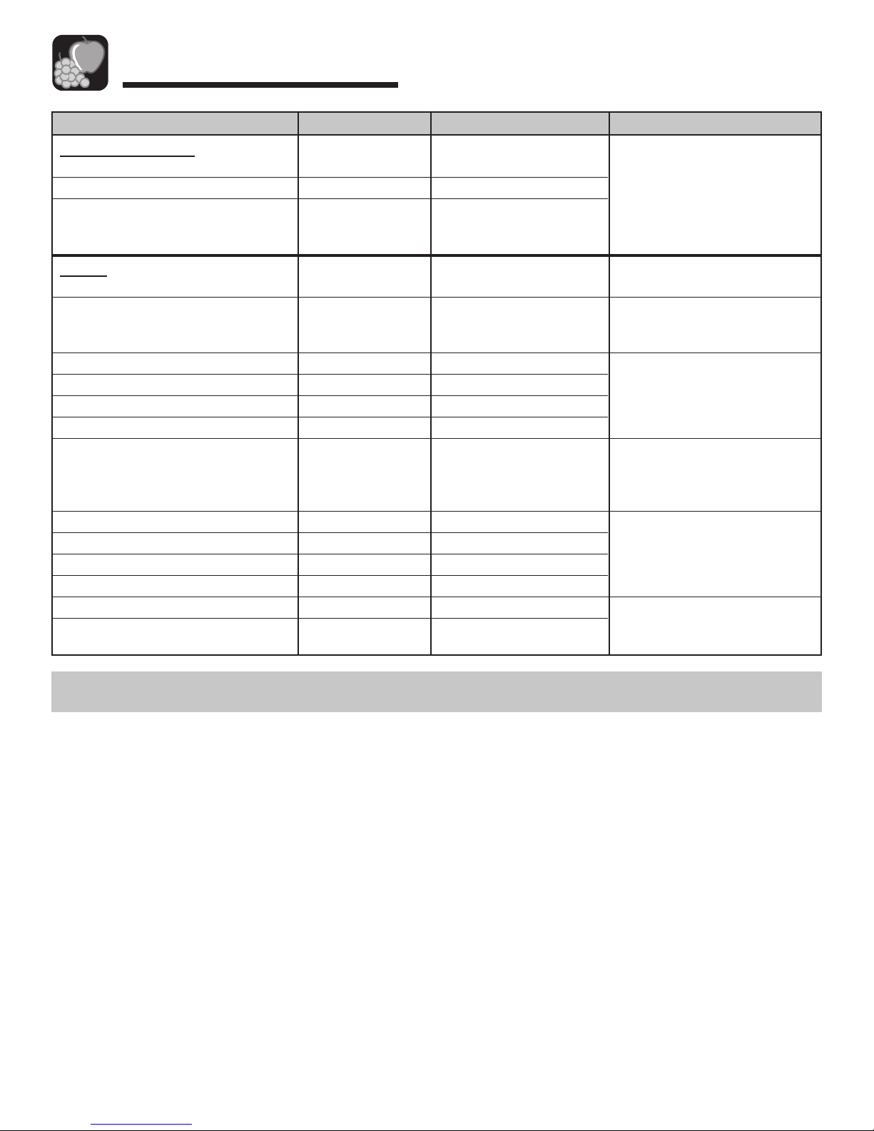
13
Food Storage Tips
FOODS
POULTRY AND FISH
Chicken and Turkey, whole
Chicken and Turkey, pieces
Fish
MEATS
Bacon
Beef or lamb, ground
Beef or lamb, roast and steak
Ham, fully cooked, whole
half
slices
Luncheon meat
Pork, roast
Pork, chops
Sausage, ground
Sausage, smoked
Veal
Frankfurters
REFRIGERATOR
1-2 days
1-2 days
1-2 days
7 days
1-2 days
3-5 days
7 days
5 days
3 days
3-5 days
3-5 days
3-5 days
1-2 days
7 days
3-5 days
7 days
FREEZER
12 months
9 months
2-6 months
1 month
3-4 months
6-9 months
1-2 months
1-2 months
1-2 months
1-2 months
4-6 months
4 months
1-2 months
1-2 months
4-6 months
1 month
STORAGE TIPS
Keep in original packaging for
refrigeration. Place in the Meat
and Cheese Drawer. When
freezing longer than 2 weeks,
overwrap with freezer wrap.
Fresh meats can be kept in
original packaging for
refrigeration.
Place in the Meat and Cheese
Drawer. When freezing longer
than 2 weeks, overwrap with
freezer wrap.
Unopened, vacuum-packed
luncheon meat may be kept up
to 2 weeks in the Meat and
Cheese Drawer.
Processed meats should be
tightly wrapped and stored in
the Meat and Cheese Drawer.
Sources: United States Department of Agriculture; Food Marketing Institute;
Cooperative Extension Service, Iowa State University
14
Storing the Refrigerator
Vacations*
If you will be gone for a month or less, leave the controls at
the usual settings.
During longer absences:
1. Remove all food.
2. Shut off the ice maker (if installed) and the valve where
you tapped into the water line to supply the refrigerator.
3. Disconnect the refrigerator from the electrical outlet.
4. Bleed the water from the ice maker fill line and dry the
ice maker thoroughly.
Care & Cleaning
Refer to the chart on the following page for specific
refrigerator cleaning guidelines.
3. To prevent an accidental spill, drain any defrost water
which may have accumulated in the defrost drain pan.
This pan is located behind the front base grille. To
remove the pan, push down on both sides and slide it out.
4. If your model has been connected to a water supply for
an automatic ice maker, turn off the water before moving
the refrigerator.
5. Pull the refrigerator out from the wall.
Replacing a Light Bulb
Always use a standard 40 watt appliance bulb.
Fresh Food Compartment
The light bulb is located under the top of the fresh food
compartment.
• Remove light shield, if present.
• Unscrew the light bulb and replace.
Moving*
When moving, follow instructions listed in Vacations. In
addition, remove and carefully pack any items that are
easily removable. Ship the refrigerator in an upright
position with the doors taped shut.
Water damage due to improper disconnection and
drainage may cause mold/mildew growth.
WARNING
* If using an automatic ice maker, discard first two or three ice harvests, when refrigerator is put back into service.
To avoid electrical shock which can cause severe
personal injury or death:
• Disconnect the power cord before moving or
cleaning the refrigerator.
• Disconnect the power cord before replacing the light
bulb.
WARNING
To avoid personal injury:
•Wear gloves when changing a light bulb to protect
against possible broken glass.
CAUTION
5. Clean and dry the refrigerator thoroughly.
6. Leave the doors open to prevent odors.
No Clean™ Condenser
A clean condenser means more efficient refrigerator
operation. Thanks to the unique design of the No Clean™
Condenser, there is no longer a need for routine
condenser cleaning in normal home usage surroundings.
Some operating environments may be particularly dusty or
greasy. In these situations, the condenser can be
periodically cleaned to insure maximum efficiency.
Cleaning Under the Refrigerator
1. Disconnect the power cord.
2. Raise the locking feet, if engaged (see page 3).
Freezer Compartment
The freezer light (select models) is located on the back wall,
near the upper right corner.
To remove the bulb cover:
• Grasp the top and bottom of the bulb cover. Press in the
areas of the attachment tabs, applying enough pressure to
unhook the tabs. At the same time, pivot the cover down
and remove.
• Unscrew the lightbulb and replace.
• Replace the bulb cover by pivoting it back into place and
snapping the tabs into the appropriate slots.
PART
REFRIGERATOR
EXTERIOR
Front base grille
Condenser
Door handles
Painted metal surfaces:
Cabinet, doors
Defrost Drain Pan
Stainless steel doors
(select models)
Stainless look exterior
finish
15
Care & Cleaning
Refrigerator Cleaning Chart
To avoid electrical shock which can cause severe
personal injury or death, disconnect power to
refrigerator before cleaning. After cleaning, connect
power.
WARNING
To avoid personal injury or property damage, observe the
following:
• Do not touch refrigerated surfaces with wet or damp
hands, they may stick to the cold metal surfaces.
• Before cleaning the freezer, allow it to warm up.
• Allow glass shelves to warm up before immersing in
warm water.
CAUTION
* Brand names are the trademarks of the respective manufacturer
REFRIGERATOR AND
FREEZER INTERIOR
Door gasket
Glass shelves
Interior and door liner
Drawers, bins,
shelves, etc.
Baking soda and warm water.
Mild detergent and warm water.
Mild detergent and warm water.
Glass cleaner.
Mild liquid sprays.
Mild detergent and warm water.
Baking soda and warm water.
Mild detergent and warm water.
Use 1-2 tablespoons baking soda per quart of water. Be
sure to wring out excess water from sponge or cloth
when cleaning around controls, lights, or electrical parts.
Allow the glass to warm up to room temperature
before immersing in warm water. Never use hot
water.
See above for baking soda solution.
Do not use abrasive cleaners, concentrated detergents,
bleaches, cleaning waxes, solvents or polish cleaners to
clean the refrigerator interior.
Dry thoroughly.
Do not wash in automatic dishwasher.
Mild detergent and warm water.
Mild liquid sprays.
Vacuum cleaner attachment.
Cleaning brush (Part No.
20001017) available from your
dealer.
Mild detergent and warm water.
Mild liquid sprays.
Mild detergent and warm water.
Mild liquid sprays.
Mild detergent and warm water.
Light cleaning: mild detergent
and warm water.
Moderate soil: Bon Ami*.
Discolorations: Cameo
Stainless Steel Cleaner*.
Wash with a clean, soft cloth or
sponge and a mild detergent in
warm water.
TIPS AND PRECAUTIONS
Remove the front base grille (see page 3).
No need for cleaning unless environment is particularly
greasy, dusty or there is significant pet traffic in the home
(see page 14).
Dry with a clean, soft cloth.
Do not wipe the refrigerator with a soiled dishwashing
cloth or wet towel. These may leave residue that can
scratch and weaken the paint.
Do not use scouring pads, powdered cleansers, bleach or
cleaners containing bleach. These products can scratch
and erode the paint finish.
Do not wax plastic or vinyl parts.
Routine cleaning usually not necessary unless environment is particularly humid or dusty. Pan should be
drained and cleaned prior to moving the refrigerator (see
page 14).
Use a soft cloth or sponge.
Always wipe with the grain of the stainless steel.
Do not use chlorine bleach or a cleaning product that
contains chlorine bleach.
After cleaning, rinse and dry. To retore luster and remove
streaks follow with Stainless Steel Magic Spray* (Part No.
20000008).
Do not use abrasive or harsh cleaners, or cleaners
designed for Stainless Steel. Dry thoroughly with a soft
cloth.
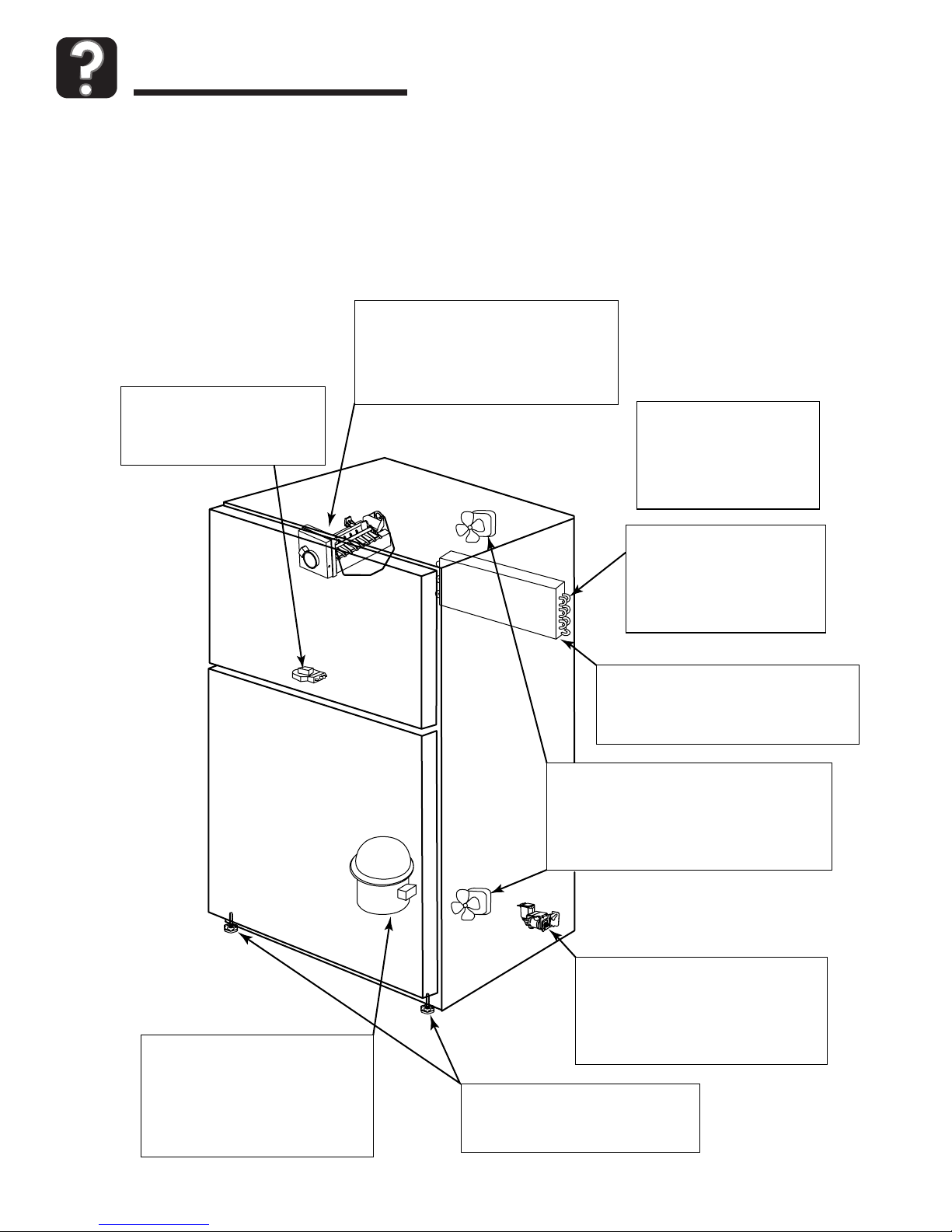
16
Troubleshooting
Normal Operating Sounds
Improvements in refrigeration design may produce sounds in your new refrigerator that are different or were not
present in an older model. These improvements were made to create a refrigerator that is better at preserving food,
is more energy efficient, and is quieter overall. Because new units run quieter, sounds may be detected that were
present in older units, but were masked by higher sound levels. Many of these sounds are normal. Please note that
the surfaces adjacent to a refrigerator, such as hard walls, floors and cabinetry may make these sounds seem even
louder. The following are some of the normal sounds that may be noticed in a new refrigerator.
DEFROST TIMER: Frost-free
refrigerators have a defrost timer
that will generate a clicking
sound when it cycles the unit
into and out of defrost cycle.
ICE MAKER: (if equipped) The ice maker
will occasionally generate a rattling sound
when the ice cubes are ready to drop down
into the ice bin. Also, the motor that ejects
the ice from its tray prior to dropping the
ice may also be detectable. These are
normal sounds necessary for making ice.
FREEZER COMPARTMENT
CONTRACTION AND EXPANSION: A popping sound may
occur in the freezer when the
unit starts up due to contraction
or expansion of the materials in
the freezer area.
DEFROST HEATER: During
the automatic defrost cycle, a
sizzling sound may be heard
as water droplets come into
contact with the defrost
heater. This is a normal
sound heard during defrost.
REFRIGERANT FLOW: The flow of the
refrigerant in your refrigerator may cause a
gurgling or rattling sound when the unit is
running or just after the unit cycles off. The
refrigerant is still flowing in the tubing.
AIRFLOW SOUNDS: Both the freezer
evaporator fan and the condenser fan at the
bottom of the cabinet will create airflow
sounds. The evaporator fan is circulating the
cold air throughout the refrigerator and freezer
compartments. The condenser fan is removing
the heat generated when the unit is cooled.
WATER VALVE (if equipped): A buzzing
sound may be detected in the back of
the unit when the ice dispenser calls for
the water valve to open to fill the ice
maker tray. Following the ejection of the
ice, there may be some water dripping
sounds when the trays are being filled.
CABINET LEVELING: An unlevel
cabinet may cause rattling or vibrating
noises. This can be fixed by adjusting
the wheels or levelers properly.
COMPRESSOR: In order for a new
refrigerator to run more efficiently,
the refrigeration system may run
longer to keep food at the desired
temperatures for freshness. That
new, high efficiency compressor may
run longer and generate sounds such
as a higher pitched hum or pulsation.

17
Troubleshooting
Review this chart of troubleshooting tips first…you may not need to call for service at all.
PROBLEM
Won’t run
Runs too long,
too frequently
Light not working
Visible glow in
freezer vents
Warm air from
cabinet bottom
Cabinet vibrates
Odor in cabinet
Noise, sounds
and vibrations
Freezer, refrigerator
too warm
Freezer, refrigerator
too cold
POSSIBLE CAUSES
Power cord not plugged in.
No power to outlet.
Fresh food control set to
“OFF” position.
Refrigerator is in automatic defrost.
Room temperature less than 55° F
(13° C).
Today’s refrigerators start and stop more
often to maintain even temperatures.
Normal at startup for new or recently
installed units.
Prolonged or frequent door openings.
Door not sealing.
Front base grille blocked.
Bulb burned out.
No power to unit.
Appearance of a red glow or reflection
is normal during the defrost cycle.
This is normal air flow for condenser
circulation.
Cabinet not level. Weak floor.
Odor producing foods not covered.
Normal noise.
Cabinet not level.
Control set too warm.
Prolonged door openings.
Room temperature less than 55° F
(13° C).
Products with high sugar content may
not harden completely when frozen.
Control set too cold.
WHAT TO DO
Push plug into outlet.
Replace fuse, reset circuit breaker.
Set fresh food control (see page 7).
Wait 25 minutes for defrost cycle to end.
Relocate unit to proper climate (see Installation on
page 3).
Wait 24 hours for refrigerator to completely cool down
(see Temperature Controls on page 7).
This is normal. Minimize door openings.
Check to see if something is preventing door from closing.
Unblock to allow warm air to exit unit.
Unplug refrigerator and change bulb (see page 14).
Check to see if power cord is completely plugged in
properly.
Level cabinet (see page 3).
Cover or wrap odorous foods tightly. Clean cabinet.
See Normal Operating Sounds (page 16).
Level cabinet (see page 3).
Adjust temperature control (see page 7).
Minimize door openings.
Unit will not run often enough to maintain proper
temperatures.
Adjust temperature control (see page 7).
GENERAL OPERATIONNOISETEMPERATURE
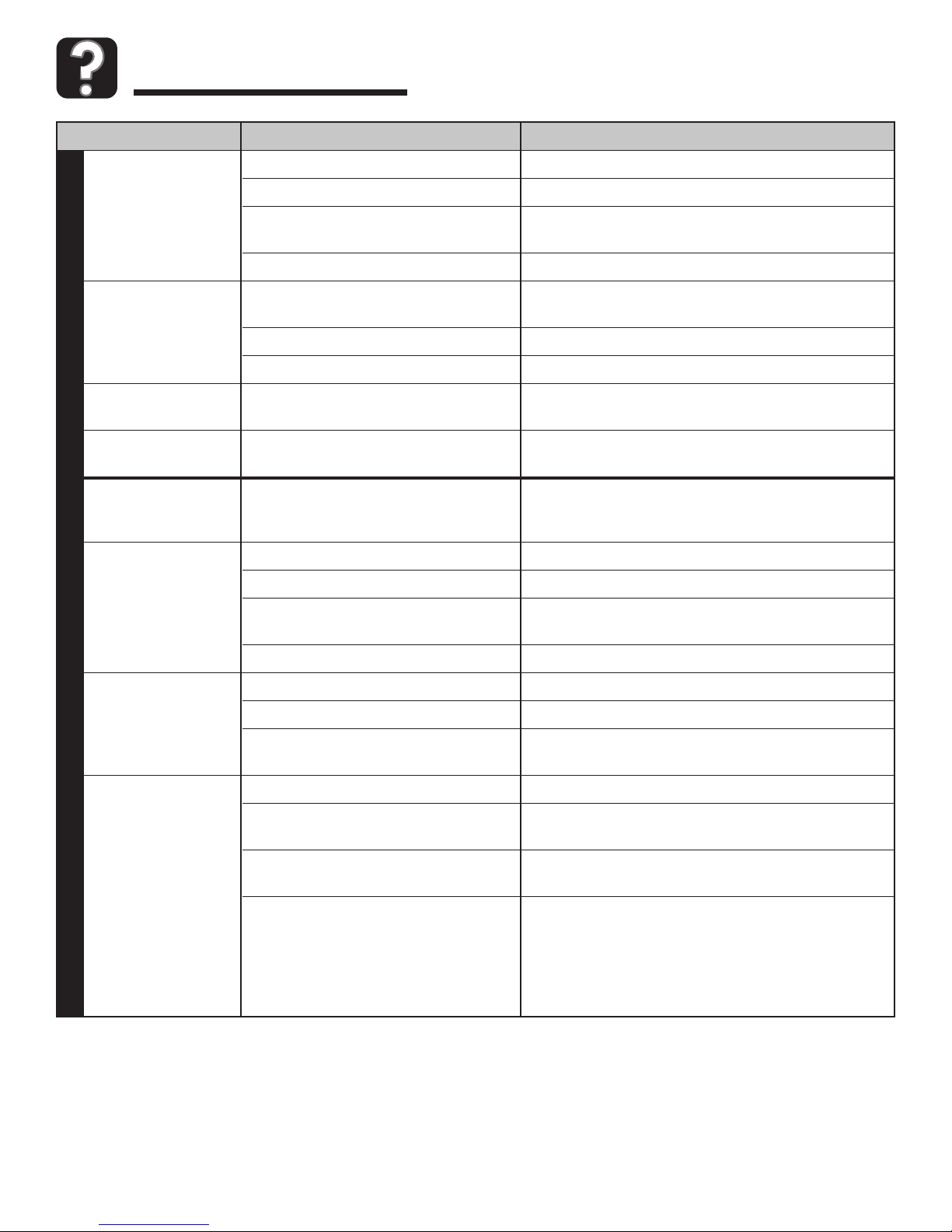
18
Troubleshooting
PROBLEM
Automatic icemaker
not working
Ice cubes have
odor/taste
Ice cubes
sticking in tray
Ice cubes
evaporating
Moisture on
cabinet surface
between doors
Moisture on inside
cabinet walls
or in crisper
Foods dry out
Excessive moisture
in crisper
POSSIBLE CAUSES
Sensor arm in up position.
Cabinet not level.
Water supply not connected or
restricted.
Freezer too warm.
Old cubes.
Bad water quality.
Food transmitted odor/taste to ice.
Residue from minerals in the water.
Limited use of ice.
Not unusual during periods of high
humidity.
Hot humid weather.
Frequent or prolonged door openings.
Door not closed properly.
Food not wrapped properly.
Crisper not tightly closed.
Temperature controls set too cold.
Packages not wrapped or sealed
properly.
Hot, humid weather.
Humidity slide on crisper needs
adjustment.
Too much moisture on fresh produce
before storing.
Foods not stored properly.
WHAT TO DO
Adjust sensor arm down to “ON” position.
Level unit (see page 3).
Connect water supply, or clear obstructions.
Adjust freezer temperature control (see page 7).
Discard; ice cubes may absorb odors which affect
taste.
Contact local water treatment company.
Wrap foods tightly.
Wipe trays with vinegar-soaked cloth until clean.
Dump old ice cubes.
Normal.
Minimize door openings.
Check to see if something is preventing door from
closing.
Wrap or cover all foods tightly.
Close crisper all the way.
Adjust temperature controls (see page 7).
Wrap or cover all foods tightly.
Minimize door openings.
Slide control to “Fruit” setting to allow more moisture
to leave the drawer.
Do not wash items prior to storage. Wait to wash
fresh items until right before use.
Store leafy vegetables in a loosely closed plastic bag.
Store items with an outer skin (i.e. apples, oranges,
pears, grapes, cucumbers, etc.) in a vented bag or
unwrapped in the drawer.
Store mushrooms and berries in original vented
cartons or boxes, not in plastic bags.
ICEMOISTURE
19
Warranty & Service
What is Not Covered By These
Warranties:
1. Conditions and damages resulting from any of the following:
a. Improper installation, delivery, or maintenance.
b. Any repair, modification, alteration, or adjustment not
authorized by the manufacturer or an authorized servicer.
c. Misuse, abuse, accidents, or unreasonable use.
d. Incorrect electric current, voltage, or supply.
e. Improper setting of any control.
2. Warranties are void if the original serial numbers have
been removed, altered or cannot be readily determined.
3. Light bulbs.
4. Products purchased for commercial or industrial use.
5. The cost of service or service call to:
a. Correct installation errors.
b. Instruct the user on the proper use of the product.
c. Transport the appliance to the servicer.
6. Consequential or incidental damages sustained by any
person as a result of any breach of these warranties.
Some states do not allow the exclusion or limitation of
consequential or incidental damages, so the above
exclusion may not apply.
If You Need Service
• Call the dealer from whom your appliance was purchased
or call Maytag ServicesSMat 1-800-688-1120 U.S.A. and
Canada, to locate an authorized servicer.
• Be sure to retain proof of purchase to verify warranty
status. Refer to Warranty for further information on owner’s
responsibilities for warranty service.
• If the dealer or service company cannot resolve the
problem, write to Maytag Services
SM
, Attn: CAIR®Center,
P.O. Box 2370, Cleveland, TN 37320-2370 or call
1-800-688-1120 U.S.A. and Canada.
• User’s guides, service manuals and parts information are
available from Maytag Services
SM
, Maytag Customer
Assistance.
Warranty
Full One Year Warranty Parts and Labor
One (1) year - From the original retail purchase date,
any part which fails in normal home use will be repaired
or replaced free of charge.
Ice Maker - When purchased with the refrigerator and
installed by the dealer, the ice maker will be considered
part of the refrigerator for warranty purposes.
Limited Warranty Major Refrigeration Components
Second Through Fifth Year - After the first year from
the date of original purchase, through the fifth year, the
manufacturer will repair or replace, at its option, free of
charge for parts and labor, any part of the sealed
refrigeration system (consisting of the compressor,
evaporator, condenser, drier and connecting tubing) and
the cabinet liner (exclusive of the door liner) which fail in
normal home use. All other costs, including mileage,
transportation, trip charge and diagnostic charge, if
required, shall be the responsibility of the owner.
Limitations of Liability
The warrantor shall not be liable for any incidental or
consequential damages, including food loss. Some states
do not allow the exclusion or limitation of consequential
damages, so the above limitation or exclusion may not
apply to you.
The specific warranties expressed above are the ONLY
warranties provided by the manufacturer. These warranties
give you specific legal rights, and you may also have other
rights which vary from state to state.
Note
•When writing or calling about a service problem, please
include the following information:
a. Your name, address and telephone number;
b. Model number and serial number;
c. Name and address of your dealer or servicer;
d. A clear description of the problem you are having;
e. Proof of purchase (sales receipt).
Note
The full warranty and the limited warranties apply
when the refrigerator is located in the United States or
Canada. Refrigerators located elsewhere are covered
by the limited warranties only including parts that fail
during the first year.
 Loading...