

Magic Chef CGR3520ADT, CGR3510ADH, CGR3520ADH, CGR3740ADH, CGR3740ADL Installation Instructions
...Page 1

INSTALLER: LEAVE THESE INSTRUCTIONS WITH THE APPLIANCE
' WIDE FREE-STANDING
AND SLIDE-IN
PLEASE.KEEP THIS MANUAL FOR FUTURE REFERENCE
THEMANUALIS INTENDEDTOASSISTIN THEINITIALINSTALLATIONAND ADJUSTMENTSOF THEF
!!!!i !ii!!i
CLEARANCE DIMENSIONS
Rangemaybeinstalledwithzeroinchesclearanceadjacentto (against)combustibleconstructionatther_
on the sidesbelowthe cooktop.For comp!eteinformationin regardto the installationof wallcabinets ab(
range and clearances to combustiblewall above the cooking top see the installation drawings. For SJ
CONSIDERATIONSdo notinstalla rangeinany combustiblecabinetrywhichisnot inaccordwith the inst_
drawings.
* NOTE:30 inchdimensionbetweencookingtop andwall cabinetshownonillustrationdoes notapplyto
withanelevatedoven.The30inchdimensionmaybe reducedto notlessthan24incheswhenthewall cabin
domestichomeare protectedwithfireproofmaterialsin accordancewithAmericanNationalStandards- N
FuelGasCodeor in mobilehomeswhentheyareprotectedwithfireproofmaterialsinaccordancewiththeF
Standardfor MobileHomeConstructionandSafety.
i
Toeliminatetheriskofburnsorfirebyreachingoverheatedsurfaceunits,cabinetstoragespacelocatedab(
surfaceunitsshouldbeavoided.If cabinetstorageisto be provided,the riskcanbereducedby installinga
hoodthat projects horizontallya minimumof 5 inches beyondthe bottomof thecabinets.
CAUTION:SOMECABINETSANDBUILDINGMATERIALSARENOTDESIGNEDTOWITHSTANDTHE
PRODUCED BY THE NORMAL SAFE OPERATION OF A LISTED APPLIANCE. DISCOLORATIOI
DAMAGE,SUCHAS DELAMINATION,MAYOCCUR.
YOUR RANGE MAY NOT BE EQUIPPED WITH SOME OF THE FEATURES REFERRED r
IN THtS MANUAL.
8101P1:
(08-
Page 2

INSTALLATION DRAWINGS
I" LOCATION NON-SELF
GAS LINE
1/_" CLEANING MODELS.
FOR 120 VOLT
I" GROUNDED ELECTRICAL
OUTLET IN THIS AREA.
OUTLET MUST BE FLUSH.
AREA IS 13"W X 9"H,
FLOOR, AND 1 1/2" FROM
33" RIGHT WALL,
-,_ LOCATED 9 3/8" ABOVE
%
18" \
./ff _
21/,,', ..>"
< 25" NORMAL
36" HEIGHT DEPTH
OF ABINET
/ 30" CABINET 24"
OPENI NG CABINET
RECOMMENDEDGAS LINE
LOCATION SELF-CLEAN
MODELS.
FREE-STANDING
CABINET
23 3/4" ON CABINET TOPS WITH
MIN. FLAT SHAVE RAISED SECTION
AREA TO CLEAR TOP.
._ 23 1/2" 30"
WITH THIS DIMENSION_ " OUTLET IN THIS AREA.
FILLER STRIP OR OUTLET MUST BE FLUSH.
OPTIONAL BACKGUARD AREA IS 13"W X 9"H,
IS NOT USED.
FOR CUTOUT GREATER FLOOR, AND 1 I/2" FROM
THAN 23 I/2" USE RIGHT WALL.
FILLER KIT, K6OFILL
OR CAX6OOOAXD.
OPT IONAL BACKGUARD
KIT K6OP OR
CAX6400AXO
MAY BE USED WHEN
CUTOUT IS 25".
#'OF 25" MINIMUM
INSTALLATfON, ADJUST DEPTH
BEFORE ATTEMPTING _(_ 3MMENDEOGAS CABINET
RANGE LEVELING LEGS I / _ LINE LOCATION
TO ACCOMMODATE | / 30" CABINET 2¢" CABINET
THIS DIMENSION. IL/_ _,,,..* OPENING
CAUTION:
SOMEWHITE EUROPEAN STYLE CABINETS ARE EQUIPPED WITH
DELICATE WHITE VINYL DRAWER AND DOOR FRONTS. THE VINYL
MAY NOT BE DESIGNED TO WITHSTAND THE HEAT PRODUCED BY THE
NORMALSAFE OPERATION OF A SELF-CLEANING RANGE.
DISCOLORATION OR DELAMI NATI ON MAY OCCUR.
TO AVOID POSSIBLE DAMAGE, WE RECOklMENDINCREASING THE 30" CABINET
OPENING TO 31 1/&" MINIMUM AND USING A HEAT SHIELD KIT--CABKIT V.
THE COUNTERTOP CUT. OUT MUST REMAIN 30".
UTOUT FOR 120 VOLT
36" HEIGHT
CABINET
FORMED FRONT EDGE,
NOTE:
GROUNDED ELECTRICAL
LOCATED 9 3/8" ABOVE
SLIDE-IN
Page 3
I
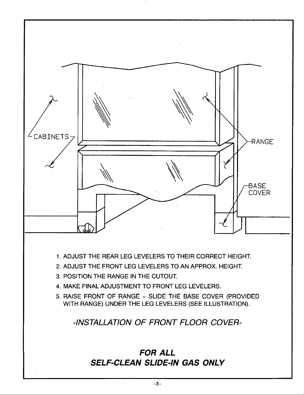
1. ADJUST THE REAR LEG LEVELERS TO THEIR CORRECT HEIGHT.
2. ADJUST THE FRONT LEG LEVELERS TO AN APPROX. HEIGHT.
3. POSITION THE RANGE IN THE CUTOUT.
COVER
4. MAKE FINAL ADJUSTMENT TO FRONT LEG LEVELERS.
5. RAISE FRONT OF RANGE - SLIDE THE BASE COVER (PROVIDED
WITH RANGE) UNDER THE LEG LEVELERS (SEE ILLUSTRATION).
-INSTALLATIONOF FRONT FLOOR COVER-
FOR ALL
SELF-CLEAN SLIDE-IN GAS ONLY
-3-
Page 4

ANY COMBUSTIBLE
I _ --- _ SURFACE
/
/
/- F
I -3o- LI
I _ (SEE NOTE ON FRONT ABOVE COOK TOP
I 'o i,L I , J I'I o"CLEARANCE
MIN. I I I i J.
""] "_- _ _-'-_" "_-'------_" I _ _ COMBUSTIBLE
i
' ' ' ' BELOWTHE COOKING
MIN. OF CABINETS
iO0 0 00'
IL I l
II| T1
li I > THE BACK AND SIDES
phil
36"
ART #9219-922
CONSTRUCTIONAND
OF THE RANGE
SURFACE.
DIMENSION "A" SIDE CLEARANCE ABOVE COOKING SURFACE
TOP BURNER RATE FOR "'CONVENTIONAL SELF-CLEAN
NATURAL GAS (SEE RATING PLATE) OVEN OVEN
9,200 BTU/HR OR LESS 0 INCHES 3 INCHES
MORE THAN 9,200 BTU/HR 1 INCH 3 INCHES
Check the range model number plate to see if the range is RECREATIONALVEHICLES
approved for installation in mobile homes and/or The installation of a range designed for recreational vehicles
recreational vehicles. If approved the following items are must conform with state or other codes or, in the absence of
applicable, such codes, with the Standard for Recreational Vehicles,
ANSI A119.2-1atest edition.
MOBILE HOMES
In Canada the range must be installed in accordance with
The installation of a range designed for mobile home CAN/CSA- Z24062- Electrical Requirements for R V's
installation must conform with the Manufactured Home (CSA Standard CAN/CSA - Z240 RV Series) and Section
Construction and Safety Standard, Title 24 CFR, Part 3280 Z240.4.2 Installation Requirements for Propane
[formerly the Federal Standard for Mobile Home Appliances and Equipment in R.V.'s (CSA Standard
Construction and Safety, Title 24 HUD, (Part 280)] or, when CAN/CSA - Z240 RV Series).
such standard is not applicable, the Standard for
Manufactured Home installations, ANSi A225.1/NFPA LOCATINGTHE RANGE
501A, or with local codes. Do not set range over holes in the floor or other locations
In Canada the range must be installed in accordance with where it may be subject to strong drafts. Any opening in the
the current CSA Standard C22.1 - Canadian Electrical Code wall behind the range and in the floor under the range should
Part 1and Section 7240.4.1 - installation Requirements for air is not obstructed.
Gas Burning Appliances in Mobile Homes (CSA Standard
CAN/CSA- Z240MH). NOTE: A range should NOT be installed over kitchen
be sealed. Make sure the flow of combustion or ventilation
carpeting.
-4-
Page 5

ANTI-TIP DEVICE INSTALLATION INSTRUCTIONS
NOTE:A riskofrangetipoverexistsiftheapplianceisnot the rangeand the levelingfootthat will engage the
installed in accordance with the installation instructions ANTI-TIP bracket,see figure 2.
provided.Theproperuseof thisdeviceminimizesthe riskof B. ForSAFETY CONSIDERATIONSas well as optimum
TIP-OVER. In using this device the consumer must still performanceadjusttherangesothatit islevel.Thismay
observethe safety precautions as stated in the USEand be checked by placing a spirit level or a large pan of
CAREMANUALandavoidusingtheovendoorand/or lower wateronthecooktoportheovenrack. Ifan adjustment
draweras a step stool, is requiredon freestanding,pull the rangeforward, tip
Installationinstructionsareprovidedforwoodandcementin the range and rotate the leveling feet as required.
either floor or wall. Any other type of construction may
require special installation techniques as deemed beforean adjustmentcanbemade.
necessaryto provideadequate fastening of the ANTI-TIP C. Tocheck the rangefor proper installationoftheanti-tip
bracketto thefloororwall. bracket: Use a flashlight and look underneath the
STEP1 - LocatingThe Bracket(see figure 1) legsisengaged inthe bracketslot.
A. Markthefloor or wallwhere either the rightor left rear D. Proceed with the remainder of the installation
"EDGE"of the rangeisto belocated, instructions.
B. Placethe BRACKET15/16"from the marked"EDGE"
towardcenterof openingand againstthe backwall as
showninfigure 1. "*,lI_,,.
C. Use the bracket as a templateand markthe required '*'_
holes,as shownin figure 1,for the typeofconstruction ANTI-T IP _f-HOLESFO_
Slide-in ranges require total removal from cabinet
bottomofthe rangeto see that one ofthe rear leveling
BRAOKET\ I)L WALL
yOUwillbe using. X "'TJIP_/, _
STEP2 - Anti-Tip BracketInstallation HOLES FOR--_---_ _ _/_ - (_, I I
A. WoodConstruction:
FLOOR /_ _--/_-,,, #1I'
1. Floor:Locatethecenterofthetwoholesidentifiedin t_1_ _,_3 t::_
figure1 as"HOLESFOR FLOOR".Drilla 1/8" pilot _ ___
holeinthe centerof eachhole(anailorawl maybe -" ___
usedif a drillis not available).Securethe ANTI-TIP _'_ __"_
bracket to the floor with the two screws provided. _ .........**,/ ,, OF RANGE
oceo0,osT
2. Wall:Locatethecenterofthetwoholesidentifiedin RANGEFOOT EDGEOF RANGE
figure 1 as "HOLES FOR WALL".Drill an angled
1/8"pilotholeinthe centerofeachholeasshownin FIGURE 1
figure2. (Anailor awl may be used if a drillis not
available).SecuretheANTI-TIPbracketto thewall
with the twoscrews providedasshown infigure 2. NOTE:USEA MINIMUMOF(2)
Proceedto STEP 3. SCREWSTOINSTALLBRACKET
1. Suitable screwsfor concrete construction can be
B. Cementor ConcreteConstruction: __M
STEP3 - RangeInstallation _' ,C_/- I
A, Alignthe rangeto itsdesignatedlocationand slide it
obtainedat a hardwarestore. Drillthe requiredsize _ BRACKET,.
holeforthescrewsobtainedintotheconcreteatthe TmRANGEi \ Ii_ / EN:rER-WGOusT
FORFLOOR",SecuretheANTI-TIPbrackettothe
centerofthe holesidentifiedinfigure t as"HOLES \ _ } [1/4' M,N. ]_/_J fW'A'LCP_ATE
floor.Proceedto STEP3. /,._Jj _,, __b-_. /
backintoposition'Makesurethatthelevelingfootisfully AR-• 92_9-76_ I
inserted into and secured by the ANTI-TIP bracket.
Note:A minimumclearanceof 1/4"is requiredbetween
/_ "_3 |- _ *" . / "'-MARKED EDGE
TO THE WALL OR FLOOR.
\ BOTTOMI , "_.JF_ ] Oi_META[..
\ F._ _ /SLIDE IN TO SECUREI_ I t
FIGURE2
-5-
Page 6

CONNECTING THE RANGE
ELECTRICSUPPLY NATURALGAS SUPPLYLINE MUSTHAVEA NATURAL
The appliance, when installed, must be electrically GAS SERVICE REGULATOR. INLET PRESSURE TO
groundedinaccordancewith localcodesor,intheabsence MAXIMUM OF 14 INCHES WATER COLUMN (0.5
oflocalcodes,withtheNationalElectricalCode,ANSI/NFPA POUNDS PER SQUARE INCH (P.S.I.) LIQUEFIED
70. PETROLEUM (L.P.)/PROPANE GAS SUPPLY LINE
In Canadathe range must be installedin accordancewith MUST HAVE A L.P. GAS PRESSURE REGULATOR.
thecurrentCSAStandardC22.1-CanadianElectricalCode INLET PRESSURETO THIS APPLIANCE SHOULD BE
Part1. REDUCED TO A MAXIMUM OF 14 INCHES WATER
ELECTRICALSUPPLYCONNECTION: PRESSURE REGULATOR AND OTHER GAS
The rangerequires120volts,60 cyclealternatingcurrent COMPONENTSINTHIS APPLIANCEAND CAN RESULT
fromanoutletcapableof supplying15 amperes. INA GAS LEAK.
THIS APPLIANCE SHOULD BE REDUCED TO A
COLUMN (0.5 P.S.I.).INLET PRESSURESIN EXCESS
OF 0.5 P.S.I. CAN DAMAGE THE APPLIANCE
a. A GAS CUTOFF VALVE SHOULD BE PUT IN AN
ACCESSIBLE LOCATION IN THE SUPPLY LINE
AHEAD OF THE RANGE, FOR TURNING ON AND
TURNING OFF GAS SUPPLY, If range is to be
connectedto housepipingwithflexibleor semi-rigid
metal connectorsfor gas appliances,CONNECTOR
NUTS MUST NOT BECONNECTED DIRECTLYTO
PIPE THREADS. THE CONNECTORS MUST BE
INSTALLEDWITHADAPTORSPROVIDEDWITHTHE
CONNECTOR.
b. The house piping and/or range connectorused to
connecttherangetothemaingassupplymustbeclean,
freeofmetalshavings,rust,dirtandliquids(oilorwater).
Dirt, etc.in the supply linescan work its way into the
range manifold and in turn cause failure of the gas
valvesorcontrolsandclog burnersandor pilot orifices.
CAUTION: DO NOT LIFT OR MOVE RANGE BY
DOOR HANDLES,OR BACKGUARD,
GAS SUPPLY
InstallationofthisrangemustconformwithIocalcodeser,in c. Turnoff all pilotsand main gas valve of other gas
the absenceof localcodes,withthe NationalFuel Gas appliances.
Code,ANSI Z223.1-1atestedition.
In Canadathe rangemustbe installedin accordancewith
the currentCGA StandardCAN/CGA.B149 - Installation
Codesfor GasBurningAppliances and Equipmentand/or approvedfor LPGto all threads.
local codes.
GASSUPPLYCONNECTION:(SEEFIGURE3) regulator using adaptors supplied with flexible
A TRAINED SERVICEMAN OR GAS APPLIANCE connector.Rigidpipemayalsobeused.Seeratingplate
INSTALLER MUST MAKE THE GAS SUPPLY fortypeofgas rangehasbeenmanufacturedfor,
CONNECTION.Leak testing of the appliance shall be
conductedbytheinstalleraccordingtothe instructions g. Turnon maingas valve at meter,and relightpilotsat
givenin sectionh. othergas appliances.
d. Turnoffmaingasvalveatmeter.
e. Beforeconnectingrange,applypipethreadcompound
f. Connect range to gas supply at appliance pressure
-6-
Page 7

h. Apply a non-corrosiveleak detection fluid to all
jointsandfittingsinthe gasconnectionbetweenthe
supplylineshut-offvalveandtherange.Includegas
fittingsand joints in the rangeif connectionswere
disturbed during installation. Check for leaks!
_11 SUPPLY LJ_E
/_ FLEX,eLE Bubblesappearingaroundfittingsandconnections
willindicatealeak.Ifa leakappears,turnoffsupply
linegasshut-offvalve,tightenconnections,turnon
1 2 N,P.T.
_F('t_AL E ELBOW
CADAPTOR/ CAUTION:NEVERCHECK FORLEAKSWITHA
/
__'_g' @ @ ALLWHENREsIDuE.LEAKCHECKIS COMPLETE,WIPEOFF
TO CONNECTGAS SUPPLYTO 1/2 N.P.T. MALE INLET J. Adjust burnerair shutterto thewidestopeningthat
"_4kAoAP_OR willnot causethe flameto liftorblowofftheburner
TO CONNECTGAS SUPPLYTO 1/2 N,P.T, FEMALEINLET REMOVESHIPPINGSCREW-
_PPL_*,CE SH_r-,_ holdthe burnersinplace on the burner bracketfor
:_< _REPGEP_SL_i__PRESSURE _tl ii _ LOwERVALVEovEN shippingpurposesonly.(Seefigure4).
CETEL NOTE:Correctlyadjustedsealedburners,canhave
APPL tAtVCE SHUT-OFF
REGULATOR " rr-T1 L
leaks.
FLAME.
the supply line gas shut off valve, and retest for
i. Remove shipping screw from ALL top burners,
(Conventionaltopburnermodelsonly).This is to
whencold.
flamesthatwill liftor blow off withouta potoverthe
burner. These should be adjusted with a pot in
0aoe
_-LEXIBLE SUPPLY LINE ADAPTOR _ __
FIGURE4
CHECKINGPRESSUREOF HOUSE PIPING
FIGURE3 SYSTEM
APPLIANCEPRESSUREREGULATOR&ALTERNATECONNECTORS1. The applianceand its individualshutoffvalvemustbe
THEAPPLIANCEPRESSUREREGULATORONYOURRANGEMAY disconnected from the gas supply piping system during
DIFFERFROMTHISILLUSTRATION. any pressuretestingofthatsystemattestpressuresin
-7-
excessof 1/2 Ibs./sq. in. (3.5 kPa) (13.8 in. water
column).
2. The appliancemustbe isolatedfromthe gas supply
pipingsystemby closingitsindividualmanualshutoff
valveduringany pressuretestingof the gas supply
pipingsystemattestpressuresequaltoorlessthan1/2
Ibs./sq.in.(3.5 kPa) (13,8in.watercolumn).
Page 8

RANGE ADJUSTMENTS
TOP SECTION - GAS TOP PILOT TOP BURNER ADJUSTMENT
ADJUSTMENT (Seefigure5) ALL TOP BURNERVALVES:
Purgeallairfromsupplysystembyturningononetopburner The approximateheightoftheflameat the highor full-on
valve.Thenturnoffvalveandadjusttoppilotflameusing positionisshownbelow.
adjustingscrew"A"(figure5)sothatflameisevenwithtopof
flashtube.Tolighttheburner,pushandturntopburnerknob Adjustburnerair shutterto thewidestopeningthatwillnot
tothe liteposition.NOTE: Some modelshave ONLYone causethe flame to lift or blowoffthe burnerwhencold.
pilotadjustmentatthe manifoldpipe. NOTE:Correctlyadjustedsealedburners,canhaveflames
thatwillliftorblowoffwithouta potoverthe burner.These
shouldbeadjustedwitha potinplace.
ILOT ADJUSTMENT SCREW "A"
RIGHT PIL_ REMOVESHIPPING SCREW- @
_-- 3/4"FLAME
FIGURE5 CONVENTIONALBURNERS
TOP SECTION - ELECTRIC IGNITION ,J_
To operate, push and turn top burner knob to the LITE _ _ j
position.Thetopburnerwilllight.ToturnOFFsparkafterthe "]-_-[" _- AIR SHUTTFR
topburnerhas ignitedturn knobto HI setting.
-8-
SEALEDBURNERS
FIGURE6
Page 9

AIR SHUTTER-OVEN BURNER
a. The approximatelengthofthe flameof ovenburnerisa REMOVING SEALED BURNER FOR
1/2 inchdistinctinnerblueflame,figure7. ADJUSTMENT OR SERVICE:
Markignitorlocationrelativeto maintopwithpencil.This
replacingthe burner assemblyto insure that the burner is
tightenedto its original position.
_ Placeburnerwrench(partno.8312D075-60,availablefrom
your dealer or authorized service agency) over surface
burnerassemblywithignitorpositionedinsidegapinwrench
ring (figure 9). This prevents ignitor from being crushed
" when wrench tightens on burner assembly.Rotate burner
assemblyapproximatelyone-eighthturncounter-clockwise
INNERCONE and liftfrommaintop (figure10).
FIGURE7
b. Ovenburnerflame canbe checkedas follows: C/{ /'_ _L-'_'_ TO LOOSEN
thewidestopeningthatwillnotcausetheflameto lift 22_-_..
1. Yellowflameon burner- openburnerair shutterto _ _'_/22__
orblowoffthe burnerwhen cold. (See#2 on figure ZTZON
8). _INSIDE WRENCHGAP
2. Distinct blue flame but lifting - close burner air
shuttertothe pointwhere itwillnotcausetheflame TCLOTCKI_HITENCLOCKWISE-
tOliftor blowoffthe burnerwhen cold. (See #2on _,_k_ l J))
mark on the maintop is used as a reference point when
,_ _ COUNTER-CLOCKWISE
c. Theovenburnerairshutteradjustmentisthe sameon ART# A219-8L2
figure8). _.._'-;
rangeswitha gas pilotorelectricignition. _.-.ousE_,_D_..e_ - ._o_._
FIGURE9
i
I'I' TO REASSEMBLE;Replaceburner assembly in maintop
LOCK SCREW alignedwithreferencemark on maintop.
and rotate approximatelyone-eighthturn clockwise using
burnerwrench until burner locks into position with ignitor
ORFICE HOOD
\
ORIFICE HOOD ,,i,,2
AIR SHUTTER /
@
-9-
FIGURE 10
Page 10

GASCONVERSION
GENERAL APPLIANCE PRESSUREREGULATOR
All rangesandcooktopsare equippedwith doublecoaxial CONVERSION
(universal) orifices and with a convertible appliance The unitappliancepressureregulatormustbesettomatch
pressure regulator.The unit model number plate states the type gas supplyused.If convertingfromnaturalgas to
which gas it was adjustedfor at the factory.Toconvertthe LPgas,theappliancepressureregulatormustbeconverted
unittoeitherNaturalgas orLP gaswillrequireadjustmentof to regulateLPgas.Ifconvertingfrom LPgasto naturalgas,
theorificehoods,airshuttersontheburnersandadjustment the appliance pressure regulator must be converted to
of the appliancepressureregulatorconvertercap. regulate naturalgas.
TO CONVERT THE APPLIANCE PRESSURE RE-
Inletpressuretotheappliancepressureregulatorshouldbe GULATORFROMONE GAS TO ANOTHER, DO EITHER
as follows for both operation and checking of appliance (1),(2) OR (3) BELOW:YOUR UNIT WILL BEEQUIPPED
pressureregulatorsetting: WITH ONE OF THE THREE APPLIANCE PRESSURE
INLETPRESSUREIN NATURAL LP REGULATORTYPESSHOWNBELOW.
INCHESOF WATERCOLUMN GAS 'GAS 1. Removethecap,pushdownandturncounter-clockwise.
Minimum 5 11 Turnthe capoverandreinstall(figure11).
Maximum 14 14 NOTE:THE GASTYPE YOU ARECONVERTINGTO
MUSTBEVISIBLEONTHETOP OF THE INSTALLED
APPLIANCEPRESSUREREGULATORCAP.
2. Remove plasticdust cover from cap nut on top of
appliancepressureregulator.Removecap nut from
appliancepressureregulator(plasticdustcovercomes
offwith nut)."IMPORTANT"removeplasticdustcover
fromcapnutandreinstallonoppositesideofcapnut,
Reinstallcap nutto appliancepressureregulatorand
replacedustcover."CAUTION" besuremarkingforthe
typeofgastowhichappliancepressureregulatorhasjust
beenconvertedisvisibleintopofcapnutbeforereplacing
plasticdustcover.(Seefigure12.)
3. Removecapandforciblysnap outplasticplungerfrom
bottomofcap.Turnplungeroverandforciblysnapbackin
originallocation(figure13).
NOTE:PLUNGERMUSTSNAP INTO POSITION;THE
GAS TYPE YOU ARE CONVERTINGTO MUST BE
VISIBLEON LOWERSIDEOF PLUNGER.
C--T3
LP NAT
L.P. POSZTION _ NATURAL GAS. POSITION , . , ,,
FIGURE 11 FIGURE 12 FIGURE 13
ART # A219-740
./ \,
-10-
Page 11

ORIFICE CONVERSION
1. FROMNATURALGAS TO LP/PROPANEGAS: 2. FROMLP/PROPANEGASTO NATURALGAS:
a. Change the appliance pressureregulatorfrom a. ChangetheappliancepressureregulatorfromLPto
naturalto LPsetting.(Seefigure11,12or13). naturalsetting.(Seefigure11, 12or 13).
b. Screwtheburnerorificehoodsdowntightagainst b. Screwtheburnerorificehoodsawayfromthepins.
the pins.(see figure14B).Use care to notover (Seefigure14A).Approximately1 1/2to2 turns.
tighten.Overtighteningcandamagethecoaxialpin
insidetheorificehood. NOTE:On unitsusingEatonOven Safety.Valve,
screwtheburnerorificehoodsawayfrompin(see
NOTE:On unitsusingEatonOvenSafetyValve. figure14C).Approximately1 1/2to 2 turns.
screwthevalveorificehooddowntightagainstthe
valvebody.(Seefigure14D), Itisimportantthatthe c. Modelswithstandingpilots:Adjusttopburnerpilots.
hoodbeturneddownasfarasitcangotoinsurethat (Seefigure5).Turntheselectorswitchontheface
completeconversionhasoccurred, of thethermostattotheNat.position.
d. Adjustburnerair shuttertothewidestopeningthat
c. Modelswithstandingpilots:Adjustburnerpilots, willnotcausetheflameto liftorblowofftheburner
(Seefigure5).Turntheselectorswitchontheface whencold.
ofthethermostattotheLPposition.
d. Adjustburnerairshuttertothewidestopeningthat NOTE: Correctlyadjusted sealed burners,the
willnotcausetheflametoliftorblowoffthe burner flamewillliftor blowwithouta potoverthe burner.
whencold. Theseshouldbeadjustedwitha potin place.
NOTE:Correctlyadjustedsealedburners,canhave
flamesthatwillliftor blowwithouta pot overthe
burner.These shouldbe adjustedwith a pot in
place.
FOR ALL TOP BURNER AND FOR EATON
OVEN SAFETY VALVE CONVERSION OVEN SAFETY VALVE CONVERSION
(EXCEPT EATON VALVE)
_ ART# 9219-983-0 j _ ART_ 9219-_83-0
FIGURE 14A FIGURE 14B FIGURE14C FIGURE 14D
NATURALGAS LP GAS NATURALGAS LPGAS
SETTING SETTING SETTING SETTING
SERVICE- PARTSINFORMATION
WHEN YOUR RANGE REQUIRES SERVICE OR COMPLETE MODEL AND SERIAL NUMBERS OF THE
REPLACEMENTPARTS,CONTACTYOUR DEALEROR RANGE WHICH IS LOCATEDON THE RANGE MODEL
AUTHORIZEDSERVICE AGENCY.PLEASE GIVE THE NUMBERPLATE.
-11-
 Loading...