

MAG T-MAG XC Owner’s Manual

Mag International Inc.
Owner’s Manual
T-MAG XC Mini Truck Series
With 4WD Operating Instructions

FORWARD
Congratulations on your selection of the T-MAG XC series of Off-Road Mini Utility Trucks.
This Owners Manual is a component of your vehicle and it provides useful information on operation,
maintenance and safety applications. The manual is to be kept inside your vehicle for easy reference. Read it
carefully and make sure you fully understand the contents of the manual, especially the safety information.
It is forbidden to willfully refit or add other equipment to your vehicle; especially to the braking system,
steering or other mechanical parts related to the safety and the handling of the vehicle. Any direct or indirect
loss caused by the above-mentioned refitting or modification with additional equipment will be assumed at the
owners expense.
Our policy is to continually upgrade and improve our product, therefore; we reserve the right to make changes
on specific structural features at any time without any given notice. However, a new and revised manual will
become available in the event any major changes occur.
IMPORTANT NOTES
• The engine type and “EX” work number are at the right side of the engine cylinder block
• The vehicle ID Badge is located in the center under the hood
• The CARB sticker is located under the driver seat
• The customers invoice number is referenced by means of a black ID sticker
• (Inside the driver door) this reference number can be used for the ordering of parts
2

1) SPECIFICATIONS
• 1.1 Performance
• 1.2 Mass Data
• 1.3 Dimensions
• 1.4 Engine Data
• 1.5 Name Plate
• 1.6 Engine Number
• 1.7 Vehicle Identification Number (VIN)
2) VEHICLE LAYOUTS
• 2.1 Outside
• 2.2 Instruments and Controls
• 2.3 Interior
• 2.4 Engine
TABLE OF CONTENTS
3

TABLE OF CONTENTS
3) OPERATIONS (Including 4WD Option)
• 3.1 Opening the Doors
• 3.2 Windows, Rear-View Mirror and Sun Visor
• 3.3 Seats and Headrests Regulation
• 3.4 Seat Belts
• 3.5 Switches
• 3.6 Indication Lights and Dome Lights
• 3.7 Instruments
• 3.8 Rear Window Defogger
• 3.9 Cigarette Lighter and Ashtray
• 3.10 Air Conditioner
• 3.11 Glove Box
• 3.12 Radio and Tape Player
• 3.13 Parking Brake Lever
• 3.14 4WD Operating Instructions
4

TABLE OF CONTENTS
4) DRIVING
• 4.1 Exhaust Emissions and Restraining Devices
• 4.2 Inspecting Items Before Daily Use
• 4.3 Vehicle Driving Notice
• 4.4 Engine Starting
• 4.5 Operation of Transmission
• 4.6 Braking
• 4.7 Clutch, Brake and Accelerator
• 4.8 New Vehicle Driving
• 4.9 High Speed Driving
• 4.10 Driving on the Special Road
• 4.11 Cargo and Towing
5) EMERGENCY MANAGEMENT
• 5.1 Engine Overheat
• 5.2 Towing of Vehicle
• 5.3 Emergency Assistance
5

TABLE OF CONTENTS
6) DO IT YOURSELF
• 6.1 Tools Included with Vehicles
• 6.2 Use of the Jack
• 6.3 Changing the Tire
• 6.4 Spark Plug
• 6.5 Fuses
• 6.6 Replacement of Light Bulbs
7) INSPECTION AND MAINTENANCE
• 7.1 Safety Notes About Inspection and Maintenance
• 7.2 Daily Check and Maintenance
• 7.3 Periodic Inspection and Maintenance Schedule
• 7.4 Simple Inspection and Maintenance Items
8) LUBRICATION AND ANTI-CORROSION
• 8.1 Maintenance of Interior
• 8.2 Maintenance of Exterior
• 8.3 Anti-Corrosion of Vehicle
6

1) SPECIFICATIONS
1.1 Performance
Item
Data
T-MAG XC
Maximum speed (km/h)
Maximum grade ability (%) ≥20
Fuel consumption of 100km at constant speed (L/100km) ≤5.5
Minimum turning diameter (m) ≤9.5
Minimum ground clearance (mm) ≥155
Wheel camber
Wheel kingpin inclination
Wheel caster
1°30′±30′
9°30′±30′
3°00′±30′
Wheel toe in (mm) 2 ~ 5
Approach angle/Departure angle 31°/30°
Main spring leaf/thickness 3(7,7,6)
Auxiliary spring leaf/thickness 1/13
7

1.2 Mass Data
Maximum gross vehicle mass (kg) 1610 1560
Seating capacity (persons)
1.3 Dimensions
Overall length (mm) 3745 (3760#)
Overall width (mm) 1505
Overall height (mm) 1925
Wheel base (mm) 2370
Track (mm)
Front overhang (mm) 690
Rear overhang (mm) 685 (700#)
Item
Data
T-MAG XC
Curb mass (kg) 1050 1000
2
Item
Data
T-MAG XC
Front 1300
Rear 1310
Note: Data with # indicates the dimension with skirt
8

1.4 Engine Data
Item
Engine model
Engine type
Four-in-line four-stroke water-cooled multi-point
Electrically -controlled fuel injection
Cylinder bore (mm) 65.5
Stroke (mm) 72
Total displacement (ml) 970
Compression ratio 8.8
Rated output (kW/r/min) 35.5/5000
Maximum torque (Nm/r/min)
Minimum fuel consumption (g/kWh)
Fuel Unleaded gasoline
Item Quantity Item Quantity
Engine oil 2.8 Liters Transmission fluid
Coolant 4.5 Liters Fuel tank 36 Liters
Data
DA465Q
74/3000~3500
275
1.3 Liters
9

1.5 Name Plate
1.6 Engine Number
1.7 Vehicle Identification Number (VIN)
The name plate is fixed on the bracket of wiper.
The engine number is stamped on the engine cylinder of the inlet manifold side.
The Vehicle Identification Number (VIN) is stamped on the upper surface of the right plate in the
engine cabin.
10
2) VEHICLE LAYOUTS
2.1 Outside
• Hood
• Front windshield wiper
• Outside rear-view mirrors
• Side windows
• Antenna
• Front fog lights*
• Headlights/Position lights
• Turn-signal lights
• Reversing lights
• Stop lights/Position lights
• Turn-signal lights (Hazard lights)
• Door lock
• License plate lights
• Rear fog lights
• Tires *Note: Equipment may vary with each vehicle
11

2.2 Instruments and Controls
1) Lighting switch/
Turn-signal
switch
2) Combination
meter
3) Cluster
instruments
4) Front windshield
wiper and washer
switch
5) Selection dial
6) N/A
7) Mode selection
dials
8) Temperature
control dials
9) N/A
10) Glove box
11) Loud speaker cover
12) Side defogger
13) Front fog light
switch
14) N/A
15) Rear fog light
switch
16) Hood release lever
17) Horn
18) Shift knob
19) Cigarette lighter
20) Parking brake lever
21) A/C switch
22) Cap holder
23) Ashtray
24) Radio player
25) N/A
Note: The equipment may vary
with each vehicle
12
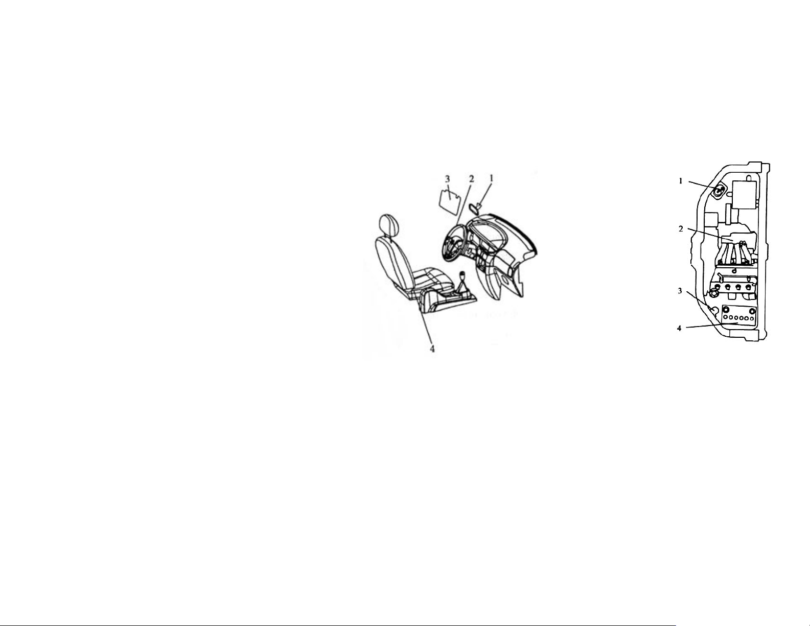
2.3 Interior
1) Inside rear-view
mirror
2) Steering wheel
3) Sun visors
4) Driver’s seat
2.4 Engine
1) Oil Filter
2) Engine
3) Ignition coil
4) Battery
13
3) OPERATIONS
3.1 Opening the Doors
1. Key
Key provided is applicable to all doors, ignition switch and fuel filler cap locks.
2. Door locks
a) Operation from outside the vehicle
There are two methods to lock the front doors; they are as follows:
b) To unlock the front door, turn the key toward front of vehicle.
c) Operation from inside the vehicle
Press the inside door lock button down to lock the door, pull up the door lock button to
unlock the door.
I. Close the door, insert the key and turn it toward rear of the vehicle.
II. Press the inside door lock button down while pulling the outside handle up, close the
door.
14
3. Fuel cap
The fuel cap is located on the on rear passenger side of the vehicle.
WARNING!!!
NEVER ALLOW SPARKS OR OPEN FLAMES NEAR THE VEHICLE WHEN REFUELING.
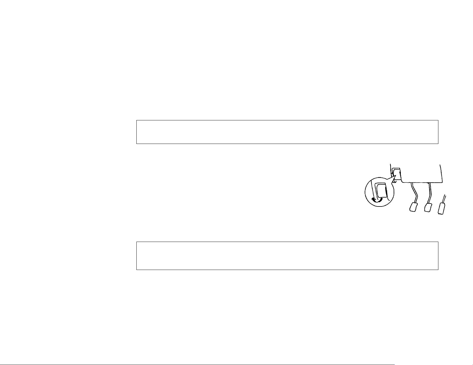
4. Hood latch
1) To open
a) Put down the wiper if it is up.
b) Pull up the control handle of the hood latch located on the
lower left of the instrument panel. (The hood may bounce)
c) Put your hand in the gap between the hood and the body;
counter rotate the handle on the hood latch support to open.
Support the hood by inserting the support bar in its slot.
WARNING!!!
ONLY OPEN THE HOOD WHEN THE WIPERS ARE IN THE DOWN POSITION.
FAILURE TO DO SO MAY CAUSE PAINT DAMAGE.
15

WARNING!!!
THE SUPPORT BAR MAY DISENGAGE THE HOOD IF IT IS LIFTED BY A STRONG WIND.
(Always insert the support bar into the hole provided specifically for this purpose)
SUPPORTING THE HOOD AT ANY OTHER LOCATION COULD RESULT
IN THE SUPPORT BAR SLIPPING OUT AND LEAD TO AN ACCIDENT.
2) To Close
a) Support the hood, release the support bar. Then secure the support bar to the clips
located on the body.
b) Slowly lower the hood to a position 300mm above the closed position, and then let it
drop.
c) Confirm that the hood is completely locked.
WARNING!!!
KEEP HANDS AND OBJECTS AWAY WHILE CLOSING THE HOOD.
BEFORE DRIVING, MAKE SURE THAT THE HOOD IS SECURELY LOCKED.
PRESS FIRMLY DOWN ON THE HOOD TO CLOSE.
16
3.2 Windows, Rearview Mirror and Sun Visor
1. Window options
a) Manual windows
Turn the window crank clockwise to
roll window down; turn
counter-clockwise to roll window up.
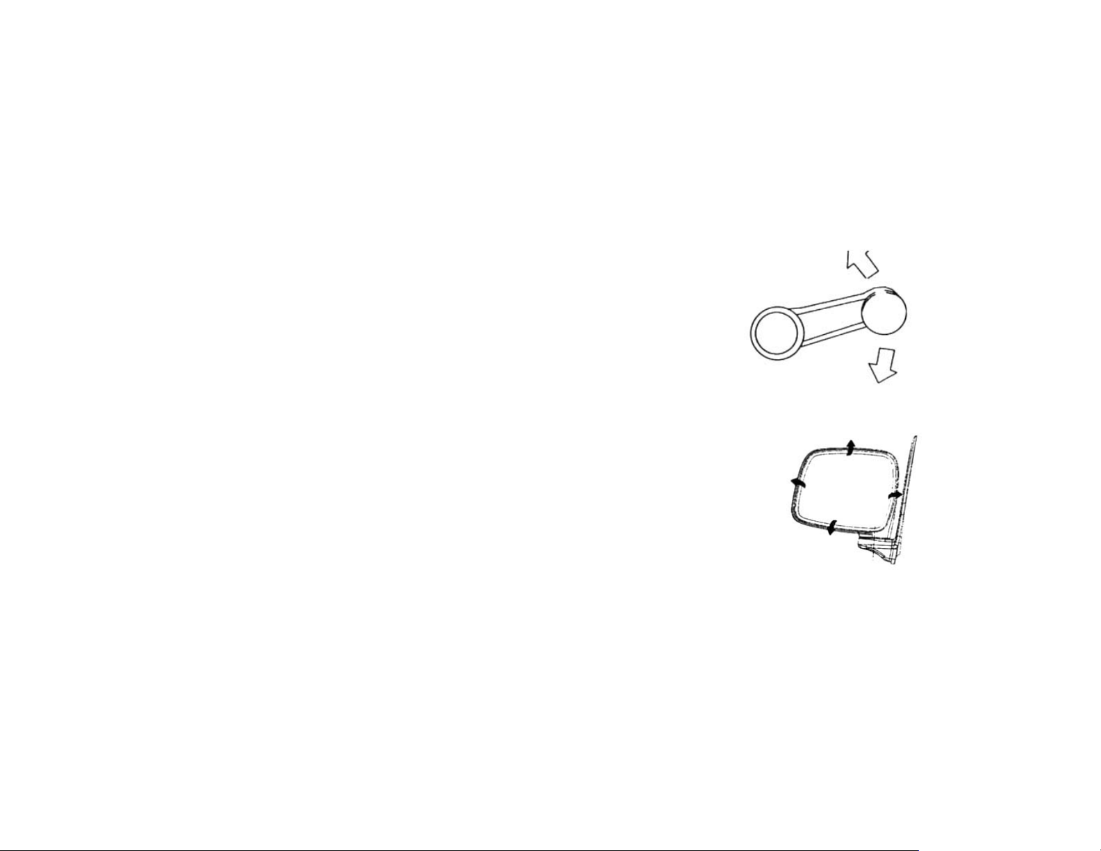
2. Rearview mirror
a) Outside rearview mirror
The outside rearview mirror can be
turned upward, downward, left and
right to adjust to a suitable position.
17
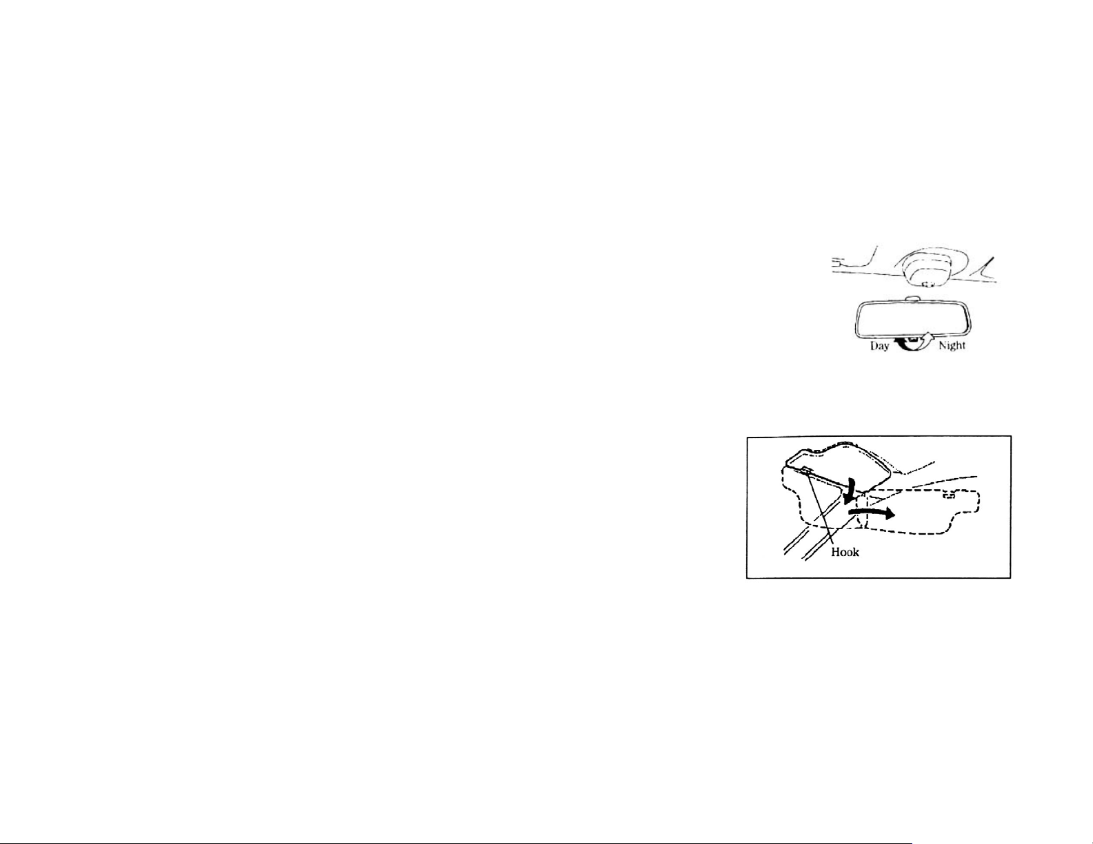
b) Inside rearview mirror
The inside mirror is located in the front upper to the
driver’s seat. It can be turned upward, downward, left and
right to a suitable position. Please adjust the knob under
the mirror to prevent the light of the rear vehicle from
blinding the driver eyes while driving at night.
3. Sun visor
a) To be used to shelter sunlight not only
from front, but also from the side, when
moved away from the hook.
18
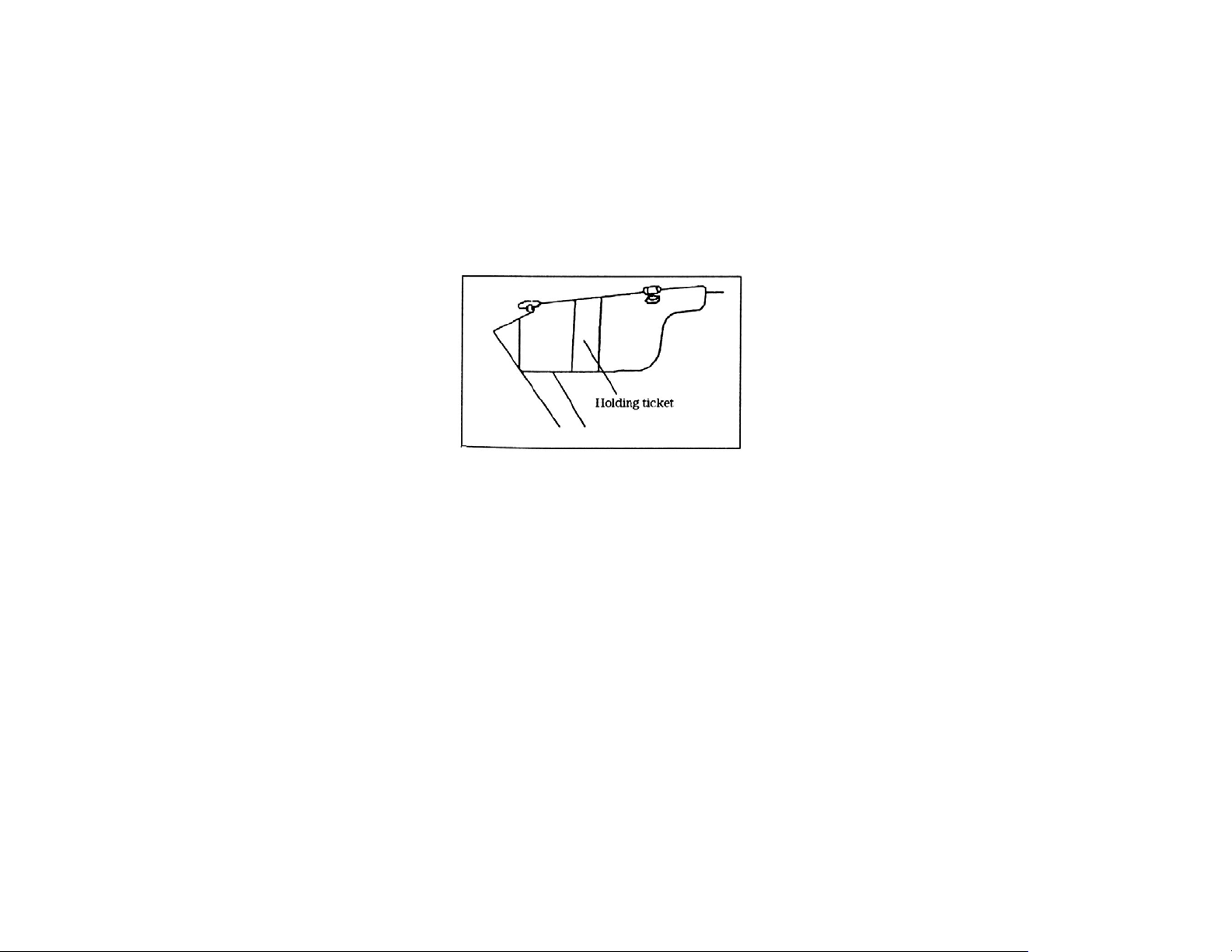
b) The clip to hold the visor is located on the reverse side of the sun visor on driver’s side.
c) A mirror dressing is located at the back of the sun visor on the passenger side.
19
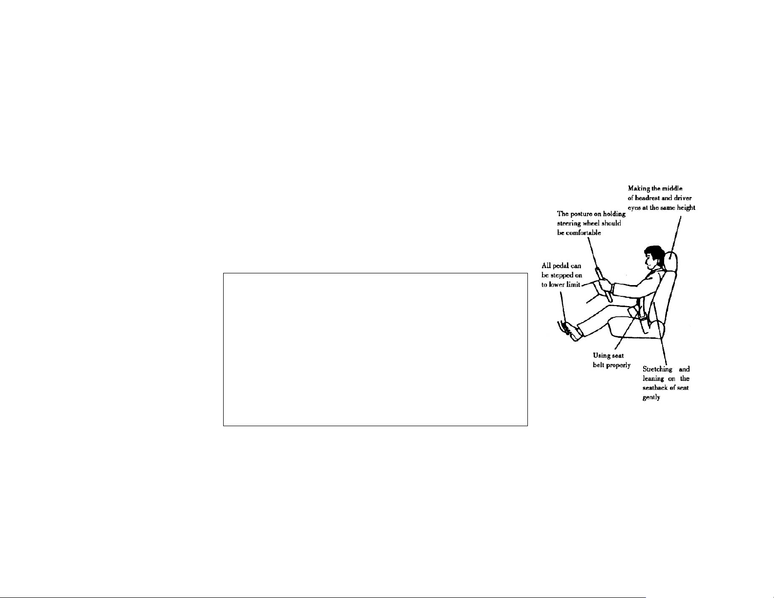
3.3 Seats and Headrests Regulation
1. Front seat adjustment
• Seat should be adjusted prior to operation of vehicle.
• Elbows should be slightly bent at steering wheel.
• Knees should be slightly bent while applying brakes or
accelerator.
• Proper use of seat belt should be adhered to at all
times.
• Neck should be positioned at headrest level.
WARNING!!!
DUE TO OPERATION INFLUENCING DRIVING, SEAT
ADJUSTMENTS MUST BE CARRIED OUT BEFORE
OPERATING THE VEHICLE.
ACCIDENTS MAY OCCUR IF SEAT IS ADJUSTED WHILE
OPERATING THE VEHICLE. ALWAYS ENSURE THE SEAT
IS FIRMLY SET TO AVOID A POTENTIAL ACCIDENT.
SERIOUS INJURY MAY BE CAUSED IF THE SEATBACK IS
RECLINED DURING OPERATION OF VEHICLE.
20

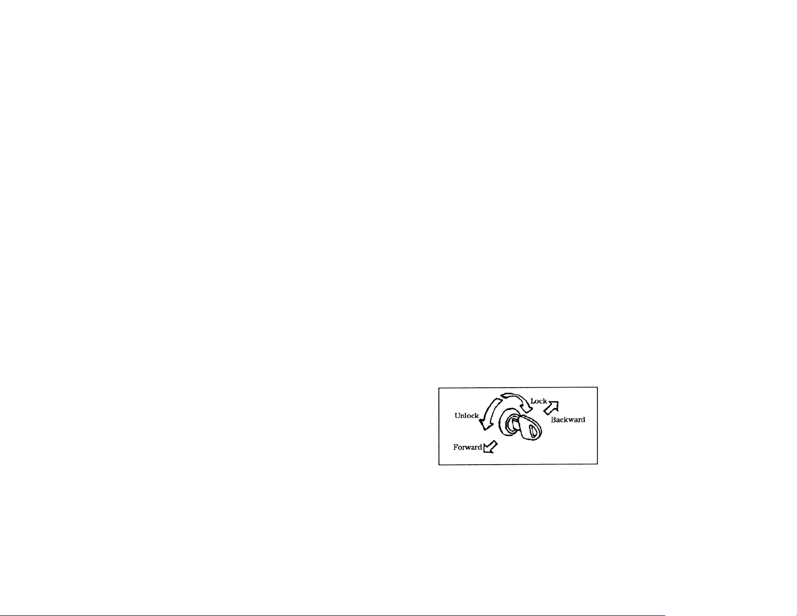
a) Adjusting seat forward and backward
Lift the lever to regulate the seat. After
regulating make sure that the seat is fixed
firmly by shaking the seat gently in
moving direction.
b) Adjust the angle of seatback
Lift the handle to regulate angle of
seatback. After regulating, make sure that
the seat is fixed firmly by shaking the
seatback gently.
21
WARNING!!!
LIFT LEVER AND PUSH THE SEATBACK TO APPROPRIATE ANGLE BY GUIDING SEAT WITH HAND;
ASSURING THE SEATBACK WILL NOT RESULT IN INJURY TO PASSENGER AS IT RETURNS TO THE
ORIGINAL POSITION.
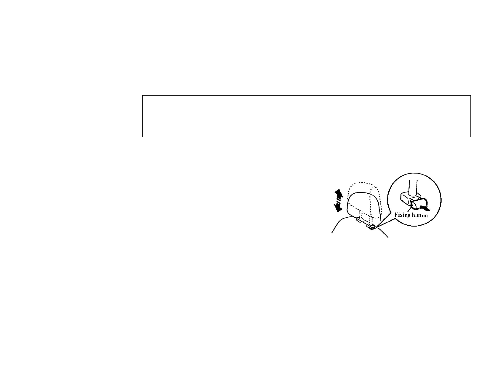
c) Adjustment of headrest
Adjust the middle of headrest assuring it is
level with driver eyes. To adjust to this
position, simply pull headrest upward. To
lower, simply push headrest down to fixed
position. While pressing the fixing button
continuously, draw the headrest upward and
remove it. To install the headrest, press the
fixing button continuously and insert the
headrest into the hole on the seatback.
22
WARNING!!!
THE MIDDLE OF THE HEADREST MUST BE ADJUSTED TO THE HEIGHTAT DRIVER’S EYE LEVEL.
TO ENSURE DRIVER’S SAFETY, DO NOT EXCEED THE HEIGHT AND DO NOT ADD CUSHION
ETC. BETWEEN THE DRIVER’S BACK AND THE SEATBACK. TO ENSURE THE DRIVERS SAFETY
DO NOT OPERATE VEHICLE IF HEADREST HAS BEEN REMOVE.
2. Regulation of rear seat
The regulation of seatback and headrest is the same with that of front seats.
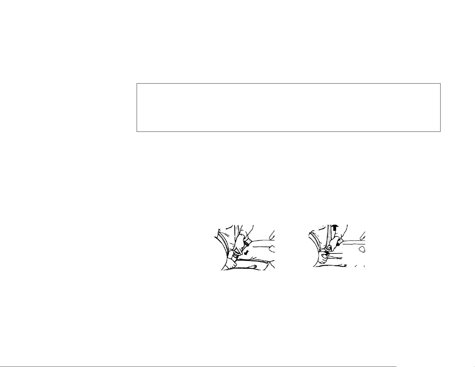
3.4 Seat Belts
1. Seat belts
Cross the seat belt over your body and press the lock buckle into the socket, until a “click” sound is
heard. Press the button on the socket to release the seat belt. The length of the belt can be adjusted
automatically through the retractor.
23
WARNING!!!
ALWAYS REMAIN RESTRAINED WITH SEAT BELT WHILE DRIVING VEHICLE. REPLACE THE
BELT WHEN WORN, DIRTY OR DAMAGED. THE SEAT BELT FOR EACH SEAT IS DESIGNED ONLY
FOR ONE PASSENGER. MODIFICATIONS ARE PROHIBITED BY LAW.
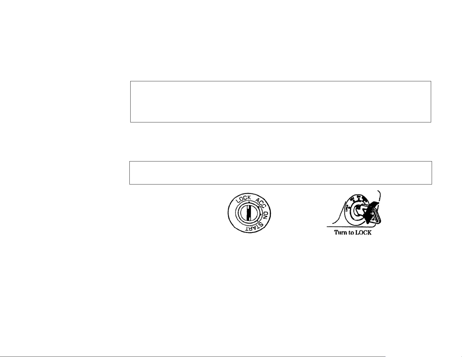
3.5 Switches
1. Ignition switch – The four locations of the ignition switch
WARNING!!!
DO NOT PLACE HANDS THROUGH STEERING WHEEL WHILE OPERATING THE IGNITION.
24

z LOCK
While vehicle is parked, the key can be pulled out from Ignition switch. You can only rotate key
to the LOCK position while key is inserted in ignition. After the key is pulled out, the ignition
switch and the steering column will be locked. To turn steering wheel, you should insert the key
and rotate it to another position clockwise. If you have the trouble unlocking the Ignition switch,
turn steering wheel to left or right side gently.
z ACC
When the key is rotated to this position, the power of accessories such as the radio will be on,
but not engine power
z ON
This is the normal position for operation. When the key is rotated to this position, all electric
systems will be on
z START
When the key is rotated to this position, the engine starts up. As soon as the engine is started,
the key must be released from the position.
25
WARNING!!!
PULLING THE KEY OUT OF IGNITION IS PROHIBITED DURING OPERATION OF VEHICLE.
PULL OUT THE KEY FROM IGNITION SWITCH AFTER PARKING. NEVER LEAVE VEHICLE
UNATTENDED WITH KEY IN IGNITION.
WARNING!!!
IF ENGINE CAN’T BE STARTED WITHIN 5 SECONDS EACH TIME, THEN START IT FOR SECOND
TIME AFTER 10 SECONDS, OTHERWISE STARTER WILL BE DAMAGED.
IF ENGINE DOES NOT OPERATE, DO NOT HOLD THE IGNITION SWITCH AT “ON” POSITION
THIS COULD DAMAGE THE BATTERY.
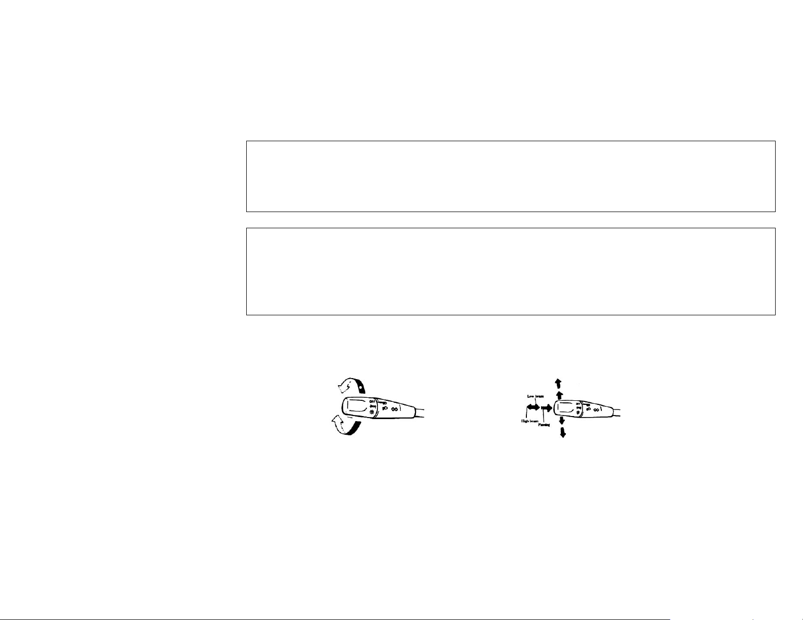
2. Headlights/Lights
Lighting switch is on the left of the steering column pipe. The operation is as follows:
26
a) Rotate the end of control lever to control the lighting system. The lighting switch has three
positions. When the switch is set to OFF lights are off. When the switch is set to the middle
position, the running lights, tail lights, license lights, lighting lights for the combination meter
turn on but headlight still off. On the third position, the head light and all of others are on.
b) When the headlights are illuminating, press down the lighting control lever, the high beam
will illuminate and high beams will signal light on the combination meters to also turn on. If you
only need the high beam to give a signal for a moment, pull up the lever gently, release the hand it
could return to the original position after giving signal
3. Turn signal light switch
Turn signal light switch and lighting switch share the same control lever. When the Ignition
switch is set to ON, pushing the lever forwards or backwards will result in the right or left side
turn signal lights flashing.
27
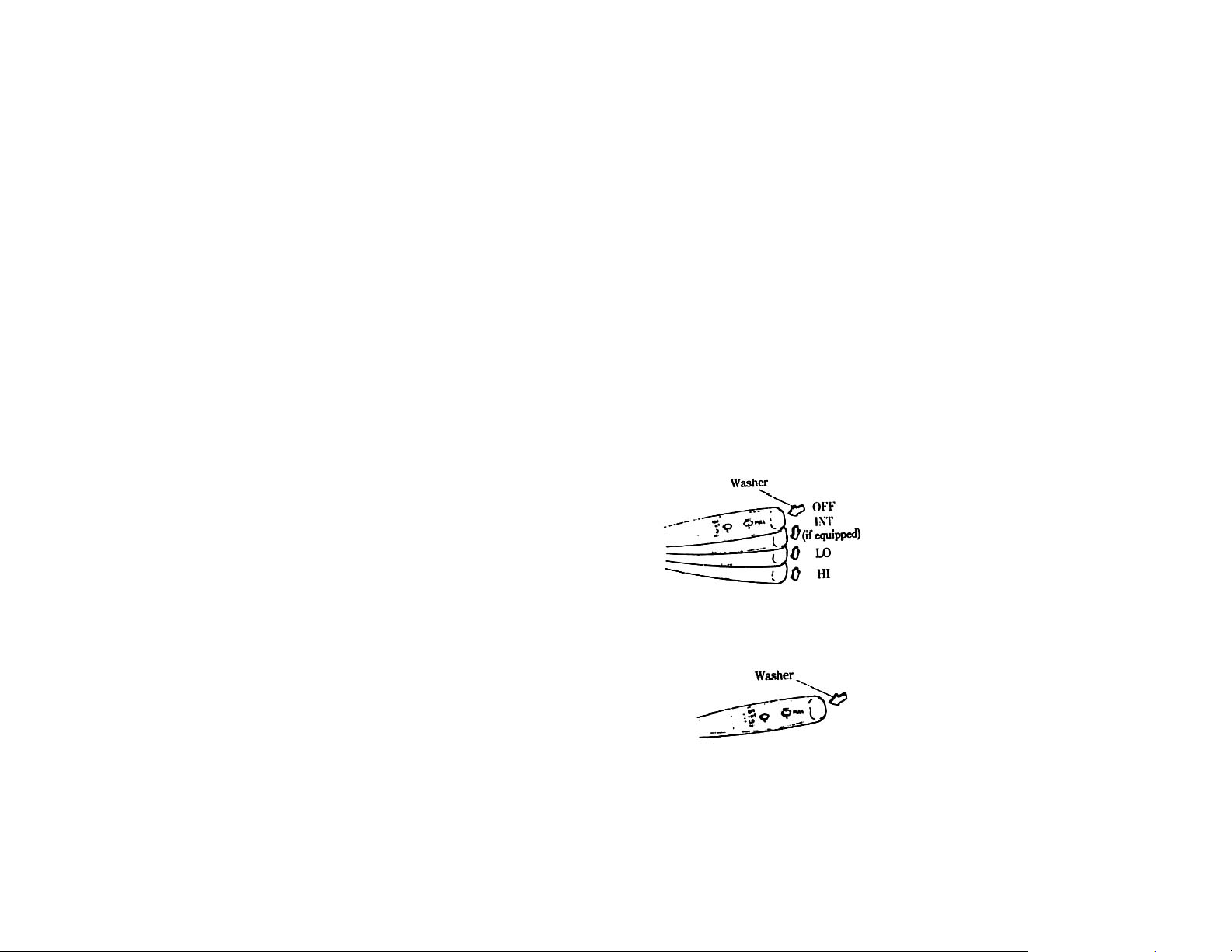
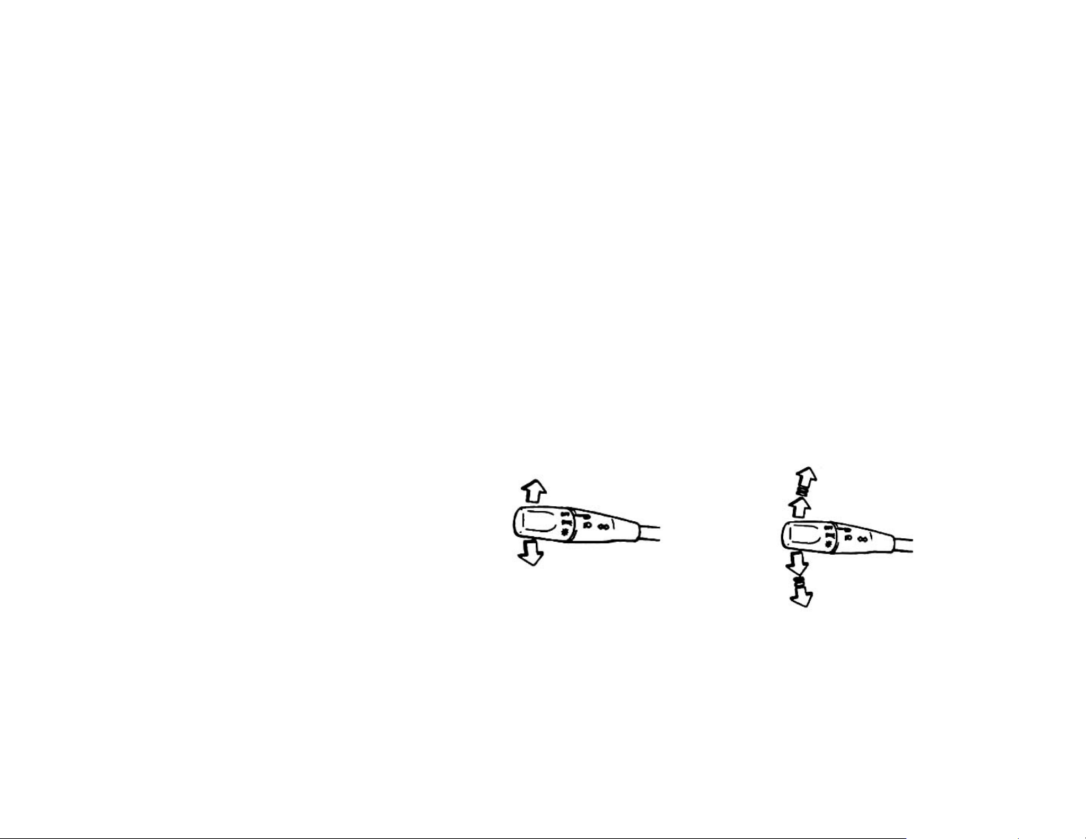
4. Wiper/Washer switch
• The wiper/washer control lever is on the right side of the steering wheel. By placing the wiper’s
control lever return to one of the three positions, the wiper will begin.
• The INT (intermittent) position is used for mist or slightly rainy weather.
• When the wiper’s control lever is on LO position, the wiper will sway slowly and
continuously.
• When the wiper’s control lever is on HI position, the wiper will sway quickly and
continuously.
• Turn the lever to OFF position to stop the wiper.
• The washer for windshield will spray when you push the switch lever up.
28

WARNING!!!
TO AVOID THE WINDSHIELD FREEZING, YOU CAN TURN ON THE DEFOGGER TO HEAT UP THE
WINDSHIELD BEFORE CLEANING.
WARNING!!!
TO AVOID DAMAGING THE WIPER AND WASHER SYSTEM, PAY ATTENTION TO THE FOLLOWING:
NEVER PUT UP THE LEVER WHEN EMPTY. THIS MAY RESULT DAMAGE TO THE WASHER MOTOR.
NEVER WIPE THE DRY WINDSHIELD. THIS MAY RESULT IN BLADE AND WINDSHIELD DAMAGE.
ALWAYS WET THE WINDSHIELD BEFORE OPERATING THE WIPER. CLEAN UP THE WIPER BLADE
BEFORE YOU OPERATE THE WIPER.CHECK THE LEVEL OF THE FLUID REGULARLY, THE
FREQUENCY OF CHECKING SHOULD INCREASE IN BAD WEATHER. IN COLD WEATHER ADD ONLY
FILL TANK TO 75% CAPACITY, FLUID WITH EXPAND AT FREEZING TEMPERATURE.
29
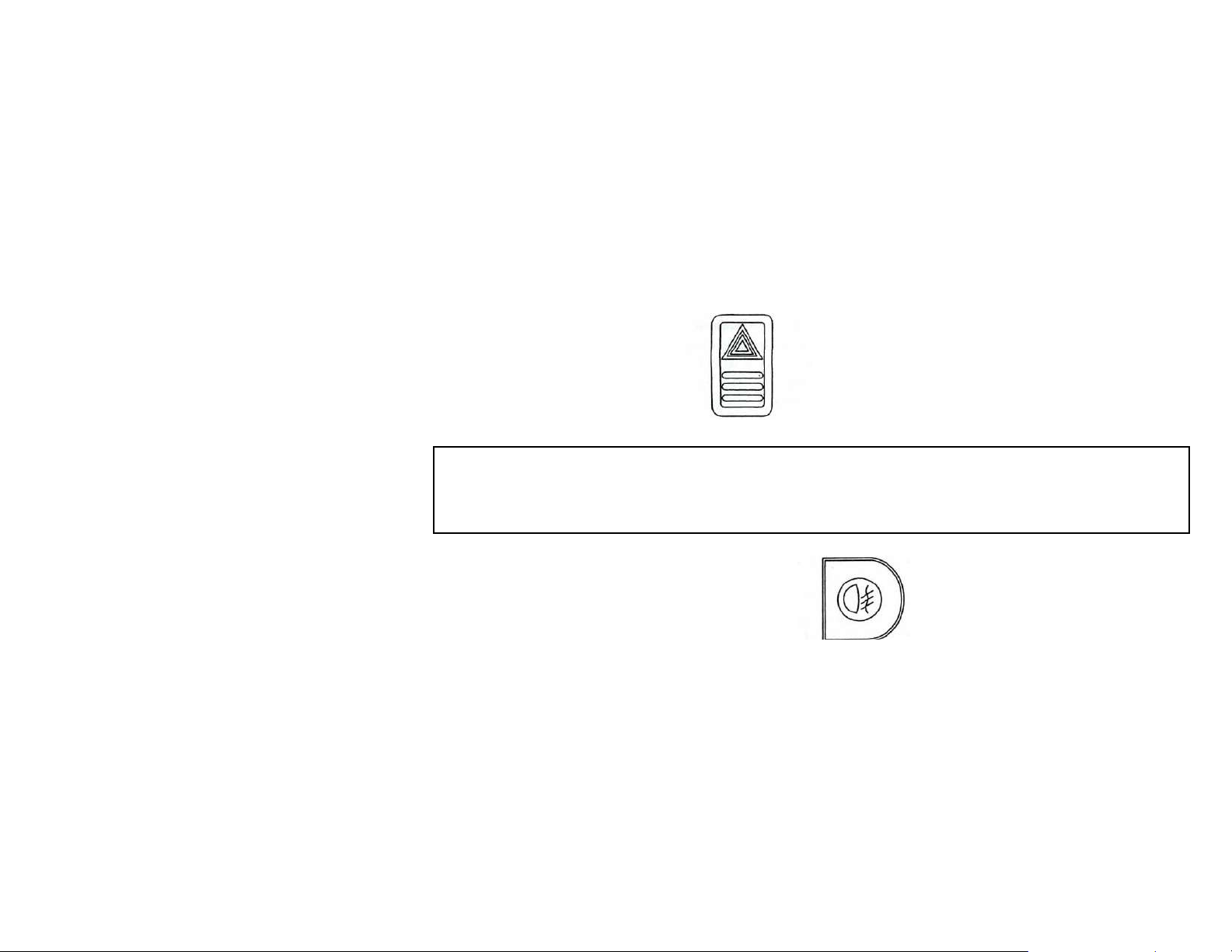
5. Hazard switch
Press this switch to turn on hazard lights. The six turn signal lights and the two turning
indicator lights shall flash. Press this switch again, the warning light signal stops.
IN CASE OF EMERGENCY, PRESS THE SWITCH, THE VEHICLE LIGHT WILL BE
6. Front fog light switch
Press this switch, the fog lights turn on.
WARNING!!!
ACTIVATED TO ALERT OTHER DRIVERS ON THE ROAD.
30
 Loading...