

MAG Sub 18A, Sub 28A, Sub 28, Sub 15, Sub 15i User Manual
...
SUBWOOFER SERIES
User Manual
Systems:
Sub 12 Sub 12A
Sub 15 Sub 15A
Sub 18 Sub 18A
Sub 28 Sub 28A
Sub 12i
Sub 15i
Sub 18i
Sub C15
Sub H12
Sub H25
Sub H28
SUBWOOFER Series User Manual rev 1.00
info@mag-audio.com
Tel./Fax: +38 044 277-47-89 www.mag-audio.com
1

Contents
Contents ............................................................................................................................................................................................2
Panel A. Dimensions ....................................................................................................................................................................4
1. Safety instructions ...................................................................................................................................................................7
2. Regulatory information ........................................................................................................................................................ 8
3. SUBWOOFER series ...............................................................................................................................................................9
3.1 Introduction ..........................................................................................................................................................................9
3.2 SUBWOOFER series speaker models ......................................................................................................................9
4. Specifications ..........................................................................................................................................................................10
5. System operation ................................................................................................................................................................... 12
5.1. Rigging .................................................................................................................................................................................12
5.2. Flying Sub 15 or Sub 18 with M10 mounting points ......................................................................................12
5.3. Eye-bolt orientation ......................................................................................................................................................12
5.4. Flying a Sub 15 or Sub 18 stack with array mount adapters .....................................................................13
5.5. Flying a Sub 15 or Sub 18 stack via flying frame .............................................................................................13
5.6. Wall mounting of Sub 12i, Sub 15i and Sub 18i.................................................................................................14
5.7. Passive speakers ..............................................................................................................................................................15
5.7.1. Passive connections ................................................................................................................................................15
5.8. Powered speakers ..........................................................................................................................................................17
5.8.1. Mains connection. ..................................................................................................................................................19
5.8.2. Signal connections. ................................................................................................................................................19
5.8.3. Sub 28A presets. .....................................................................................................................................................19
6. Standard contents ................................................................................................................................................................20
7. Accessories ................................................................................................................................................................................21
8. Warranty and assistance ................................................................................................................................................... 22
8.1. Product warranty ...........................................................................................................................................................22
8.2. Assistance ......................................................................................................................................................................... 22
info@mag-audio.com
Tel./Fax: +38 044 277-47-89 www.mag-audio.com
2
SUBWOOFER Series User Manual rev 1.00

This page has been intentionally left blank
SUBWOOFER Series User Manual rev 1.00
info@mag-audio.com
Tel./Fax: +38 044 277-47-89 www.mag-audio.com
3
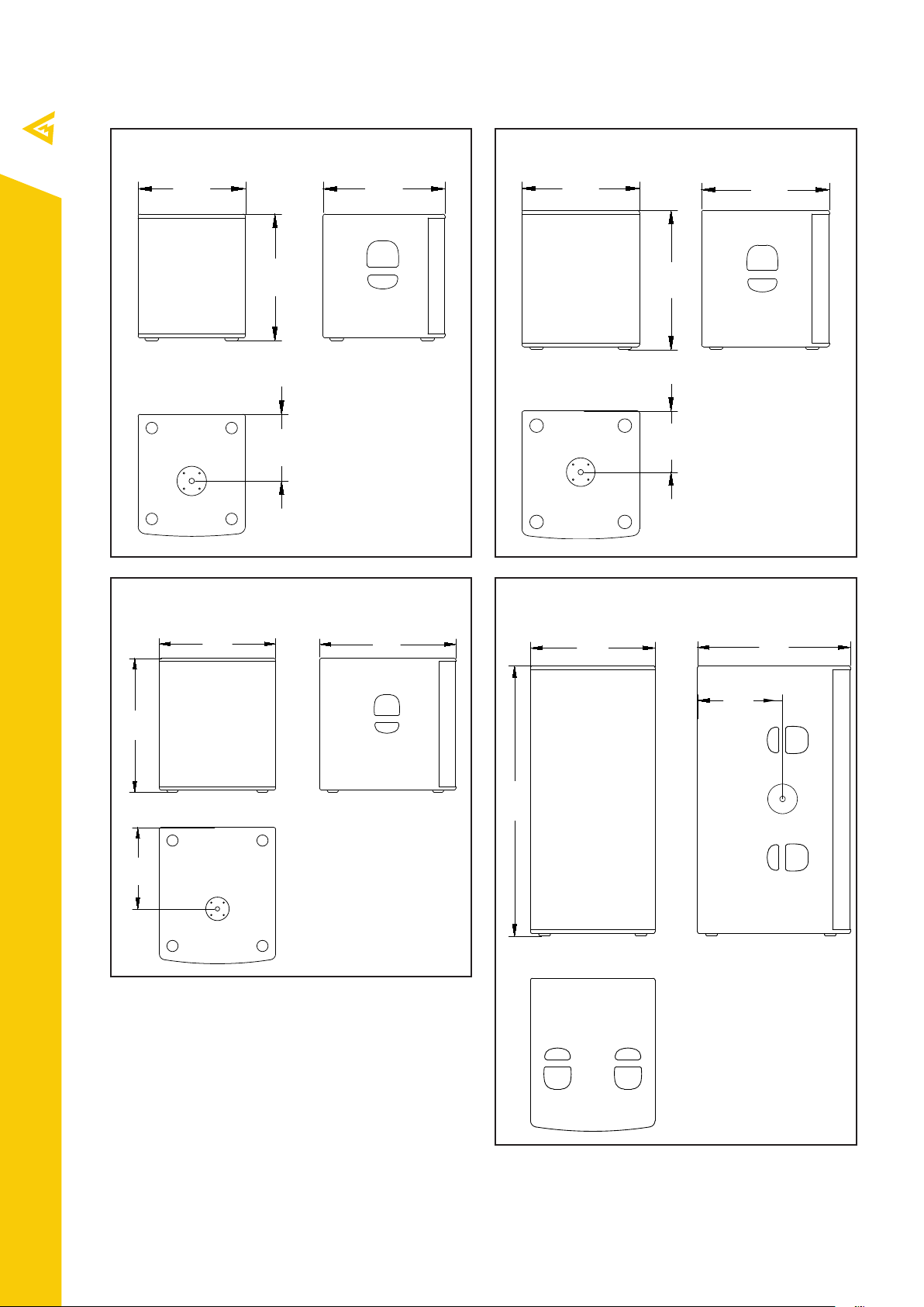
Panel A. Dimensions
390
443
440
479
530
610
621
460
242
Sub 12
Sub 12A
Sub 18
Sub 28A
Sub 15
Sub 15A
522
229
Sub 18
Sub 28A
info@mag-audio.com
Tel./Fax: +38 044 277-47-89 www.mag-audio.com
371
1150
530
651
358
4
SUBWOOFER Series User Manual rev 1.00
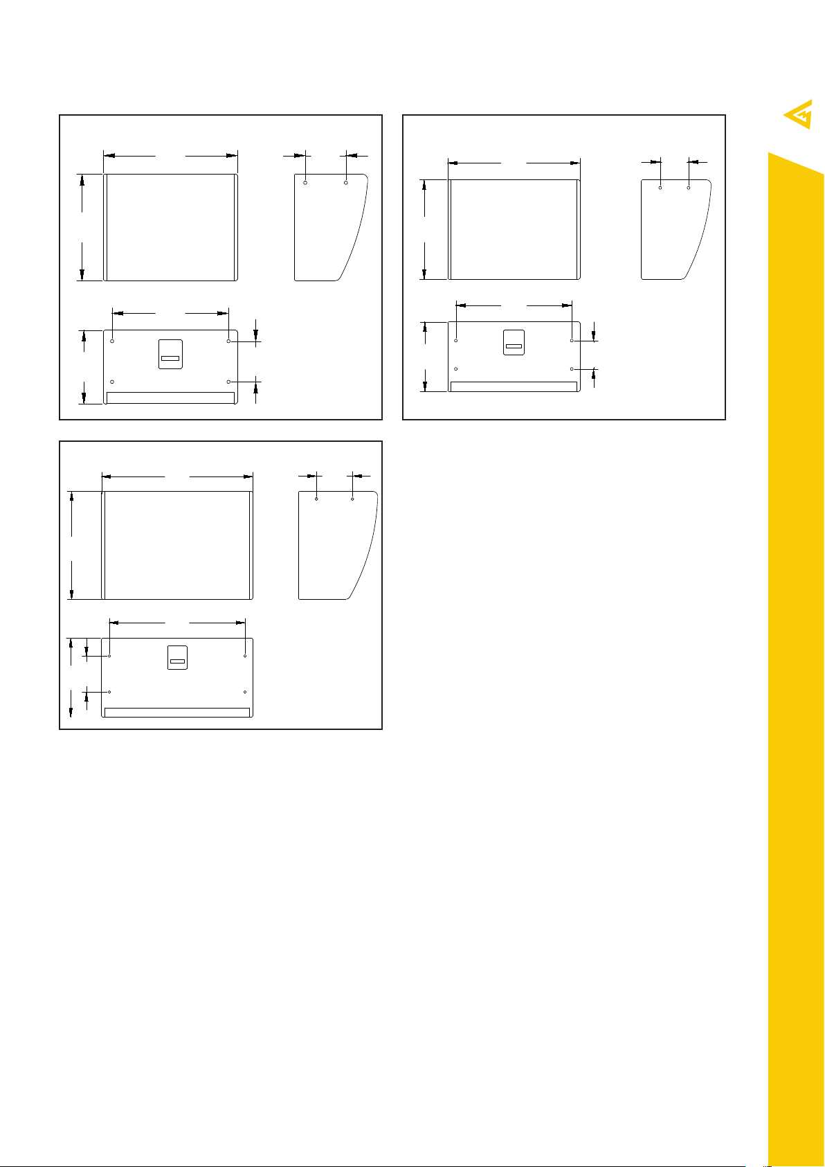
Sub 12i
610
185
486
335
700
150
370
527
840
200
600
440
Sub 15i
200
530
754
185
614
150
Sub 18i
SUBWOOFER Series User Manual rev 1.00
info@mag-audio.com
Tel./Fax: +38 044 277-47-89 www.mag-audio.com
5
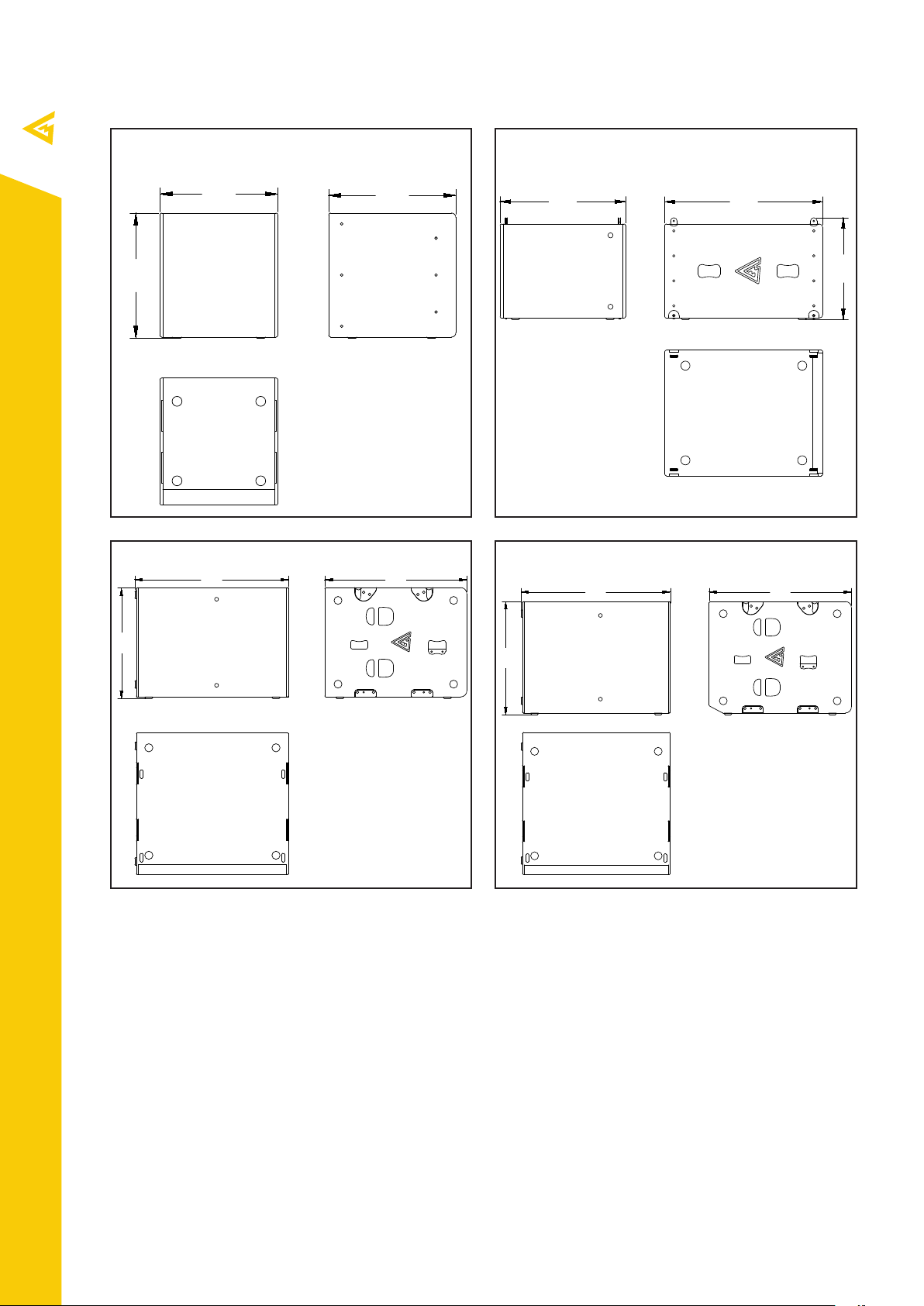
Sub C15
480
508
517
492
765
608
984
710
910
984
744
938
Sub H12
Sub H25 Sub H28
info@mag-audio.com
Tel./Fax: +38 044 277-47-89 www.mag-audio.com
6
SUBWOOFER Series User Manual rev 1.00
1. Safety instructions
CAUTION
RISK OF ELECTRIC SHOCK
= =
DO NOT OPEN
=
EXPLANATIONS OF GRAPHICAL SYMBOLS
The triangle with the lightning bolt is used to alert the
user to the risk of electric shock.
The triangle with the exclamation point is used to
alert the user to important operating or maintenance
instructions.
The CE-mark indicates the compliance with the low
voltage and electromagnetic compatibility.
Symbol for earth/ground connection.
Symbol indicating that the equipment is for indoor use
only.
Symbol for conformity with Directive 2002/96/EC and
Directive 2003/108/EC of the European Parliament on
waste electrical and electronic equipment (WEEE).
WARNING: TO REDUCE THE RISK OF ELECTRIC SHOCK,
DO NOT ATTEMPT TO OPEN ANY PART OF THE
UNIT. NO USER-SERVICEABLE PARTS INSIDE. REFER
SERVICING TO QUALIFIED SERVICE PERSONNEL.
TO COMPLETELY DISCONNECT THIS APPARATUS
FROM THE AC MAINS, DISCONNECT THE POWER
SUPPLY CORD PLUG FROM THE AC RECEPTACLE.
THE MAINS PLUG OF THE POWER SUPPLY CORD
MUST REMAIN READILY ACCESSIBLE.
DO NOT EXPOSE THIS EQUIPMENT TO RAIN OR
MOISTURE, DRIPPING OR SPLASHING LIQUIDS.
OBJECTS FILLED WITH LIQUIDS, SUCH AS VASES,
SHOULD NOT BE PLACED ON THIS APPARATUS.
CONNECTIONS TO THE MAINS SHALL BE DONE ONLY
BY AN ELECTROTECHNICALLY SKILLED PERSON
ACCORDING TO THE NATIONAL REQUIREMENTS OF
THE COUNTRIES WHERE THE UNIT IS SOLD.
IMPORTANT SAFETY INSTRUCTIONS
1. Read these instructions carefully.
2. Keep these instructions.
3. Heed all warnings.
4. Follow all instructions.
5. Do not use this equipment near water.
6. Clean only with dry cloth.
7. Do not block any ventilation openings. Install in accordance
with the manufacturer’s instructions.
8. Do not use near heat sources such as stoves, heat registers,
radiators or other equipment (including amplifiers) that produces
heat.
9. Do not use the unit near open fire sources.
10. Connect the unit only to the electric network with grounding.
Use only electic plugs that provide grounding.
11. Protect the power cord from being walked on, pinched, or
otherwise damaged.
12. Use only accessories specified by the manufacturer.
13. Unplug this unit during lightning storms or when unused for
long periods of time.
14. Refer all servicing to qualified service personnel. Servicing is
required when the system has been damaged in any way, such
as power supply cord or plug is damaged, liquid has been spilled
or objects have fallen into the unit, the unit has been exposed
to rain or moisture, does not operate normally, or has been
dropped.
15. WARNING: TO REDUCE THE RISK OF FIRE OR ELECTRIC
SHOCK, DO NOT EXPOSE THIS SYSTEM UNIT TO RAIN OR
MOISTURE.
THIS UNIT CONTAINS POTENTIALLY LETHAL VOLTAGES.
TO PREVENT ELECTRIC SHOCK OR HAZARD, DO NOT
REMOVE THE AMPLIFIER MODULE. NO USER SERVICEABLE
PARTS INSIDE. REFER SERVICING TO QUALIFIED SERVICE
PERSONNEL.
INSTALLING OF THIS UNIT MUST BE PERFORMED ONLY BY
QUALIFIED TRAINED PERSONNEL FOLLOWING APPLICABLE
SAFETY RULES. DO NOT ALLOW INSTALLATION OF THIS UNIT
IF INSTALLATION HARDWARE IS BROKEN, BENT, PARTS ARE
MISSING OR IS OTHERWISE DAMAGED.
info@mag-audio.com
Tel./Fax: +38 044 277-47-89 www.mag-audio.com
SUBWOOFER Series User Manual rev 1.00
7

2. Regulatory information
FCC COMPLIANCE NOTICE
This device complies with part 15 of the FCC
rules. Operation is subject to the following two
conditions: (1) This device may not cause harmful
interference, and (2) this device must accept any
interference received, including interference that
may cause undesired operation.
CAUTION: Changes or modifications not expressly
approved by the party responsible for compliance
could void the user’s authority to operate the
equipment.
NOTE: This equipment has been tested and found
to comply with the limits for a Class B digital device,
pursuant to part 15 of the FCC Rules. These limits are
designed to provide reasonable protection against
harmful interference in a residential installation. This
equipment generates, uses, and can radiate radio
frequency energy and, if not installed and used in
accordance with the instruction manual, may cause
harmful interference to radio communications.
However, there is no guarantee that interference
will not occur in a particular installation. If this
equipment does cause harmful interference to radio
or television reception, which can be determined
by turning the equipment o and on, the user is
encouraged to try to correct the interference by
one or more of the following measures:
- Reorient or relocate the receiving antenna.
- Increase the distance between the equipment
and receiver.
- Connect the equipment to an outlet on a
circuit dierent from that to which the receiver is
connected.
- Consult the dealer or an experienced radio/TV
technician for help.
EC DECLARATION OF CONFORMITY
Manufacturer:
MAG Audio LLC
Merezhna 2
Bila Tserkva, Kyiv region
09112 Ukraine
We declare that under our sole responsibility the
products:
Model Names:
Sub 12-4, Sub 12-8,
Sub 15-4, Sub 15-8,
Sub 18-4, Sub 18-8,
Sub 28, Sub 12A, Sub 15A,
Sub 18A, Sub 28,
Sub 12i-4, Sub 12i-8,
Sub 15i-4, Sub 15i-8,
Sub 18i-4, Sub 18i-8,
Sub C15, Sub H12,
Sub H25, Sub H28
Intended use: Professional Speaker System
Are in conformity with the provisions of the
following EC Directives, including all amendments,
and with the national legislation implementing
these directives:
- 2006/95/EC Low Voltage Directive
- 2004/108/EC Electromagnetic Compatibility Directive
- 2002/95/CE RoHs Directive
The following harmonized standards are applied:
EN 55103-1:2009 /A1:2012
EN 55014-1:2006 /A1:2009 /A2:2011
EN 55022:2010 /AC:2011
EN 61000-3-2:2006 /A1:2009 /A2: 2009
EN 61000-3-3:2013
EN 61000-3-11:2000
EN 61000-3-12:2011
EN 55103-2:2009 /IS:2012
EN 61000-4-2:2009
EN 61000-4-3:2006 /A1:2008 /IS1:2009 /A2:2010
EN 61000-4-4:2012
EN 61000-4-5:2006
EN 61000-4-6:2014
EN 61000-4-11:2004
EN 60065:2002 /A1:2006 /A11:2008 /A2:2010 /A12:2011
info@mag-audio.com
Tel./Fax: +38 044 277-47-89 www.mag-audio.com
8
Bila Tserkva,
22 January 2019
Alexey Asanov
CEO
For compliance questions: info@mag-audio.com
SUBWOOFER Series User Manual rev 1.00
 Loading...