

Page 1
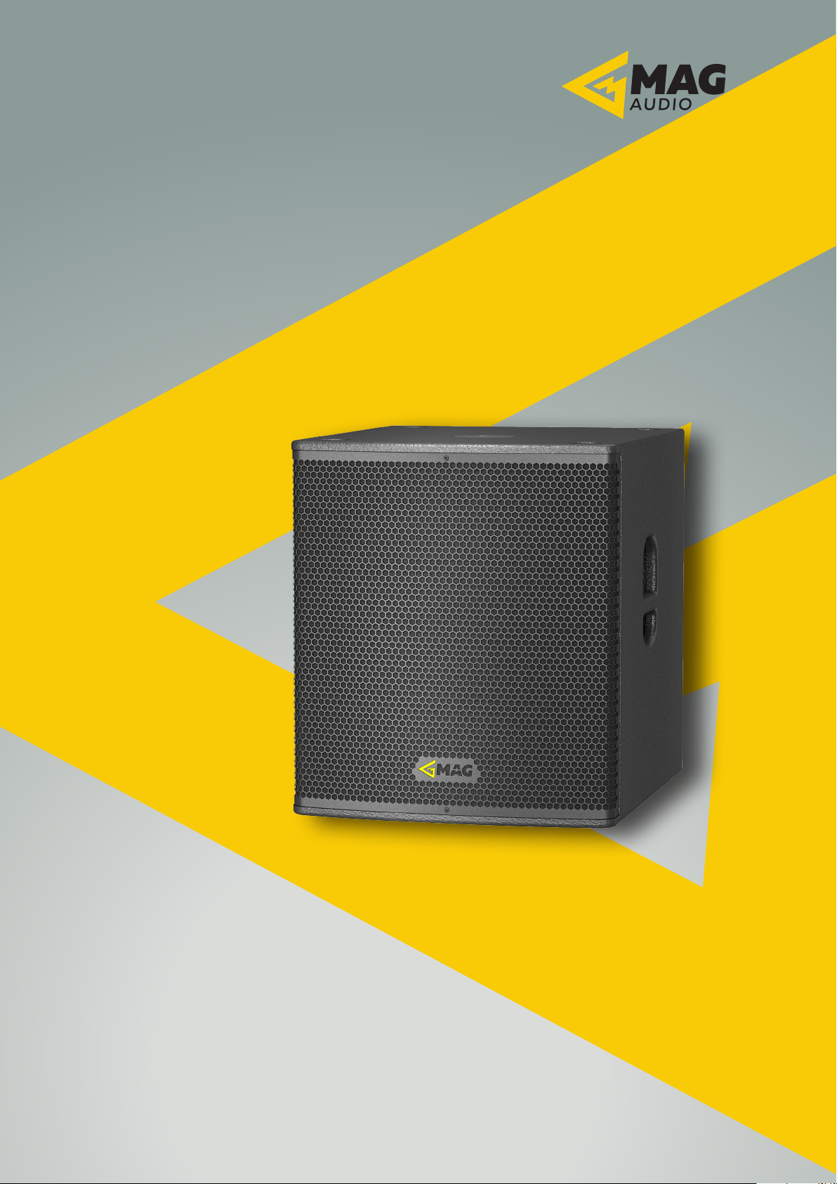
SUBWOOFER SERIES
User Manual
Systems:
Sub 12 Sub 12A
Sub 15 Sub 15A
Sub 18 Sub 18A
Sub 28 Sub 28A
Sub 12i
Sub 15i
Sub 18i
Sub C15
Sub H12
Sub H25
Sub H28
SUBWOOFER Series User Manual rev 1.00
info@mag-audio.com
Tel./Fax: +38 044 277-47-89 www.mag-audio.com
1
Page 2

Contents
Contents ............................................................................................................................................................................................2
Panel A. Dimensions ....................................................................................................................................................................4
1. Safety instructions ...................................................................................................................................................................7
2. Regulatory information ........................................................................................................................................................ 8
3. SUBWOOFER series ...............................................................................................................................................................9
3.1 Introduction ..........................................................................................................................................................................9
3.2 SUBWOOFER series speaker models ......................................................................................................................9
4. Specifications ..........................................................................................................................................................................10
5. System operation ................................................................................................................................................................... 12
5.1. Rigging .................................................................................................................................................................................12
5.2. Flying Sub 15 or Sub 18 with M10 mounting points ......................................................................................12
5.3. Eye-bolt orientation ......................................................................................................................................................12
5.4. Flying a Sub 15 or Sub 18 stack with array mount adapters .....................................................................13
5.5. Flying a Sub 15 or Sub 18 stack via flying frame .............................................................................................13
5.6. Wall mounting of Sub 12i, Sub 15i and Sub 18i.................................................................................................14
5.7. Passive speakers ..............................................................................................................................................................15
5.7.1. Passive connections ................................................................................................................................................15
5.8. Powered speakers ..........................................................................................................................................................17
5.8.1. Mains connection. ..................................................................................................................................................19
5.8.2. Signal connections. ................................................................................................................................................19
5.8.3. Sub 28A presets. .....................................................................................................................................................19
6. Standard contents ................................................................................................................................................................20
7. Accessories ................................................................................................................................................................................21
8. Warranty and assistance ................................................................................................................................................... 22
8.1. Product warranty ...........................................................................................................................................................22
8.2. Assistance ......................................................................................................................................................................... 22
Tel./Fax: +38 044 277-47-89 www.mag-audio.com
2
SUBWOOFER Series User Manual rev 1.00
Page 3

This page has been intentionally left blank
SUBWOOFER Series User Manual rev 1.00
Tel./Fax: +38 044 277-47-89 www.mag-audio.com
3
Page 4
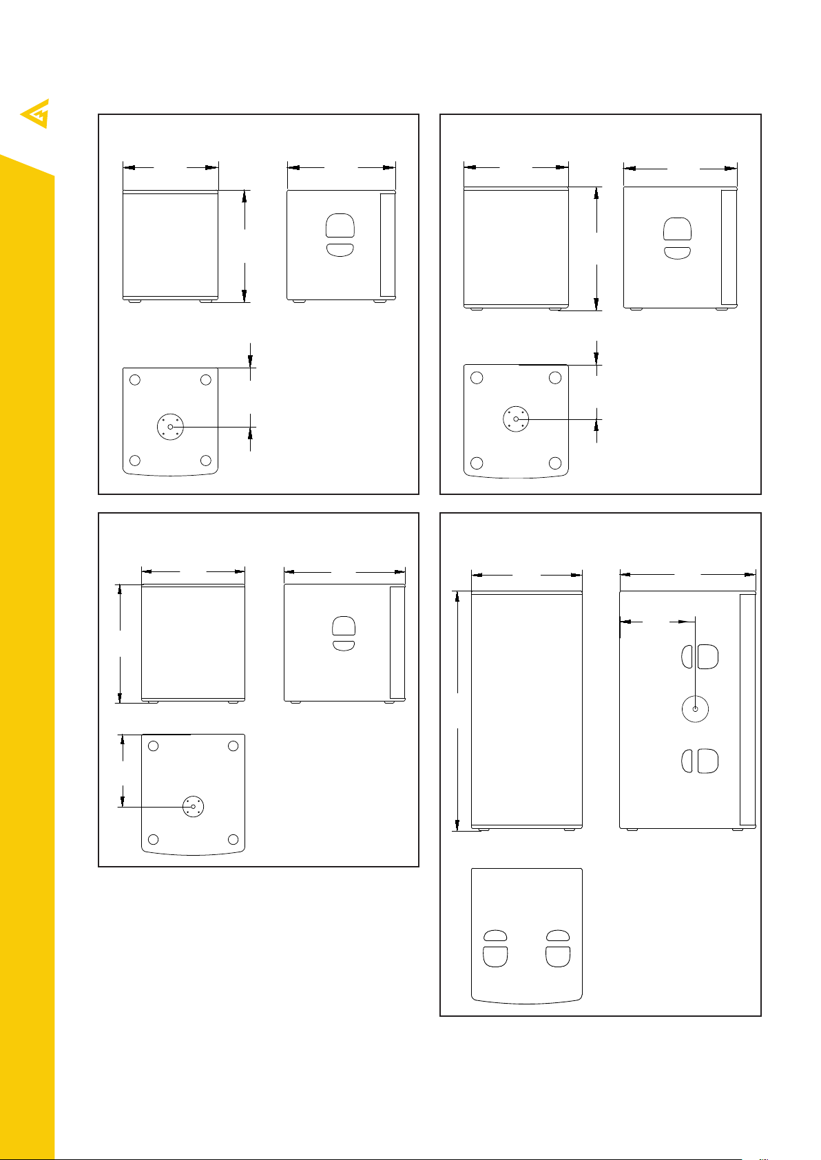
Panel A. Dimensions
390
443
440
479
530
610
621
460
242
Sub 12
Sub 12A
Sub 18
Sub 28A
Sub 15
Sub 15A
522
229
Sub 18
Sub 28A
Tel./Fax: +38 044 277-47-89 www.mag-audio.com
371
1150
530
651
358
4
SUBWOOFER Series User Manual rev 1.00
Page 5
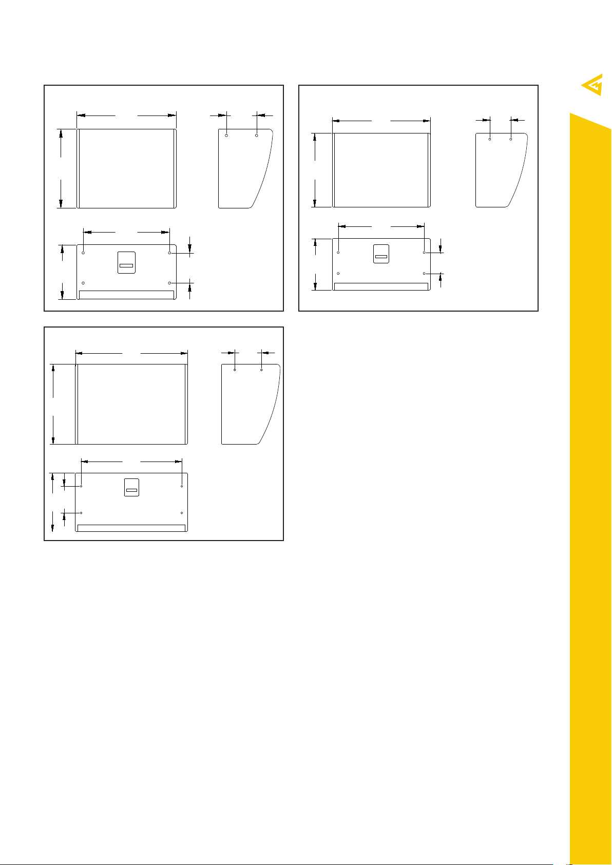
Sub 12i
610
185
486
335
700
150
370
527
840
200
600
440
Sub 15i
200
530
754
185
614
150
Sub 18i
SUBWOOFER Series User Manual rev 1.00
Tel./Fax: +38 044 277-47-89 www.mag-audio.com
5
Page 6
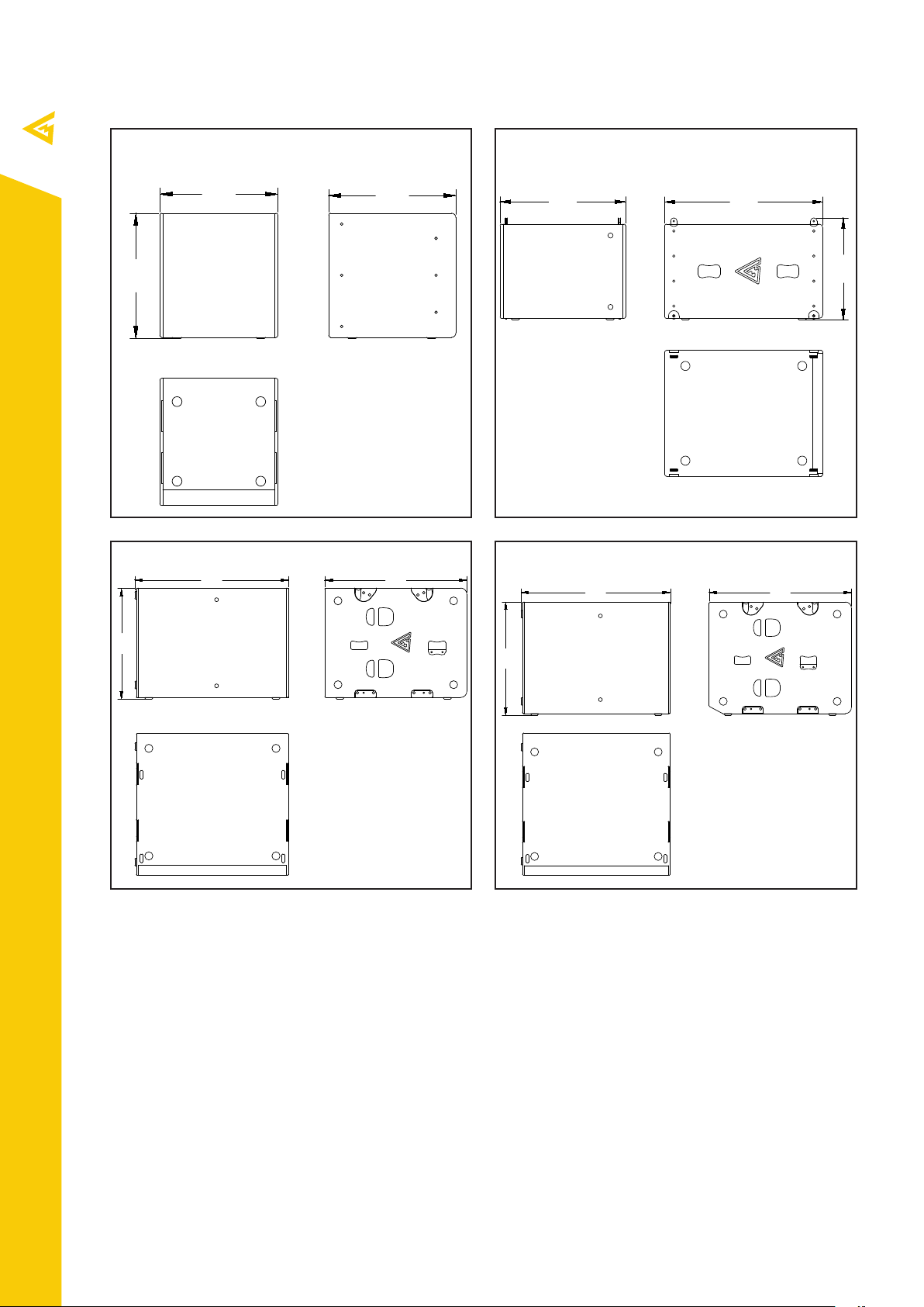
Sub C15
480
508
517
492
765
608
984
710
910
984
744
938
Sub H12
Sub H25 Sub H28
Tel./Fax: +38 044 277-47-89 www.mag-audio.com
6
SUBWOOFER Series User Manual rev 1.00
Page 7
1. Safety instructions
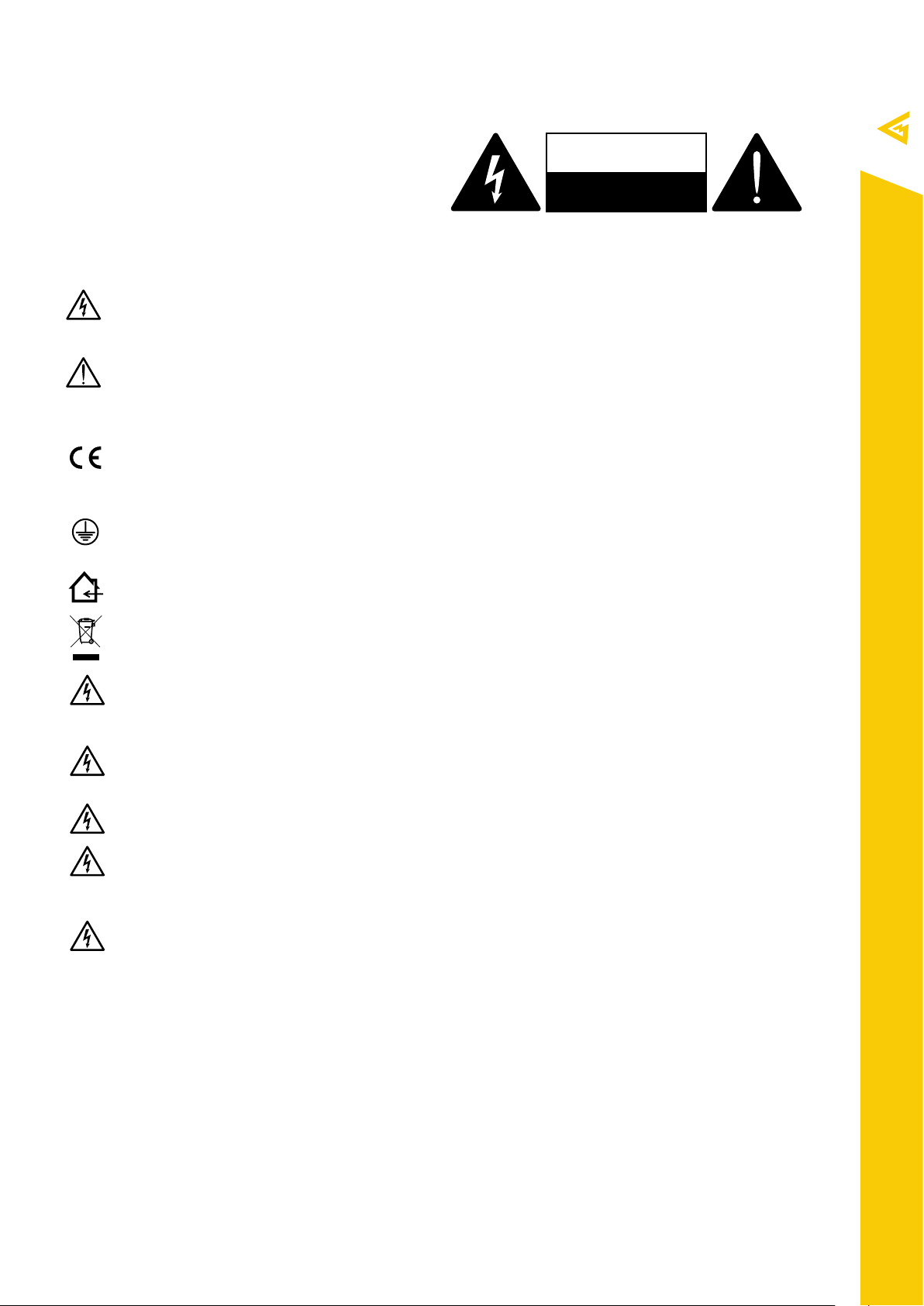
CAUTION
RISK OF ELECTRIC SHOCK
= =
DO NOT OPEN
=
EXPLANATIONS OF GRAPHICAL SYMBOLS
The triangle with the lightning bolt is used to alert the
user to the risk of electric shock.
The triangle with the exclamation point is used to
alert the user to important operating or maintenance
instructions.
The CE-mark indicates the compliance with the low
voltage and electromagnetic compatibility.
Symbol for earth/ground connection.
Symbol indicating that the equipment is for indoor use
only.
Symbol for conformity with Directive 2002/96/EC and
Directive 2003/108/EC of the European Parliament on
waste electrical and electronic equipment (WEEE).
WARNING: TO REDUCE THE RISK OF ELECTRIC SHOCK,
DO NOT ATTEMPT TO OPEN ANY PART OF THE
UNIT. NO USER-SERVICEABLE PARTS INSIDE. REFER
SERVICING TO QUALIFIED SERVICE PERSONNEL.
TO COMPLETELY DISCONNECT THIS APPARATUS
FROM THE AC MAINS, DISCONNECT THE POWER
SUPPLY CORD PLUG FROM THE AC RECEPTACLE.
THE MAINS PLUG OF THE POWER SUPPLY CORD
MUST REMAIN READILY ACCESSIBLE.
DO NOT EXPOSE THIS EQUIPMENT TO RAIN OR
MOISTURE, DRIPPING OR SPLASHING LIQUIDS.
OBJECTS FILLED WITH LIQUIDS, SUCH AS VASES,
SHOULD NOT BE PLACED ON THIS APPARATUS.
CONNECTIONS TO THE MAINS SHALL BE DONE ONLY
BY AN ELECTROTECHNICALLY SKILLED PERSON
ACCORDING TO THE NATIONAL REQUIREMENTS OF
THE COUNTRIES WHERE THE UNIT IS SOLD.
IMPORTANT SAFETY INSTRUCTIONS
1. Read these instructions carefully.
2. Keep these instructions.
3. Heed all warnings.
4. Follow all instructions.
5. Do not use this equipment near water.
6. Clean only with dry cloth.
7. Do not block any ventilation openings. Install in accordance
with the manufacturer’s instructions.
8. Do not use near heat sources such as stoves, heat registers,
radiators or other equipment (including amplifiers) that produces
heat.
9. Do not use the unit near open fire sources.
10. Connect the unit only to the electric network with grounding.
Use only electic plugs that provide grounding.
11. Protect the power cord from being walked on, pinched, or
otherwise damaged.
12. Use only accessories specified by the manufacturer.
13. Unplug this unit during lightning storms or when unused for
long periods of time.
14. Refer all servicing to qualified service personnel. Servicing is
required when the system has been damaged in any way, such
as power supply cord or plug is damaged, liquid has been spilled
or objects have fallen into the unit, the unit has been exposed
to rain or moisture, does not operate normally, or has been
dropped.
15. WARNING: TO REDUCE THE RISK OF FIRE OR ELECTRIC
SHOCK, DO NOT EXPOSE THIS SYSTEM UNIT TO RAIN OR
MOISTURE.
THIS UNIT CONTAINS POTENTIALLY LETHAL VOLTAGES.
TO PREVENT ELECTRIC SHOCK OR HAZARD, DO NOT
REMOVE THE AMPLIFIER MODULE. NO USER SERVICEABLE
PARTS INSIDE. REFER SERVICING TO QUALIFIED SERVICE
PERSONNEL.
INSTALLING OF THIS UNIT MUST BE PERFORMED ONLY BY
QUALIFIED TRAINED PERSONNEL FOLLOWING APPLICABLE
SAFETY RULES. DO NOT ALLOW INSTALLATION OF THIS UNIT
IF INSTALLATION HARDWARE IS BROKEN, BENT, PARTS ARE
MISSING OR IS OTHERWISE DAMAGED.
Tel./Fax: +38 044 277-47-89 www.mag-audio.com
SUBWOOFER Series User Manual rev 1.00
7
Page 8

2. Regulatory information
FCC COMPLIANCE NOTICE
This device complies with part 15 of the FCC
rules. Operation is subject to the following two
conditions: (1) This device may not cause harmful
interference, and (2) this device must accept any
interference received, including interference that
may cause undesired operation.
CAUTION: Changes or modifications not expressly
approved by the party responsible for compliance
could void the user’s authority to operate the
equipment.
NOTE: This equipment has been tested and found
to comply with the limits for a Class B digital device,
pursuant to part 15 of the FCC Rules. These limits are
designed to provide reasonable protection against
harmful interference in a residential installation. This
equipment generates, uses, and can radiate radio
frequency energy and, if not installed and used in
accordance with the instruction manual, may cause
harmful interference to radio communications.
However, there is no guarantee that interference
will not occur in a particular installation. If this
equipment does cause harmful interference to radio
or television reception, which can be determined
by turning the equipment o and on, the user is
encouraged to try to correct the interference by
one or more of the following measures:
- Reorient or relocate the receiving antenna.
- Increase the distance between the equipment
and receiver.
- Connect the equipment to an outlet on a
circuit dierent from that to which the receiver is
connected.
- Consult the dealer or an experienced radio/TV
technician for help.
EC DECLARATION OF CONFORMITY
Manufacturer:
MAG Audio LLC
Merezhna 2
Bila Tserkva, Kyiv region
09112 Ukraine
We declare that under our sole responsibility the
products:
Model Names:
Sub 12-4, Sub 12-8,
Sub 15-4, Sub 15-8,
Sub 18-4, Sub 18-8,
Sub 28, Sub 12A, Sub 15A,
Sub 18A, Sub 28,
Sub 12i-4, Sub 12i-8,
Sub 15i-4, Sub 15i-8,
Sub 18i-4, Sub 18i-8,
Sub C15, Sub H12,
Sub H25, Sub H28
Intended use: Professional Speaker System
Are in conformity with the provisions of the
following EC Directives, including all amendments,
and with the national legislation implementing
these directives:
- 2006/95/EC Low Voltage Directive
- 2004/108/EC Electromagnetic Compatibility Directive
- 2002/95/CE RoHs Directive
The following harmonized standards are applied:
EN 55103-1:2009 /A1:2012
EN 55014-1:2006 /A1:2009 /A2:2011
EN 55022:2010 /AC:2011
EN 61000-3-2:2006 /A1:2009 /A2: 2009
EN 61000-3-3:2013
EN 61000-3-11:2000
EN 61000-3-12:2011
EN 55103-2:2009 /IS:2012
EN 61000-4-2:2009
EN 61000-4-3:2006 /A1:2008 /IS1:2009 /A2:2010
EN 61000-4-4:2012
EN 61000-4-5:2006
EN 61000-4-6:2014
EN 61000-4-11:2004
EN 60065:2002 /A1:2006 /A11:2008 /A2:2010 /A12:2011
Tel./Fax: +38 044 277-47-89 www.mag-audio.com
8
Bila Tserkva,
22 January 2019
Alexey Asanov
CEO
For compliance questions: [email protected]
SUBWOOFER Series User Manual rev 1.00
Page 9

3. SUBWOOFER series
3.1 Introduction
Subwoofer series serves as an ultimate low
frequency reinforcement range that represents
all-purpose solutions, capable to meet the specific
demands of any and all innovative projects.
Series includes conventional passive and powered
boxes for mobile and stationary use, installationready cabinets with several mounting possibilities
and weatherproof option, and special-purpose
subwoofers for low-frequency clusters in touring
and concert applications.
3.2 SUBWOOFER series speaker models
SUBWOOFER series includes following speaker
models:
Sub 12-4 part number 00-0004616
Sub 12-8 part number 00-0005856
Sub 15-4 part number 00-0005854
Sub 15-8 part number 00-0004613
Sub 18-4 part number 00-0005855
Sub 18-8 part number 00-0004478
Sub 28-4 part number 00-0004617
Sub 12A part number 00-0004615
Sub 15A part number 00-0004614
Sub 18A part number 00-0004328
Sub 28A part number 00-0004618
Sub 12i-4 part number 00-0006521
Sub 12i-8 part number 00-0004550
Sub 15i-4 part number 00-0006522
Sub 15i-8 part number 00-0004535
Sub 18i-4 part number 00-0006523
Sub 18i-8 part number 00-0004536
Sub C15 part number 00-0004611
Sub H12 part number 00-0003871
Sub H25 part number 00-0004612
Sub H28 part number 00-0004396
SUBWOOFER Series User Manual rev 1.00
Tel./Fax: +38 044 277-47-89 www.mag-audio.com
9
Page 10

4. Specifications
System
Sub 12
Passive subwoofer
Sub 15
Passive subwoofer
Sub 18
Passive subwoofer
Sub 28
Passive subwoofer
Frequency Response (−10dB) 45 - 300 Hz 37 - 300 Hz 33 - 300 Hz 30 - 220 Hz
Max SPL
1
130,5 dB 133 dB 138 dB 143 dB
Sensitivity (1W/1m) 95 dB 94 dB 98 dB 100 dB
LF Driver 12”, 3" VC 15”, 4” VC 18”, 4” VC 2x 18”, 4” VC
Impedance
Nominal power
4 Ohm (Sub 12-4)
8 Ohm (Sub 12-8)
2
450 W 1000 W 1300 W 2600 W
4 Ohm (Sub 15-4)
8 Ohm (Sub 15-8)
4 Ohm (Sub 18-4)
8 Ohm (Sub 18-8)
4 Ohm
Connectors 2x Neutrik Speakon 2x Neutrik Speakon 2x Neutrik Speakon 2x Neutrik Speakon
Dimensions (W×H×D), mm 390x463x443 mm 440x523x479 mm 530x613x621 mm 530x1153x651 mm
Net weight, kg 29 kg 37 kg 42 kg 78 kg
Shipping weight, kg 32 kg 40 kg 45 kg 81 kg
Mounting
Enclosure material
Grill
1
- peak value, calculated according to AES 2 - 2012
2
- based on transducer power measured according to AES 2 - 2012
M20 distance pole
adapter
Plywood; wear-
resistant paint
Steel grill, acoustically
transparent foam
M20 distance pole
adapter
Plywood; wear-
resistant paint
Steel grill, acoustically
transparent foam
M20 distance pole
adapter
Plywood; wear-
resistant paint
Steel grill, acoustically
transparent foam
Two M20 distance
pole adapters
Plywood; wear-
resistant paint
Steel grill, acoustically
transparent foam
Tel./Fax: +38 044 277-47-89 www.mag-audio.com
System
Sub 12i
Installation subwoofer
Sub 15i
Installation subwoofer
Sub 18i
Installation subwoofer
Frequency Response (−10dB) 45 - 300 Hz 37 - 300 Hz 33 - 300 Hz
Max SPL
1
130,5 dB 133 dB 138 dB
Sensitivity (1W/1m) 95 dB 94 dB 98 dB
LF Driver 12”, 3" VC 15”, 4” VC 18”, 4” VC
Impedance
Nominal power
4 Ohm (Sub 12i-4)
8 Ohm (Sub 12i-8)
2
450 W 1000 W 1300 W
4 Ohm (Sub 15i-4)
8 Ohm (Sub 15i-8)
4 Ohm (Sub 18-4)
8 Ohm (Sub 18-8)
Connectors Barrier strip Barrier strip Barrier strip
Dimensions (W×H×D), mm 616x486x335 mm 700x527x370 mm 840x600x440 mm
Net weight, kg 29 kg 36 kg 50 kg
Shipping weight, kg 33 kg 41 kg 55 kg
Mounting
Enclosure material
Grill
1
- peak value, calculated according to AES 2 - 2012
2
- based on transducer power measured according to AES 2 - 2012
10x M10 mounting point;
VESA 200x200
Plywood; wear-resistant
paint
Steel grill, acoustically
transparent foam
10x M10 mounting point;
VESA 200x200
Plywood; wear-resistant
paint
Steel grill, acoustically
transparent foam
10x M10 mounting point;
VESA 200x200
Plywood; wear-resistant
paint
Steel grill, acoustically
transparent foam
10
SUBWOOFER Series User Manual rev 1.00
Page 11

System
Sub 12A
Powered subwoofer
Sub 15A
Powered subwoofer
Sub 18A
Powered subwoofer
Sub 28A
Powered subwoofer
Frequency Response (−10dB) 43 - 170 Hz 35 - 170 Hz 31 - 170 Hz 30 - 250 Hz
Max SPL (calculated) 127,5 dB 134 dB 138 dB 139,5 dB
LF Driver 12”, 3" VC 15”, 4” VC 18”, 4” VC 2x 18”, 4” VC
Amplifier power 650 W 2400 W 2400 W 3000 W
Amplifier
Class D, fan cooling,
DSP
Class D, fan cooling,
DSP
Class D, fan cooling,
DSP
Class D, fan cooling,
DSP
Input sensitivity 0 dBV (1 V RMS) 0 dBV (1 V RMS) 0 dBV (1 V RMS) 0 dBV (1 V RMS)
Connectors
XLR input, XLR
output, Powercon
mains
XLR input, XLR
output, Powercon
mains
XLR input, XLR
output, Powercon
mains
XLR input, XLR
output, Powercon
mains
Dimensions (W×H×D), mm 390x463x443 mm 440x523x479 mm 530x613x621 mm 530x1153x651 mm
Net weight, kg 32 kg 40 kg 45 kg 81 kg
Shipping weight, kg 35 kg 43 kg 48 kg 84 kg
Mounting
Enclosure material
Grill
M20 distance pole
adapter
Plywood; wear-
resistant paint
Steel grill, acoustically
transparent foam
M20 distance pole
adapter
Plywood; wear-
resistant paint
Steel grill, acoustically
transparent foam
M20 distance pole
adapter
Plywood; wear-
resistant paint
Steel grill, acoustically
transparent foam
Two M20 distance
pole adapters
Plywood; wear-
resistant paint
Steel grill, acoustically
transparent foam
System
Sub C15
Passive arrayable
subwoofer
Sub H12
Passive arrayable
subwoofer
Sub H25
Passive hybrid-horn
subwoofer
Sub H28
Passive hybrid-horn
subwoofer
Frequency Response (−10dB) 37 - 300 Hz 42 - 140 Hz 37 - 120 Hz 28 - 120 Hz
Max SPL
1
133 dB 140 dB 146,5 dB 149,5 dB
Sensitivity (1W/1m) 94 dB 101 dB 105 dB 106 dB
LF Driver 15”, 4" VC 12”, 4” VC 2x 15”, 4” VC 2x 18”, 4,5” VC
Impedance 8 Ohm 8 Ohm 4 Ohm 4 Ohm
Nominal power
2
1000 W 950 W 1700 W 2900 W
Connectors Barrier strip 4x Neutrik Speakon 4x Neutrik Speakon 4x Neutrik Speakon
Dimensions (W×H×D), mm 456x509x513 mm 608x460x765 mm 700x980x900 mm 700x980x938 mm
Net weight, kg 38 kg 44,6 kg 92 kg 115 kg
Shipping weight, kg 41 kg 47,6 k g 96 kg 120 kg
Mounting
Enclosure material
Grill
1
- peak value, calculated according to AES 2 - 2012
2
- based on transducer power measured according to AES 2 - 2012
Integrated flying
hardware
Plywood; wear-
resistant paint
Steel grill, acoustically
transparent foam
Integrated flying
hardware
Plywood; wear-
resistant paint
Steel grill, acoustically
transparent foam
Integrated mounting
hardware
Plywood; wear-
resistant paint
Steel grill, acoustically
transparent foam
Integrated mounting
hardware
Plywood; wear-
resistant paint
Steel grill, acoustically
transparent foam
Tel./Fax: +38 044 277-47-89 www.mag-audio.com
SUBWOOFER Series User Manual rev 1.00
11
Page 12
5. System operation
5.1. Rigging
Several SUBWOOFER series systems are equipped with M10 mounting points for flown installation.
Rigging must be performed only by trained personnel following the established safety rules.
MAXIMUM WEIGHT RESTRICTIONS MUST BE FOLLOWED AT ALL TIMES!
MAKE SURE THE SUPPORT STRUCTURE IS CAPABLE OF HOLDING THE APPLIED WEIGHT WHILE
SUSPENDING THE SYSTEM!
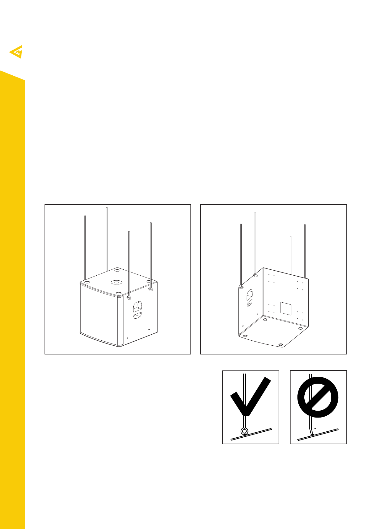
5.2. Flying Sub 15 or Sub 18 with M10 mounting points
Required accessories:
VA-0016 (part No. 00-00003695)
Sub 15 and Sub 18 are fit with eight M10 mounting points, allowing for suspended mounting with M10
eyebolts.
Tel./Fax: +38 044 277-47-89 www.mag-audio.com
12
5.3. Eye-bolt orientation
While flying, applied force must be in the plane of the
VA-0016 eyebolt’s ring. It is prohibited to arrange the rig
in the way that force is at the angle from the eyebolt’s ring
plane.
Right Wrong
SUBWOOFER Series User Manual rev 1.00
Page 13
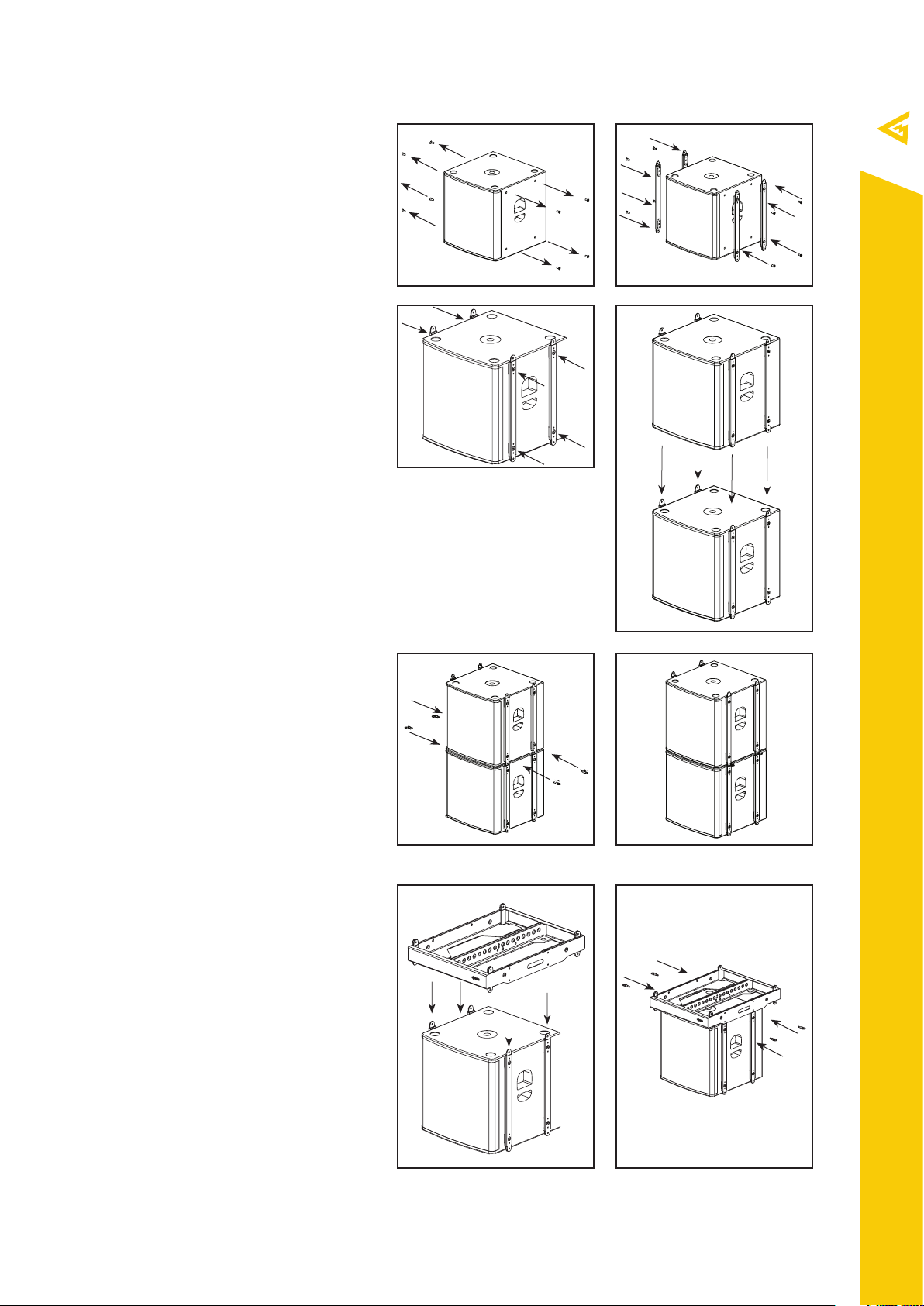
5.4. Flying a Sub 15 or Sub 18 stack
with array mount adapters
Accessories:
VA-0010 (part No. 00-00002878) - 4 pcs
AM-Sub-15 (part No. 00-0006742)
- 4 pcs or
AM-Sub-18 (part No. 00-0006741)
- 4 pcs
1. Remove 8 pcs of M10 mounting bolts for
cabinet’s mounting sockets (Pic 1).
2. Align 4 pcs of AM-Sub-15 (For Sub 15)
or 4 pcs of AM-Sub-18 (For Sub 18) array
mounts with M10 mounting sockets of the
cabinet (Pic 2).
3. Use 8 pcs of M10 mounting bolts to
secure array mounts onto the cabinets
(Pic 3).
4. Align a pair of Sub 15 or a pair of Sub 18
cabinets with array mounts attached. Insert
array mounts’ links into corresponding
sockets (Pic 4).
1
3
2
5. Secure connection with 4 pcs of
VA-0010 8mm pins (Pic 5, 6).
6. Attach additional cabinets if necessary
NO MORE THAN 4 PCS OF SUB 15 OR SUB
18 CABINETS MAY BE FLOWN WITH AMSUB-15 OR AM-SUB-18 ARRAY MOUNTS.
5.5. Flying a Sub 15 or Sub 18 stack
via flying frame
Required accessories:
VA-0010 (Part No. 00-00002878) - 4 pcs
WSF-01 (Part No. 00-0004068) - 1 pcs
1. Assemble a stack of Sub 15 or Sub 18 as
per paragraph 5.4.
2. Align the upper subwoofer with WSF-01
flying frame. Array mounts’ link should fit
into the frame’s sockets. (Pic. 1).
5 6
4
Tel./Fax: +38 044 277-47-89 www.mag-audio.com
3. Secure connection with four VA-0010
pins. (Pic. 2).
SUBWOOFER Series User Manual rev 1.00
1 2
13
Page 14

5.6. Wall mounting of Sub 12i, Sub
15i and Sub 18i
Accessories:
LLS (part No. 00-00002647) - 1 pcs
1. Attach the mounting plate of the LLS
mounting bracket to the wall using fixing
holes provided (Pic 1).
2. Attach two mounting planks of the
LLS mounting bracket to VESA 200x200
mounting holes of the cabinet using M6
bolts. (Pic 2).
3. Hang the cabinet with attached mounting
planks onto the mounting plate (Pic 3, 4).
4. Use a hex key to secure the mounting
bracket by tightening two M6 on the
bottom of the LLS (Pic 5, 6).
1
3
2
4
Tel./Fax: +38 044 277-47-89 www.mag-audio.com
14
5 6
SUBWOOFER Series User Manual rev 1.00
Page 15
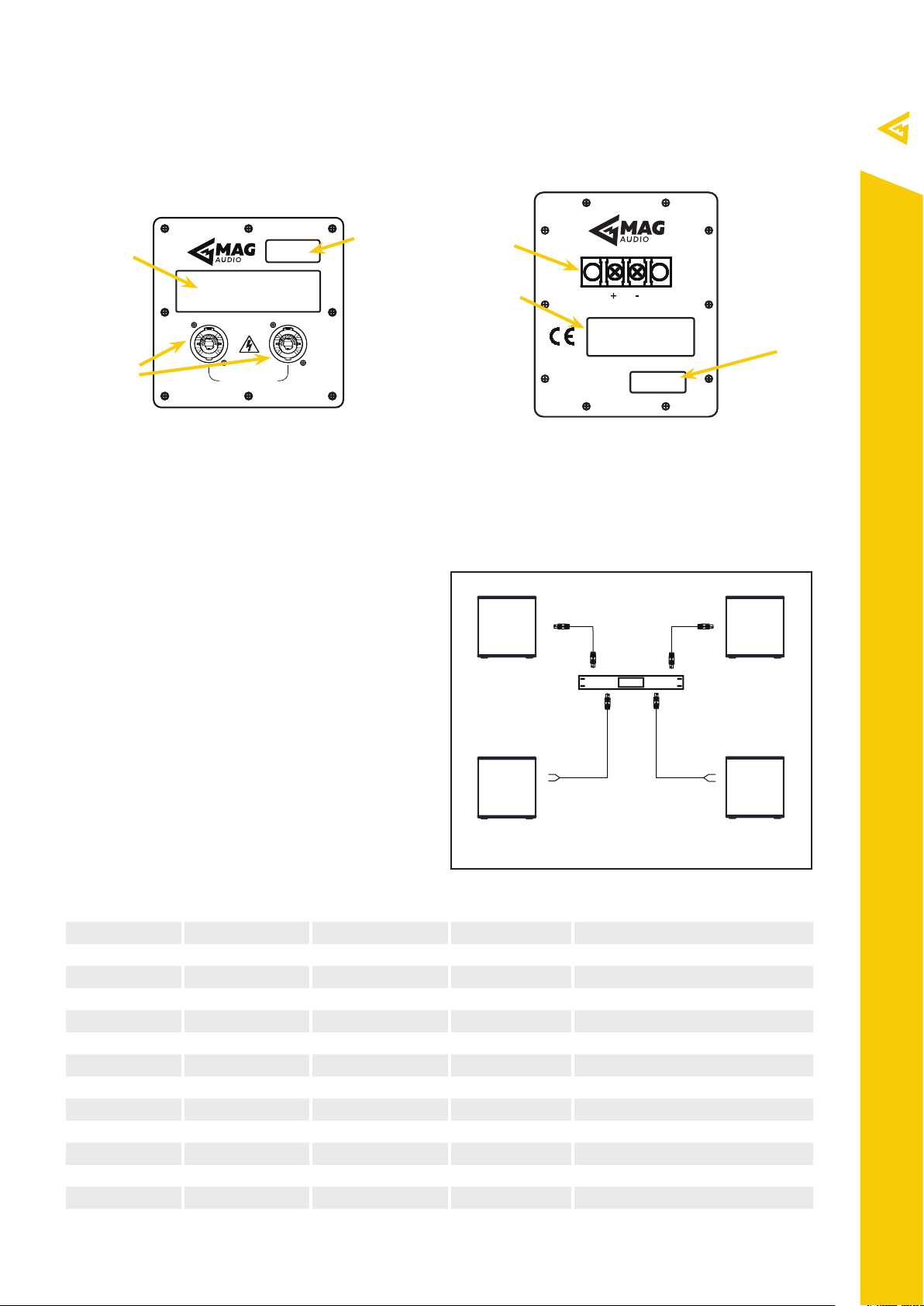
5.7. Passive speakers
Sub 12, Sub 15, Sub 18, Sub 28, Sub
C15, Sub H12, Sub H25, Sub H28
connection plate
2
1
3
Made in Ukraine by Magnet Ltd.
1. LABEL FIELD. Name of the system, along with its basic
parameters is noted here.
2. SERIAL NUMBER FIELD. Sticker with the systems serial
number is located here. NEVER REMOVE THE SERIAL FROM
THE SYSTEM, AS IT IS IMMEDIATE WARRANTY VOID.
5.7.1. Passive connections
Suggested accessories:
CN-0031 (part No. 00-00004271)
CN-0032 (part No. 00-00004272)
PARALLEL INPUTS
www.mag-audio.com
Sub 12i, Sub 15i, Sub 18i
connection plate
4
1
INPUT
2
Made in Ukraine
www.mag-audio.com
3. PARALLEL INPUTS. The pair of parallel Neutrik® Speakon
connectors. Use this connectors to connect power amplifier and
to feed the signal to the parallel system (optional).
4. INPUT. Pair of screw terminals. Use these to connect power
amplifier.
SUBWOOFER series passive connection diagram
Speakon-Speakon
cable
Speakon-Speakon
cable
Use power amplifier with DSP or power amplifiers
with external speaker processor with SUBWOOFER
SUBWOOFER series
passive system
DSP AMPLIFIER
series passive systems.
MAKE SURE TO USE HIGH PASS FILTER FOR
ALL SUBWOOFER SERIES SYSTEMS TO
PREVENT EXCESSIVE CONE MOVEMENT,
RESULTING IN TRANSDUCER DAMAGE OR FAST
DETERIORATION.
Recommended HPF settings, suggested power
amplifier ratings, and connection pins are found in
SUBWOOFER i series
passive system
Speakon-2 wire
cable
Speakon-2 wire
cable
table below:
System Amplifier power Amplifier impedance Connection pins Recommended HPF
Sub 12-4 450 - 900 W 4 Ohm +1 -1 40 Hz or higher, 18 dB/oct min
Sub 12-8 450 - 900 W 8 Ohm +1 -1 40 Hz or higher, 18 dB/oct min
Sub 15-4 1000 - 2000 W 4 Ohm +1 -1 35 Hz or higher, 18 dB/oct min
Sub 15-8 1000 - 2000 W 8 Ohm +1 -1 35 Hz or higher, 18 dB/oct min
Sub 18-4 1300 - 2600 W 4 Ohm +1 -1 30 Hz or higher, 18 dB/oct min
Sub 18-8 1300 - 2600 W 8 Ohm +1 -1 30 Hz or higher, 18 dB/oct min
Sub 28-4 2600 - 5200 W 4 Ohm +1 -1 27 Hz or higher, 18 dB/oct min
Sub 12i-4 450 - 900 W 8 Ohm +1 -1 40 Hz or higher, 18 dB/oct min
Sub 12i-8 450 - 900 W 4 Ohm +1 -1 40 Hz or higher, 18 dB/oct min
Sub 15i-4 1000 - 2000 W 8 Ohm +1 -1 35 Hz or higher, 18 dB/oct min
Sub 15i-8 1000 - 2000 W 4 Ohm +1 -1 35 Hz or higher, 18 dB/oct min
Sub 18i-4 1300 - 2600 W 8 Ohm +1 -1 30 Hz or higher, 18 dB/oct min
Sub 18i-8 1300 - 2600 W 4 Ohm +1 -1 30 Hz or higher, 18 dB/oct min
SUBWOOFER series
passive system
SUBWOOFER i series
passive system
Tel./Fax: +38 044 277-47-89 www.mag-audio.com
15
SUBWOOFER Series User Manual rev 1.00
Page 16

System Amplifier power Amplifier impedance Connection pins Recommended HPF
Sub C15-8 1000 - 2000 W 8 Ohm +1 -1 35 Hz or higher, 18 dB/oct min
Sub H12 Link Front +1 -1 35 Hz or higher, 18 dB/oct min
Sub H12 950 - 1900 W 8 Ohm Front +2 -2 35 Hz or higher, 18 dB/oct min
Sub H12 950 - 1900 W 8 Ohm Rear +1 -1 35 Hz or higher, 18 dB/oct min
Sub H12 Link Rear +2 -2 35 Hz or higher, 18 dB/oct min
Sub H25 Link Front +1 -1 35 Hz or higher, 18 dB/oct min
Sub H25 1700 - 3400 W 4 Ohm Front +2 -2 35 Hz or higher, 18 dB/oct min
Sub H25 1700 - 3400 W 4 Ohm Rear +1 -1 35 Hz or higher, 18 dB/oct min
Sub H25 Link Rear +2 -2 35 Hz or higher, 18 dB/oct min
Sub H28 Link Front +1 -1 25 Hz or higher, 18 dB/oct min
Sub H28 2900 - 5800 W 4 Ohm Front +2 -2 25 Hz or higher, 18 dB/oct min
Sub H28 2900 - 5800 W 4 Ohm Rear +1 -1 25 Hz or higher, 18 dB/oct min
Sub H28 Link Rear +2 -2 25 Hz or higher, 18 dB/oct min
Tel./Fax: +38 044 277-47-89 www.mag-audio.com
16
SUBWOOFER Series User Manual rev 1.00
Page 17
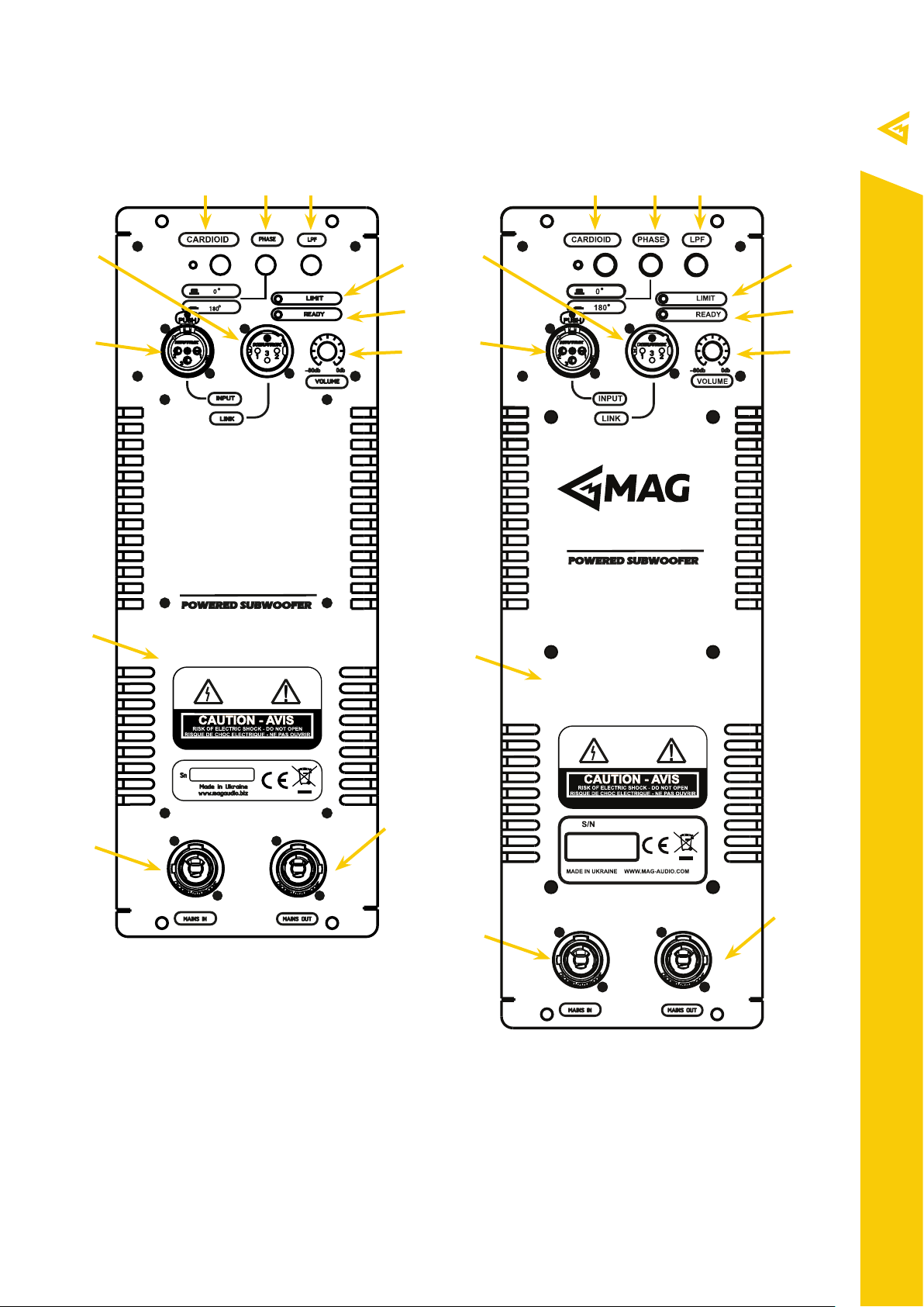
5.8. Powered speakers
Sub 12A amplifier Sub 15A, Sub 18A amplifier
12
11
8 9 10
0
°
180
°
5
6
8 9 10
12
7
11
6
7
5
13
15
14
5. VOLUME KNOB. Used for adjusting the volume of the
system. Remember to turn the volume down before connecting/
disconnecting INPUT or LINK connectors.
6. LIMIT LED. Is lit when limiter is operational, indicating excessive
signal through the system.
7. READY LED. Is lit when system is fully operational.
8. CARDIOID BUTTON. Engaged on reversed subwoofer, creates
a cardioid coverage of a subwoofer array.
13
15
14
10. LPF BUTTON. Engages a 100 Hz Low pass filter.
11. INPUT CONNECTOR. Used for connecting the system to the
signal source (mixing console etc.)
12. LINK CONNECTOR. Used for linking additional compactible
system to the same signal source.
13. HEAT SINK. Do not close the ventilation openings on the heat
sink, as it may cause the system to overheat and switch o by
itself.
Tel./Fax: +38 044 277-47-89 www.mag-audio.com
9. PHASE BUTTON. Switches the polarity.
17
SUBWOOFER Series User Manual rev 1.00
Page 18

Sub 28A amplifier
1319 18
6
16
17
7
11
12
13
LIMIT
TEMP
SIGNAL
READY
PRESET
SELECT
PRESET1
PRESET2
PRESET3
PRESET4
Tel./Fax: +38 044 277-47-89 www.mag-audio.com
18
15
14
14. MAINS IN. Used for connecting mains supply to the system.
15. MAINS OUT. Used for feeding the mains supply to the
additional system.
16. TEMP LED. Is flashing when amplifier is at the possibility of
overheating. Is lit when thermal shutdown is engaged.
17. SIGNAL LED. Indicated if the signal is present at the module’s
input.
18. PRESET LEDS. Shows currently used preset.
19. PRESET SELECT BUTTON. Switches currently selected
preset.
SUBWOOFER Series User Manual rev 1.00
Page 19

5.8.1. Mains connection.
SUBWOOFER series powered systems are supplied with CN-0010 PowerCon-E/F CEE 7/7 mains cable
(part number 00-00005561). Use only original or supplied by manufacturer mains cables!
SUBWOOFER series powered systems are equipped with PowerCon B mains power outlets for mains link
to additional SUBWOOFER series powered system.
SUBWOOFER series systems’ nominal mains power specifications: AC 220V, 50/60 Hz.
Nominal voltage tolerance: 100 - 250 V.
To power up the system, connect the mains cable to the system, then to the power outlet.
To completely power down the system, disconnect the mains cable from the power outlet.
5.8.2. Signal connections.
SUBWOOFER series systems are equipped with XLR INPUT an XLR LINK connectors for signal connection.
Use of balanced XLR connector cables is recommended. In case when balanced XLR connections are not
available, unbalanced XLR connection is acceptable.
For linking the additional system to the same signal bus LINK connector may be used.
2
3
1
Plus (+)
Minus (-)
Shield (Ground)
Balanced XLR Plug connections
Amplifier controls. Use several available
SUBWOOFER series speaker system’s amplifier
controls to set up the entire system:
LPF 100Hz: Provides a 100Hz low-pass filter to
seamlessly couple a powered subwoofer with fullrange systems.
PHASE: Switches the polarity of the subwoofer for
better coupling with the rest of the sound system.
CARDIOID: Enables the inversed subwoofer mode,
allowing creation of subwoofer arrays with cardioid
coverage.
5.8.3. Sub 28A presets.
Powered Sub 28A subwoofer is fit with four presets
for choosing the best performance in dierent
situations:
2
3
1
Plus (+)
Shield (Ground)
Shield (Ground)
Unbalanced XLR Plug connections
XLR-XLR cable XLR-XLR cable
SUBWOOFER
series powered
system
XLR-XLR cable XLR-XLR cable
SUBWOOFER
series powered
system
To signal source
SUBWOOFER series powered signal connection diagram
SUBWOOFER
series powered
system
SUBWOOFER
series powered
system
- PRESET 1: MAIN. Primary preset with HPF and
LPF filters.
- PRESET 2: MAIN 180: Primary preset with HPF
and LPF, phase switched 180 degrees.
- PRESET 3: CARDIOID: Used on inverted subwoofer
to create cardioid low-frequency arrays.
- PRESET 4: MAIN NO LPF: Primary preset with
HPF only. LPF is o for use with external processing.
SUBWOOFER Series User Manual rev 1.00
Tel./Fax: +38 044 277-47-89 www.mag-audio.com
19
Page 20

6. Standard contents
Please check the complement of your SUBWOOFER series system upon receiving the package.
Standard contents of SUBWOOFER series systems:
System Supplied SUBWOOFER series system
Sub 12-4 Sub 12 4 Ohm passive system + + +
Sub 12-8 Sub 12 8 Ohm passive system + + +
Sub 15-4 Sub 15 4 Ohm passive system + + +
Sub 15-8 Sub 15 8 Ohm passive system + + +
Sub 18-4 Sub 18 4 Ohm passive system + + +
Sub 18-8 Sub 18 8 Ohm passive system + + +
Sub 28-4 Sub 28 4 Ohm passive system + + +
Sub 12i-4 Sub 12i 4 Ohm passive system + + +
Sub 12i-8 Sub 12i 8 Ohm passive system + + +
Sub 15i-4 Sub 15i 4 Ohm passive system + + +
Sub 15i-8 Sub 15i 8 Ohm passive system + + +
Sub 18i-4 Sub 18i 4 Ohm passive system + + +
Sub 18i-8 Sub 18i 8 Ohm passive system + + +
Sub C15-8 Sub C15 8 Ohm passive system + + +
Sub H12-8 Sub H12 8 Ohm passive system + + +
Sub H25-4 Sub H25 4 Ohm passive system + + +
Sub H28-4 Sub H28 4 Ohm passive system + + +
Sub 12A Sub 12A powered system + + + +
Sub 15A Sub 15A powered system + + + +
Sub 18A Sub 18A powered system + + + +
Sub 28A Sub 28A powered system + + + +
SUBWOOFER
series user
manual
CN-0010
mains cord
Polyethylene
bag
Cardboard
box
Tel./Fax: +38 044 277-47-89 www.mag-audio.com
20
SUBWOOFER Series User Manual rev 1.00
Page 21

7. Accessories
Various accessories are available for SUBWOOFER series systems:
AM-Sub-15
array mount
Part No. 00-0006742
LLS
mounting bracket
Part No. 00-00002647
AM-Sub-18
array mount
Part No. 00-0006741
SUB12-TB - Sub 12 transportation bag Part No. 00-0006747
SUB12A-TB - Sub 12A transportation bag Part No. 00-0006746
SUB15-TB - Sub 15 transportation bag Part No. 00-0006749
SUB15A-TB - Sub 15A transportation bag Part No. 00-0006748
SUB18-TB - Sub 18 transportation bag Part No. 00-0006750
SUB18A-TB - Sub 18A transportation bag Part No. 00-0006696
SUB28-TB - Sub 28 transportation bag Part No. 00-0006751
SUB28A-TB - Sub 28A transportation bag Part No. 00-0006752
SUBH12-TB3 - transportation bag for three pcs of Sub H12 Part No. 00-00003736
SUBH28-TB - Sub H28 transportation bag Part No. 00-0006753
WSF-01 versatile
frame
Part No. 00-0004068
VA-0010 8mm pin
Part No. 00-00002878
SUBWOOFER Series User Manual rev 1.00
Tel./Fax: +38 044 277-47-89 www.mag-audio.com
21
Page 22

8. Warranty and assistance
8.1. Product warranty
1. By this warranty MAG Audio grants that all
equipment manufactured under the MAG Audio
trademark is free from defects in material,
components and factory workmanship under
the normal use and maintenance for the time as
specified below.
2. All warranty repairs and maintenance of MAG
Audio products shall be carried out at MAG Audio
production sites or by MAG Audio authorized
personnel at no cost for the product purchaser.
3. Warranty period for cone transducers, high
frequency drivers and crossovers, whether sold
separately or as a component of a speaker system,
is 60 months from the production date.
4. Warranty period for enclosures, grills, connection
plates and accessories, whether sold separately or
as a component of a speaker system, is 60 months
from the production date.
5. Warranty period for built-in power amplifiers,
whether sold separately or as a component of a
speaker system, is 36 months form the production
date.
8.2. Assistance
There are no user-serviceable parts in your
device. Refer servicing to qualified technical
personnel. In addition to in-house service
department, MAG Audio supports the chain of
distributors, authorized in repairs and service. If
your device needs repairing, contact your MAG
Audio dealer or distributor.
Occasionally, due to the nature of the failure, it
might be necessary to return defective products to
MAG Audio for repair. In this case, before shipping,
please kindly contact your MAG Audio distributor or
dealer, or MAG Audio directly. You will be provided
the RMA number code and detailed instructions
regarding your particular case. Please do not send
products without a prior authorization.
Thank you for your understanding, cooperation and
choice of MAG Audio products.
Tel./Fax: +38 044 277-47-89 www.mag-audio.com
6. Warranty repairs or maintenance will be
performed only if a) MAG Audio product was
purchased from an ocial MAG Audio distributor
/ dealer and b) warranty card with specified serial
number, production date, realization date, vendor’s
signature and stamp is presented.
7. Warranty shall not cover the following: damage
caused by accident, misuse or failure to follow
exploitation rules stated in technical manual;
repairs performed by non-authorized personnel;
mechanical damage caused by shipping accidents
and normal tear and wear.
8. Warranty shall not be applicable to any product
with defaced, removed, or modified serial number.
9. If your MAG Audio product needs repairing
or maintaining, contact your ocial MAG Audio
distributor / dealer. Please do not ship your MAG
Audio product without prior authorization.
22
SUBWOOFER Series User Manual rev 1.00
Page 23

SUBWOOFER Series User Manual rev 1.00
Tel./Fax: +38 044 277-47-89 www.mag-audio.com
23
Page 24

info@mag-audio.com
Tel./Fax: +38 044 277-47-89 www.mag-audio.com
2 Merezhna str., Bila Tserkva,
Kyiv region, 09100, Ukraine
Tel./Fax.: +38 044 2774789
e-mail: [email protected]
www.mag-audio.com
24
SUBWOOFER Series User Manual rev 1.00
 Loading...