

MAG SL100DC Series Installation Manual
App
e
g
y
g
A
(
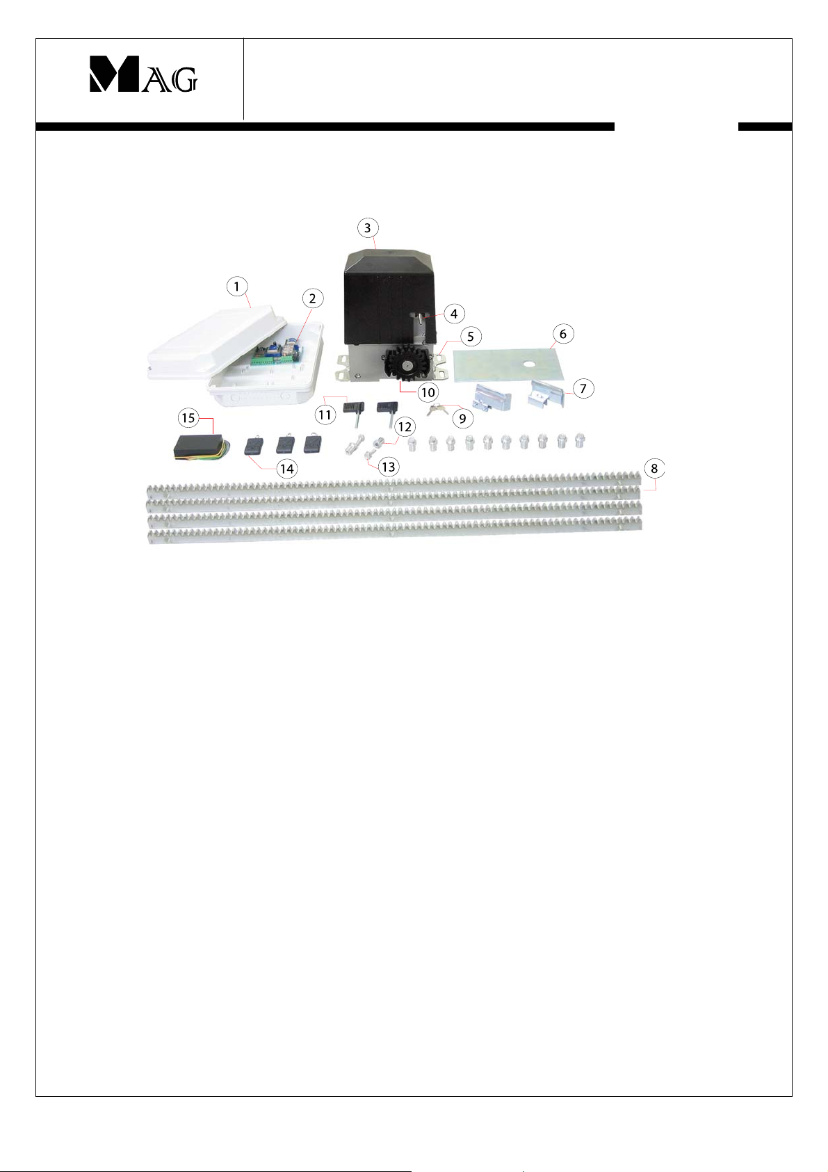
SL100DCx series – Sliding gate system
Gate Automatic System
MAG SL100ACx series is a complete sliding gate automation system.
Components in MAG SL100DCx series
1 PVC box
2 Control board
3 Motor
4 Limit switch
5 Mountin
6 Base plate
7 Limit switch stopper
8 Gear rack
bracket
Preliminary check
To ensure trouble-free operation, make sure that the gate (whether existing or yet to be installed) has the following
specification:
• Max gate weight 600kg
• Strong and rigid leaf frame
• Flat leaf face, with no protruding parts and no vertical members
• Straight, smooth and even movement of the least over its entire travel
• No sideway oscillation of the leaf
• Upper and lower sliding system in perfect condition
• The use of floor tracking with a rounded channel is preferred because it reduces friction in the sliding
movement
• Only two slide wheel
If any welding or brazing is required on the gate, it should be done before installing the automation system. The
condition of the gate structure will have direct affect on the reliability and safety of the automation system. We are
ready to install SL100P after making sure all the above items are checked.
Installation guide
9Ke
10 Pinion
11
12 Spacer
13 Bolt
14 Remote control transmitter
15 Remote control receiver
to unlock clutch
lan key to release clutch
lication not
ear
with screw tread)
© Install_CelmerSL100P - All specification and suggested dimension is for reference only- subject to change without further notice.
1
Door
Door
frame
g
Suggested installation steps include the following:
1. Doing the wiring groundwork at installation site
2. Installation of the operator motor
3. Installing control panel to the pillar wall
4. Installation of gear rack to gate
5. Mounting the limit switch stopper to the gear rack
6. Remove 4 extra washers from the motor operator
7. Testing and verifying wiring
** Step 2 and 3 might be interchanged while waiting for the cement base to dry. Special chemical can be added to the
cement base to shorten the dry time.
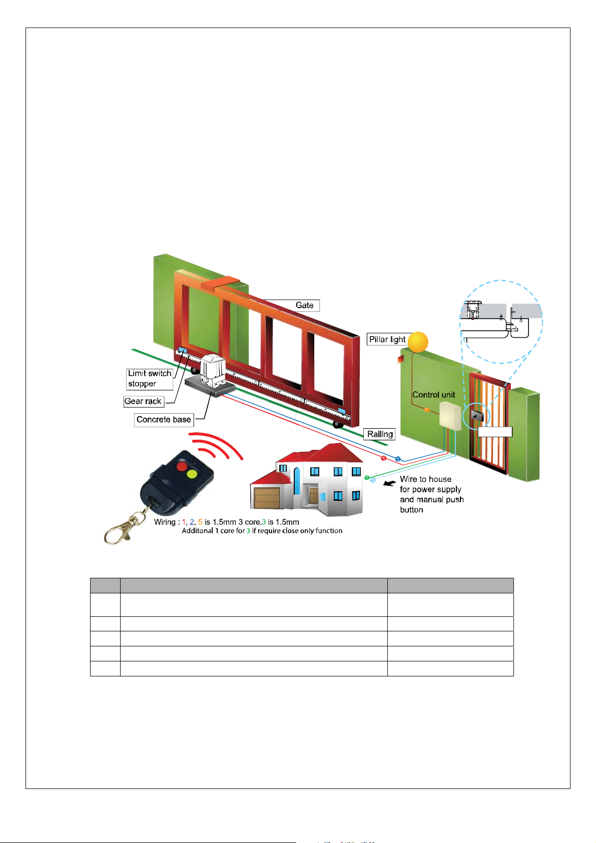
Standard installation layout
The below typical layout can be used to plan wiring groundwork at actual installation site. Use suitable rigid and/or
flexible pipes for laying power cables. Always keep low voltage accessory cables separated from 230V power cables.
To avoid interference, use separate sheaths. It is suggested to use the following recommended cable specification.
Lock remain secured
during power failure
- weatherproof
5
Wiring :1,2,5is 1.5mm 3 core.3is1.5mm 2core.4 is 2.5mm3 core.
Description Wire specification
1
Connectin
(Close, common and open)
limit switch signal from motor to control unit.
3 core, 1.5 mm diameter
2 AC230V power supply from control unit to the motor 3 core, 1.5 mm diameter
3 In door push button for manual control of the gate. 2 core, 1.5 mm diameter
4 AC230V power supply to the control unit 3 core, 2.5 mm diameter
5 Pillar light power supply 3 core, 1.5 mm diameter
© Install_CelmerSL100P - All specification and suggested dimension is for reference only- subject to change without further notice.
Rimlock
2
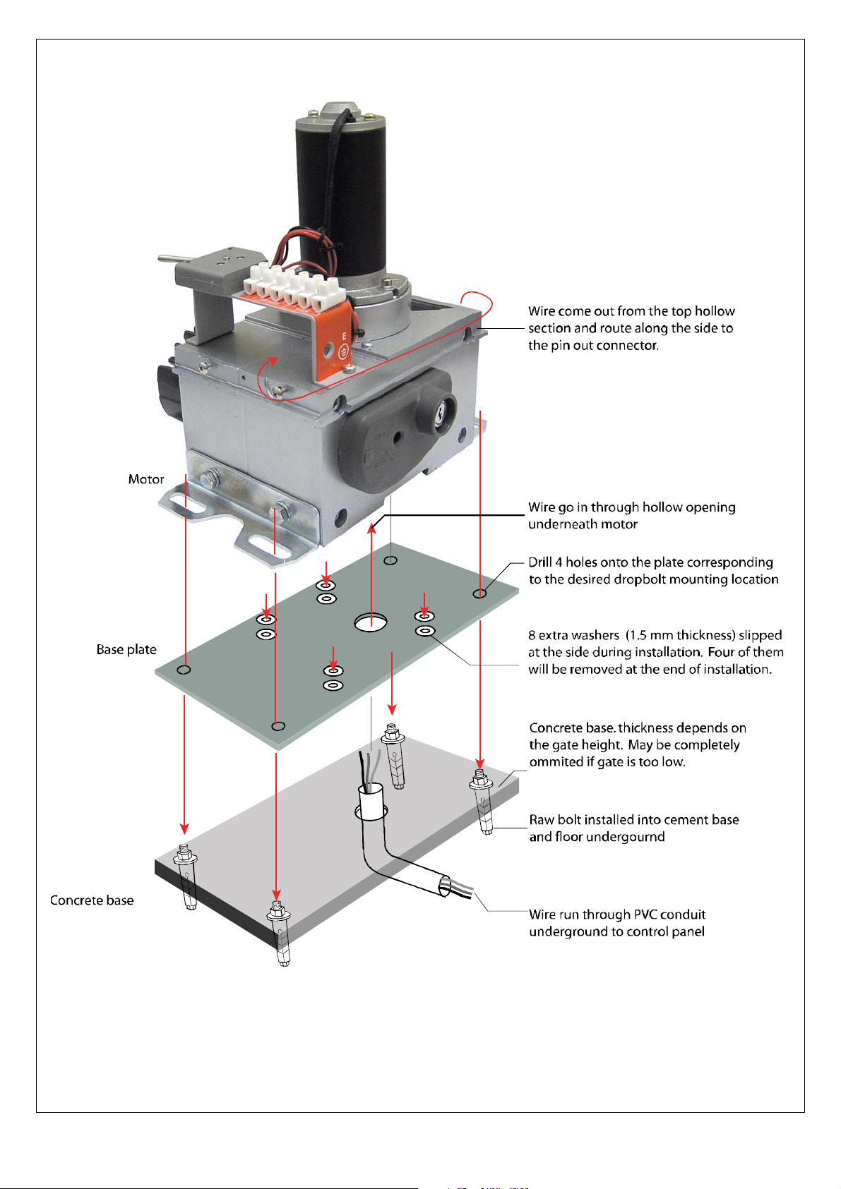
Installing the motor operator
© Install_CelmerSL100P - All specification and suggested dimension is for reference only- subject to change without further notice.
3
 Loading...