

1
info@mag-audio.com
Tel./Fax: +38 044 277-47-89 www.mag-audio.com
Fly Array User Manual rev 0.1
User Manual
Systems:
Fly 6
Fly Sub 12
Fly Sub 15
Fly Sub 18
FLY ARRAY

2
Fly Array User Manual rev 0.1
info@mag-audio.com
Tel./Fax: +38 044 277-47-89 www.mag-audio.com
Contents ....................................................................................................... 2
1. Safety instructions ...................................................................................... 3
2. System description ...................................................................................... 4
3.1. Specifications - Technical data ..................................................... 5
3.2. Specifications - Dimensions ................................................................... 6
4.1. System operation - Rigging ..................................................... 7
4.2 System operation - Amplifiers ..................................................... 11
4.3. System operation - Connections and setup ................... 12
4.4. System operation - Configurations .................................... 13
5. Standard contents ...................................................................................... 15
6. Accessories ....................................................................................................... 15
Contents

3
info@mag-audio.com
Tel./Fax: +38 044 277-47-89 www.mag-audio.com
Fly Array User Manual rev 0.1
1. Safety instructions
1. Read these instructions carefully.
2. Keep these instructions.
3. Heed all warnings.
4. Follow all instructions.
5. Do not use this system near water.
6. Clean only with dry cloth.
7. Do not block any ventilation openings. Failure to do so may cause fast overheating and force
system to switch itself o.
8. Do not use the system near heat sources such as stoves, radiatiors or other equipment that
produces massive heat.
9. Do not use the system near open fire sources.
10. Connect the system only to the electric network with grounding.
11. Protect the power cord from being walked on, pinched, or otherwise damaged.
12. Use only accessories specified by the manufacturer.
13. Use only the cart, stand, tripod or bracket specified by the manufacturer, or sold with the unit.
When a cart is used, use caution when moving the cart with unit to avoid injury from tip-over.
14. Unplug this system during lightning storms or when unused for long periods of time.
15. Refer all servicing to qualified service personnel. Servicing is required when the system has
been damaged in any way, such as power supply cord or plug is damaged, liquid has been spilled or
objects have fallen into the unit, the unit has been exposed to rain or moisture, does not operate
normally, or has been dropped.
16. To completely disconnect this system from AC mains, disconnect the power supply cord from the
AC receptacle.
17. WARNING - TO REDUCE THE RISK OF FIRE OR ELECTRIC SHOCK, DO NOT EXPOSE THIS
SYSTEM UNIT TO RAIN OR MOISTURE.
18. The main plug of the power supply cord shall remain readily operable.
19. This system is capable of delivering a significant soundpressure levels. To avoid permanent or
temporary hearing damage, prolonged exposure to sound pressure levels exceeding 90 dB should
be limited
THIS SYSTEM CONTAINS POTENTIALLY LETHAL VOLTAGES. TO PREVENT ELECTRIC SHOCK OR
HAZARD, DO NOT REMOVE APLIFIER MODULE OR ITS PARTS. NO USER SERVICEABLE PARTS
INSIDE. REFER SERVICING TO QUALIFIED SERVICE PERSONNEL.
MOUNTING AND SUSPENSION OF THIS SYSTEM MUST BE PERFORMED ONLY BY QUALIFIED
TRAINED PERSONNEL FOLLOWING APPLICABLE SAFETY RULES. DO NOT ALLOW MOUNTING
OR SUSPENSION OF THIS UNIT IF MOUNTING OR SUSPENSION HARDWARE IS BROKEN, BENT,
PARTS ARE MISSING OR IS OTHERWISE DAMAGED.
4
Fly Array User Manual rev 0.1
info@mag-audio.com
Tel./Fax: +38 044 277-47-89 www.mag-audio.com
2. System description
Fly line array system is a reliable solution for small and mid-sized venues, concert halls, restaurants,
clubs and small discos, where size and power are top priorities.
Fly line array comes with lots of rigging accessories, so it can be installed in large variety of ways: as
a ground stack, flying stack, or pole mounted system.
Additionaly, Fly line array is fully integrated with Powersoft® amplifiers, extending its functionality
and convenience.
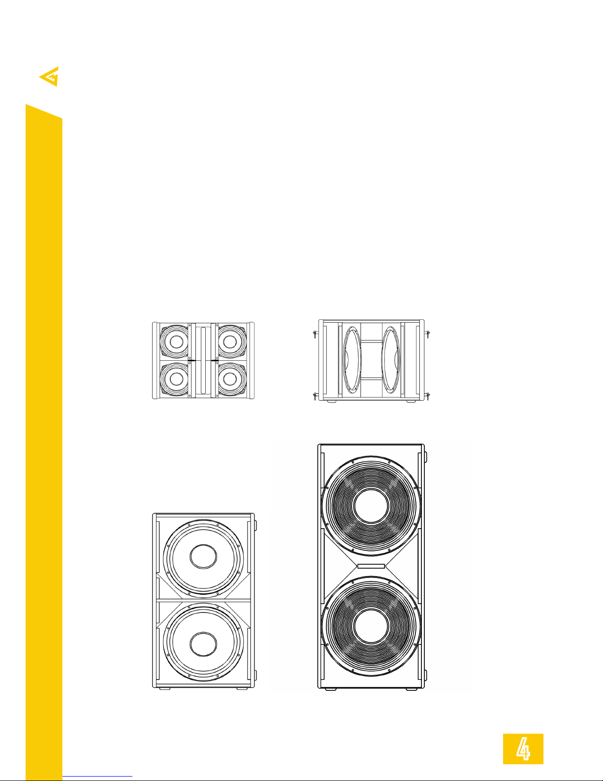
Fly 6 is a line array module with fixed vertical curvature (20°). Closed enclosure with four 6” midrange transducers and two 1,75” VC HF drivers is complete with integrated flying/stacking system
and pole mount adapter.
Fly Sub 12 is a convenient low frequency supplement for Fly 6 system, capable of being flown or
ground stacked.
Fly Sub 15 and Fly Sub 18 are low-end supports for the entire system. They are packed with two
high excursion 15-inch or 18-inch cone drivers and equipped with pole mount adapters for Fly 6.
Fly 6
Part No. 0022800516
Fly Sub 12
Part No. 0022800616
Fly Sub 15
Part No. 0022800716
Fly Sub 18
Part No. 0022800816

5
info@mag-audio.com
Tel./Fax: +38 044 277-47-89 www.mag-audio.com
Fly Array User Manual rev 0.1
3.1. Specifications - Technical data
System Fly 6 Fly Sub 12 Fly Sub 15 Fly Sub 18
Type
Powered fixed array
module
Powered array sub-
woofer
Powered array sub-
woofer
Powered array sub-
woofer
Frequency response
(-10dB)
100 – 19000 Hz 60 – 220 Hz 45 – 200 Hz 27 – 150 Hz
Max SPL (peak) 131,5 dB (calculated) 133 dB (calculated) 136 dB (calculated) 138 dB (calculated)
LF Transducer 4х6” 2x 12” 2x 15” 2x 18”
HF Transducer 2x 1”
-
Nominal coverage HxV 100° x 15°
-
Power 1050 W 1400 W 2000 W 2000 W
Amplifier
Class D Powersoft®,
fan cooling
Class D Powersoft®,
fan cooling
Class D Powersoft®,
fan cooling
Class D Powersoft®,
fan cooling
Max input current 4A 5A 10A 10A
Input sensitivity +4 dBV +4 dBV +4 dBV +4 dBV
Input impedance 10 kOhm (bal.) 10 kOhm (bal.) 10 kOhm (bal.) 10 kOhm (bal.)
Settings 4 switchable presets 4 switchable presets 4 switchable presets 4 switchable presets
Connectors XLR in + XLR out XLR in + XLR out XLR in + XLR out XLR in + XLR out
Dimensions (WxHxD) 496х376х402 mm 496х390х694 mm 506х860х578 mm 506x1146x676 mm
Net weight 24 kg 36 kg 59 kg 79 kg
Shipping weight 27 kg 39 kg 63 kg 84 kg
Mounting
Integrated flying
hardware
Integrated flying
hardware
Two M20 distance
pole adapters, Fly
array U-bracket
adapter
Two M20 distance
pole adapter, Fly
array U-bracket
adapter
Enclosure materials
Plywood; wear-
resistant paint
Plywood; wear-
resistant paint
Plywood; wear-
resistant paint
Plywood; wear-
resistant paint
Grill
Steel grill, polymere
protective net
Steel grill Steel grill Steel grill
Color Black Black Black Black

6
Fly Array User Manual rev 0.1
info@mag-audio.com
Tel./Fax: +38 044 277-47-89 www.mag-audio.com
3.2. Specifications - Dimensions
Fly 6
402mm
[15.81"]
496mm
[19.53"]
376mm
[14.78"]
Fly Sub 12
694mm
[27.32"]
390mm
[15.35"]
496mm
[19.53"]
Fly Sub 15
506mm
[19.92"]
578mm
[22.76"]
860mm
[33.86"]
266mm
[10.45"]
266mm
[10.45"]
M20
M20
Fly Sub 18
676mm
[26.61"]
506mm
[19.92"]
1146mm
[45.12"]
364mm
[14.31"]
M20
364mm
[14.33"]
M20
Fly 6
Fly Sub 15 Fly Sub 18
Fly Sub 12

7
info@mag-audio.com
Tel./Fax: +38 044 277-47-89 www.mag-audio.com
Fly Array User Manual rev 0.1
4.1. System operation - Rigging
Fly Array systems are equipped with integrated rigging system for versatile applications.
Rigging must be performed only by trained personnel following the established safety rules.
MAXIMUM WEIGHT RESTRICTIONS MUST BE FOLLOWED AT ALL TIMES!
MAKE SURE THE SUPPORT STRUCTURE IS CAPABLE OF HOLDING THE APPLIED WEIGHT
WHILE SUSPENDING THE SYSTEM!
Fly 6 system flying via flying adapter
Required accessories:
FL-01 (part No. 0200101101) - 1 pcs
FL-02 (part No. 0200101102) - 1 pcs
VA-0010 (part No. 0209000001) - 2 pcs
- Align FL-02 flying adapter with rests of FL01 bracket.
- Insert two VA-0010 Quick lock pins into the
sockets to fix the assembly.
- Release two locking pins on the Fly 6
integrated hardware.
- Insert the FL-01 + FL-02 assembly to find
supports on the Fly 6 hardware supports.
- Insert two locking pins to secure the
connection.
MAXIMUM OF THREE FLY 6 SYSTEMS ARE
ALLOWED FOR SUSPENSION WITH FL-02
ADAPTER.
Standard 5/8” shackle may be used to
suspend the entire system.
Attaching two Fly 6 systems
- On the upper Fly 6 system release quick lock
pins, pull the integrated link down, and secure
it with the quick lock pin.
- Position the lower Fly 6 cabinet so its
integrated link finds support in the upper
cabinet’s hardware.
- Secure connection with a quick lock pins

8
Fly Array User Manual rev 0.1
info@mag-audio.com
Tel./Fax: +38 044 277-47-89 www.mag-audio.com
4.1. System operation - Rigging
Fly 6 flying angle reference
Flying socket number
1 2 3 4 5 6 7
1 cabinet + 21° + 12,5° + 2,5° - 7,5° - 16° - 24° - 29°
2 cabinets + 20,5° + 14° + 8° + 2° - 4° - 9,5° - 15°
3 cabinets + 24,5° + 19,5° + 14° + 9 ° + 4° - 0,5° - 4,5°
Fly 6 with FL-01 and FL-02
flying socket number reference
“ - “ angle “ + “ angle
Single, two or three Fly 6 cabinets are capable to be flown via FL-01 and FL-02 accessories. Table
above states the angle between horizontal plane and vertical axis of the top-most cabinet. Positive
angle means cabinets are “looking up“, negative angle means cabinets are “looking down“.
1 2 3 4 5 6 7
Attaching two Fly Sub 12s
- On the lower Fly Sub 12 system release
quick lock pins, pull the integrated link up, and
secure it with the quick lock pins.
- Position the lower Fly Sub 12 system so its
integrated link finds support in the upper
cabinet’s hardware.
- Secure connection with a quick lock pins.
Refer to the instruction on the system’s
hardware for more detailed walkthrough
Attaching Fly 6 to Sub 12
- On the lower Fly 6 system release quick lock
pins, pull the integrated link up, and secure it
with the quick lock pins.
- Position the lower Fly 6 system so its
integrated link finds support in the upper
cabinet’s hardware.
- Secure connection with a quick lock pins.
Refer to the instruction on the system’s
hardware for more detailed walkthrough

9
info@mag-audio.com
Tel./Fax: +38 044 277-47-89 www.mag-audio.com
Fly Array User Manual rev 0.1
Fly Sub 12 system flying via flying adapter
Required accessories:
FL-01 (part No. 0200101101) - 2 pcs
FL-04 (part No. 0200101102) - 1 pcs
VA-0010 (part No. 0209000001) - 4 pcs
- Release quick locking pins on the top of the
Fly Sub 12.
- Insert two FL-01 flying brackets into the
supports of the Fly Sub 12 hardware.
- Insert two VA-0010 quick lock pins into the
sockets to fix the assembly.
- Align the FL-04 flying adapter with sockets
of the FL-01 flying brackets.
- Insert four VA-0010 quick lock pins to
secure the connection.
MAXIMUM OF THREE FLY SUB 12 SYSTEMS
ARE ALLOWED FOR SUSPENSION WITH FL04 ADAPTER.
Standard 5/8” shackles may be used to
suspend the entire system.
4.1. System operation - Rigging

10
Fly Array User Manual rev 0.1
info@mag-audio.com
Tel./Fax: +38 044 277-47-89 www.mag-audio.com
Fly array stacked via pole mount adapter
Required accessories:
FL-01 (part No. 0200101101) - 1 pcs
FL-03 (part No. 0200101103) - 1 pcs
SAT-3T (part No. 0209000020) - 1 pcs
VA-0010 (part No. 0209000001) - 2 pcs
- Align FL-03 flying adapter with rests of FL01 bracket.
- Insert two VA-0010 Quick lock pins into the
sockets to fix the assembly.
- Release two locking pins on the Fly 6
integrated hardware.
- Insert the FL-01 + FL-03 assembly to find
supports on the Fly 6 hardware supports.
- Insert two locking pins to secure the
connection.
- Mount securely the SAT-3T distance pole
into the M20 socket of the Fly Sub 15 or Fly
Sub 18 subwoofer.
- Mount the Fly 6 + FL-01 + FL-03 assembly
onto the SAT-3T distance pole.
MAXIMUM OF TWO FLY 6 SYTEMS ARE
ALLOWED FOR POLE MOUNTING.
4.1. System operation - Rigging
Fly array ground stacked
Required accessories:
FL-01 (part No. 0200101101) - 1 pcs
VA-0010 (part No. 0209000001) - 2 pcs
- Align FL-01 flying adapter with rests of Fly
Sub 15 or Fly Sub 18 hardware.
- Insert two VA-0010 Quick lock pins into the
sockets to fix the assembly.
- Release two locking pins on the Fly 6
integrated hardware.
- Insert the Fly 6 into mounted FL-01 flying
adapter until it finds its supports.
- Insert two locking pins to secure the
connection.
MAXIMUM OF TWO FLY 6 SYSTEMS ARE
ALLOWED FOR GROUND STACKING.

11
info@mag-audio.com
Tel./Fax: +38 044 277-47-89 www.mag-audio.com
Fly Array User Manual rev 0.1
4.2. System operation - amplifiers
LIMIT
TEMP
SIGNAL
READY
PRESET1
PRESET2
PRESET3
PRESET4
PRESET
SELECT
LIMIT
TEMP
SIGNAL
READY
PRESET1
PRESET2
PRESET3
PRESET4
PRESET
SELECT
Fly 6 and Fly Sub 12
built-in power amplifier:
Fly Sub 15 and Fly Sub 18
built-in power amplifier:
1
2
3
4
5
6
7
8
9
10
11 12
1
2
3
4
5
7
10
6
8
9
11
12
1. VOLUME KNOB. Used for adjusting the
volume of the system. Remember to turn
the volume dowm before connecting/
disconnecting INPUT or LINK connectors.
2. LIMIT LED. Is lit when limiter is
operational, indicating excessive signal
through the system.
3. TEMP LED. Is lit when tempreture
protection is in place, indicating
overheating.
4. SINGAL LED. Is lit when signal is present
on the INPUT connector.
5. READY LED. Is lit when system is fully
operational.
6. PRESET LEDS. Indicate the currently
selected system preset. For preset
description, refer to the “4.4 System
Operation - Configurations” section of this
manual, page 13.
7. LINK CONNECTOR. Used for linking
additional compactible system to same
signal source.
8. INPUT CONNECTOR. Used for
connecting the system to the signal
source (mixing console etc.)
9. PRESET SELECT BUTTON. Used for
switching currently selected system
preset.
10. HEAT SINK. Large heat sink for
eective heat dissipation.
11. PowerCon A CONNECTOR. Used for
connecting mains supply to the system.
12. PowerCon B CONNECTOR. Used for
feeding the mains supply to the additional
system.

12
Fly Array User Manual rev 0.1
info@mag-audio.com
Tel./Fax: +38 044 277-47-89 www.mag-audio.com
4.3. System operation - Connections and setup
Mains connection. Fly Array systems are supplied with CN-0010 PowerCon-E/F CEE 7/7 mains
cable (part number 0204000003). Use only original or supplied by manufacturer mains cables!.
Fly Array systems are equipped with PowerCon B mains power outlets for mains link to additional
Fly system. For linking several Fly 6 full-range systems CN-0011 PowerCon link cable may be used.
(Part number 0204000004, not supplied with the system).
Fly Array systems nominal mains power specifications: AC 220V, 50/60 Hz.
Nominal voltage tolerance: 100 - 250 V.
To power the system up, connect the mains cable to the system, then to the power outlet.
To completely power down the system, disconnect the mains cable from the power outlet.
Maximum number of Fly Array systems for power linking.
Do not exceed the number of power linked system listed below:
Fly 6 - no more than 5 pcs.
Fly Sub 12 - no more than 4 pcs.
Fly Sub 15 - no more than 2 pcs.
Fly Sub 18 - no more than 2 pcs.
Signal connections. Fly Array systems are equipped with XLR INPUT an XLR LINK connectors for
signal connection.
Use of balanced XLR connector cables is recommended. In case when balanced XLR connections are
not available, unbalanced XLR connection is acceptable.
For linking the additional system to the same signal bus LINK connector may be used.
1
2
3
Shield (Ground)
Plus (+)
Minus (-)
Balanced XLR Plug connections
Unbalanced XLR Plug connections
Fly Array systems connection
Mains power cable
CN-0010
PowerCon - Power-
Con mains link
(optional)
XLR - XLR signal link
(optional)
XLR signal
cable
1
2
3
Shield (Ground)
Plus (+)
Shield (Ground)
Fly 6 Fly 6 Fly 6 Fly 6
Fly 6 Fly 6
Fly Sub 12
Fly Sub 12 Fly Sub 12 Fly Sub 12 Fly Sub 12
Fly Sub 15
Fly Sub 15 Fly Sub 15 Fly Sub 18
Fly Sub 18 Fly Sub 18
Fly Array systems power linking
Mains
Mains
Mains
Mains

13
info@mag-audio.com
Tel./Fax: +38 044 277-47-89 www.mag-audio.com
Fly Array User Manual rev 0.1
4.4. System operation - Configurations
Fly Array systems presets. Fly array system’s amplifiers are storing several presets for dierent
applications.
Fly Array systems presets descriptions:
System Fly 6 Fly Sub 12 Fly Sub 15 Fly Sub 18
PRESET 1
For use of single
cabinet
3-way system, normal
cabinet
3-way system, frontal
cabinet
3-way system, frontal
cabinet
PRESET 2
For two cabinets stack 3-way system, invert-
ed cabinet (cardioid
stack)
3-way system, inverted cabinet (cardioid
stack)
3-way system, inverted cabinet (cardioid
stack)
PRESET 3
For three cabinets
stack
4-way system, normal
cabinet
4-way system, frontal
cabinet
4-way system, frontal
cabinet
PRESET 4
For four cabinets
stack
4-way system, inverted cabinet (cardioid
stack)
4-way system, inverted cabinet (cardioid
stack)
4-way system, inverted cabinet (cardioid
stack)
Fly Array systems are series of versatile speaker suitable for dierent applications and task scopes.
1x Fly 6
Fly 6
PRESET 1
2x Fly 6
Fly 6
PRESET 2
3x Fly 6
Fly 6
PRESET 3
4x Fly 6
Fly 6
PRESET 4
Fly 6
PRESET 2
Fly 6
PRESET 3
Fly 6
PRESET 3
Fly 6
PRESET 4
Fly 6
PRESET 4
Fly 6
PRESET 4
Fly Sub 12, Fly Sub 15 and Fly Sub 18 cardioid usage. Fly Array subwoofer systems are capable to
be united into the cardioid low frequency arrays. For this purpose, the inverted subwoofer system
must be installed backwards, and corresponding preset must be used (PRESET 2 for 3 way system,
PRESET 4 for 4 way system).
Two unit and three unit cardioid subwoofer arrays. Cardioid arrays using two or three Fly Array
subwoofers are available. For dierent number of subwoofers, dierent settings should be used for
best results.
For two unit subwoofer array, put the frontal subwoofer’s Volume Knob in +6dB position, and put
the inverted subwoofer’s Volume Knob in 0dB position
For three unit subwoofer array, put the Volume Knobs of all subwoofers in +6dB position.
Fly 6 configurations. Fly 6 full-range speaker systems should be set up dierently while using
dierent number of units in stack. For this purpose, dierent presets on all speaker in the stack
should be used:
Two unit cardioid array
volume knobs positions
Main
subwoofer
Inverted
subwoofer
Three unit cardioid array
volume knobs positions
Main
subwoofer
Inverted
subwoofer

14
Fly Array User Manual rev 0.1
info@mag-audio.com
Tel./Fax: +38 044 277-47-89 www.mag-audio.com
4.4. System operation - Configurations
Fly Sub 15 and Fly Sub 18 configurations. Fly Sub 15 and Fly Sub 18 are main low-frequency reinforcement
systems for Fly Array. They are capable to be used in 3- or 4-way set, and be assembled into cardioid arrays.
Fly Sub 15 and Fly Sub 18 preset usage refarence:
3-way system
3-way cardioid system
Fly 6
Stack
4-way system
Fly Sub 12
PRESET 3
Fly Sub 12
PRESET 3
Fly 6
Stack
Fly Sub 15
or
Fly Sub 18
PRESET 3
4-way cardioid system
Fly Sub 12
PRESET 3
Fly Sub 12 (inv)
PRESET 4
Fly 6
Stack
Fly Sub 12
PRESET 3
Fly Sub 15
or
Fly Sub 18
PRESET 3
Fly Sub 15 (inv)
or
Fly Sub 18 (inv)
PRESET 4
Fly Sub 15
or
Fly Sub 18
PRESET 3
Fly Sub 15
or
Fly Sub 18
PRESET 1
Fly Sub 15
or
Fly Sub 18
PRESET 1
Fly Sub 15 (inv)
or
Fly Sub 18 (inv)
PRESET 2
Fly Sub 15
or
Fly Sub 18
PRESET 1
Fly 6
Stack
3-way system
Fly Sub 12
PRESET 1
3-way cardioid system
Fly Sub 12
PRESET 1
Fly 6
Stack
Fly Sub 12
PRESET 1
Fly Sub 12
(inv)
PRESET 2
Fly 6
Stack
Fly Sub 12
PRESET 1
4-way system
Fly Sub 12
PRESET 3
Fly Sub 12
PRESET 3
Fly 6
Stack
Fly Sub 15 or
Fly Sub 18
PRESET 3
4-way cardioid system
Fly Sub 12
PRESET 3
Fly Sub 12
(inv)
PRESET 4
Fly 6
Stack
Fly Sub 12
PRESET 3
Fly Sub 15 or
Fly Sub 18
PRESET 3
Fly Sub 15 or
Fly Sub 18 (inv)
PRESET 4
Fly Sub 15 or
Fly Sub 18
PRESET 3
Fly Sub 12 configurations. Fly Sub 12 is low frequency supplement for Fly Array system and is used primarily
for 4-way systems or situations where ground stacked subwoofers are not an option.
Fly Sub 12 preset usage reference:

15
info@mag-audio.com
Tel./Fax: +38 044 277-47-89 www.mag-audio.com
Fly Array User Manual rev 0.1
6. Accessories
Various accessories are available for Fly Array systems:
FL-01 flying bracket
Part No. 0200101101
FL-02 flying adapter
Part No. 0200101102
FL-03 pole
flying adapter
Part No. 0200101103
FL-04 flying adapter
Part No. 0200101800
SAT-3T distance pole
Part No. 0209000020
CN-0010 PowerCon
mains cable
Part No. 0204000003
CN-0011 PowerCon
mains link
Part No. 0204000004
5. Standard contents
Please check complete complement of your Fly Array system upor receiving the package.
Standard contents of Fly Array systems:
System Fly 6 Fly Sub 12 Fly Sub 15 Fly Sub 18
1 pcs - Fly 6 powered fixed array
module
4 pcs - VA-0010
quick lock pin
1 pcs - CN-0010
- PowerCon mains
cable
1 pcs - Fly Array User
Manual
1 pcs - Polyethylene
bag
1 pcs - Carton Box
1 pcs - Fly Sub 12
- powered array
subwoofer
8 pcs - VA-0010
quick lock pin
1 pcs - CN-0010
- PowerCon mains
cable
1 pcs - Fly Array User
Manual
1 pcs - Polyethylene
bag
1 pcs - Carton Box
1 pcs - Fly Sub 15
- powered array
subwoofer
1 pcs - CN-0010
- PowerCon mains
cable
1 pcs - Fly Array User
Manual
1 pcs - Polyethylene
bag
1 pcs - Carton Box
1 pcs - Fly Sub 18
- powered array
subwoofer
1 pcs - CN-0010
- PowerCon mains
cable
1 pcs - Fly Array User
Manual
1 pcs - Polyethylene
bag
1 pcs - Carton Box
Fly6-TB - Fly 6 transportation bag Part No. 0203500090
FlySub12-TB - Fly Sub 12 transportation bag Part No. 0203500001
FlySub15-TB - Fly Sub 15 transportation bag Part No. 0203500002
FlySub18-TB - Fly Sub 18 transportation bag Part No. 0203500003
VA-0010 quick lock pin
Part No. 0209000001

16
Fly Array User Manual rev 0.1
info@mag-audio.com
Tel./Fax: +38 044 277-47-89 www.mag-audio.com
info@mag-audio.com
Tel./Fax: +38 044 277-47-89 www.mag-audio.com
MANUFACTURER’S WARRANTY
1. By this warranty MAG Audio grants that all equipment manufactured under the MAG Audio trademark is
free from defects in material, components and factory workmanship under the normal use and maintenance
for the time as specified below.
2. All warranty repairs and maintenance of MAG Audio products shall be carried out at MAG Audio
production sites or by MAG Audio authorized personnel at no cost for the product purchaser.
3. Warranty period for all the MAG Audio products is 36 months from the date of purchase.
4. Warranty repairs or maintenance will be performed only if a) MAG Audio product was purchased from
an ocial MAG Audio distributor / dealer and b) warranty card with specified serial number, production
date, realization date, vendor’s signature and stamp is presented.
5. Warranty shall not cover following: damage caused by accident, misuse or failure to follow exploitation
rules stated in technical manual; intentional damage; repairs performed by non-authorized personnel;
mechanical damage caused by shipping accidents and normal tear and wear.
6. Warranty shall not be applicable to any product with defaced, removed, or modified serial number.
7. If your MAG Audio product needs repairs or maintenance, contact your ocial MAG Audio distributor
/ dealer. Please do not ship your MAG Audio product without prior authorization.
MANUFACTURER’S CONTACTS
2 Merezhna street, Bila Tserkva, Kiev region, 09112, Ukraine
Tel.\Fax: +38 044 277 47 89
e-mail: info@mag-audio.com
www.mag-audio.com
YOUR MAG AUDIO DISTRIBUTOR / DEALER
Company
Contact
person
Coordinates
 Loading...